
Optical Microscopes - whats a microscope
The calculation above assumes a uniform beam intensity profile. You must now consider hotspots in the beam or other non-uniform intensity profiles and roughly calculate a maximum power density. For reference, a Gaussian beam typically has a maximum power density that is twice that of the uniform beam (see lower right).
Use this formula to calculate the Adjusted LIDT for an optic based on your pulse length. If your maximum energy density is less than this adjusted LIDT maximum energy density, then the optic should be suitable for your application. Keep in mind that this calculation is only used for pulses between 10-9 s and 10-7 s. For pulses between 10-7 s and 10-4 s, the CW LIDT must also be checked before deeming the optic appropriate for your application.
Notchfilter
In order to illustrate the process of determining whether a given laser system will damage an optic, a number of example calculations of laser induced damage threshold are given below. For assistance with performing similar calculations, we provide a spreadsheet calculator that can be downloaded by clicking the button to the right. To use the calculator, enter the specified LIDT value of the optic under consideration and the relevant parameters of your laser system in the green boxes. The spreadsheet will then calculate a linear power density for CW and pulsed systems, as well as an energy density value for pulsed systems. These values are used to calculate adjusted, scaled LIDT values for the optics based on accepted scaling laws. This calculator assumes a Gaussian beam profile, so a correction factor must be introduced for other beam shapes (uniform, etc.). The LIDT scaling laws are determined from empirical relationships; their accuracy is not guaranteed. Remember that absorption by optics or coatings can significantly reduce LIDT in some spectral regions. These LIDT values are not valid for ultrashort pulses less than one nanosecond in duration.
As described above, the maximum energy density of a Gaussian beam is about twice the average energy density. So, the maximum energy density of this beam is ~0.7 J/cm2.
Spherical aberrations are very important in terms of the resolution of the lens because they affect the coincident imaging of points along the optical axis and degrade the performance of the lens, which will seriously affect specimen sharpness and clarity. These lens defects can be reduced by limiting the outer edges of the lens from exposure to light using diaphragms and also by utilizing aspherical lens surfaces within the system. However, a consequence of reducing aperture size in the microscope optical system is a concurrent reduction in the amount of light entering the system. Spherical aberration is usually corrected by employing glass elements (lens doublets or triplets) cemented together. The glass elements are designed with different shapes of convexity and/or concavity to insure that the peripheral rays and axial rays, especially at the outer area of the field of view, are brought into common focus.
The constructive interference conditions of a Fabry-Perot cavity allow light at the center wavelength, and a small band of wavelengths to either side, to be transmitted efficiently, while destructive interference prevents the light outside the passband from being transmitted. However, the band of blocked wavelengths on either side of the center wavelength is small. To increase the blocking range of the filter, materials with broad blocking ranges are used as the substrate or to coat the spacer layers. Although these materials effectively block out-of-band transmission of incident radiation, they also decrease the transmission through the filter in the passband.
Pulsed Nanosecond Laser Example: Scaling for Different Pulse DurationsSuppose that a pulsed Nd:YAG laser system is frequency tripled to produce a 10 Hz output, consisting of 2 ns output pulses at 355 nm, each with 1 J of energy, in a Gaussian beam with a 1.9 cm beam diameter (1/e2). The average energy density of each pulse is found by dividing the pulse energy by the beam area:
Pulsed Nanosecond Laser Example: Scaling for Different WavelengthsSuppose that a pulsed laser system emits 10 ns pulses at 2.5 Hz, each with 100 mJ of energy at 1064 nm in a 16 mm diameter beam (1/e2) that must be attenuated with a neutral density filter. For a Gaussian output, these specifications result in a maximum energy density of 0.1 J/cm2. The damage threshold of an NDUV10A Ø25 mm, OD 1.0, reflective neutral density filter is 0.05 J/cm2 for 10 ns pulses at 355 nm, while the damage threshold of the similar NE10A absorptive filter is 10 J/cm2 for 10 ns pulses at 532 nm. As described on the previous tab, the LIDT value of an optic scales with the square root of the wavelength in the nanosecond pulse regime:
LIDT in linear power density vs. pulse length and spot size. For long pulses to CW, linear power density becomes a constant with spot size. This graph was obtained from [1].
It is also possible for a user to inadvertently introduce spherical aberration into a well-corrected system. For example, when using high magnification, high numerical aperture dry objectives, the correct thickness of the cover glass (suggested to be 0.17 millimeters) is critical. Figure 3 illustrates the changes in half-width of the intensity distribution curve with changes in cover glass thickness. Even with high quality cover glasses having a tolerance of ±10 micrometers, the half-width changes by more than a factor of two. As the objective numerical aperture is increased (above a value of 0.5), particularly with dry and water immersion lenses, selection of cover glasses for the correct thickness is particularly important.
The most serious of the classical Seidel monochromatic lens aberrations that occurs with microscope objectives, spherical aberration, causes the specimen image to appear hazy or blurred and slightly out of focus. Ideally, an aberration-free objective converts a plane wavefront into a spherical wavefront, directing all light waves refracted by the lens to a common focal point in the center of the sphere to produce a perfect image.
Most of the discrepancy in focal points arises from approximations of the equivalency of sine and tangent values of respective angles made to the Gaussian lens equation for a spherical refracting surface:
Please note that we have a buffer built in between the specified damage thresholds online and the tests which we have done, which accommodates variation between batches. Upon request, we can provide individual test information and a testing certificate. Contact Tech Support for more information.
where n and n' represent the refractive index of air and the glass comprising the lens, respectively, s and s' are the object and image distance, and r is the radius of curvature of the lens. This expression determines the relative locations of images formed by the curved surface of a lens having radius r sandwiched between media of refractive indices n and n'. A refinement of this equation is often referred to as a higher-order (first, second, or third) correction by including terms in the cube of the aperture angle, resulting in a more refined calculation. Departure from an ideal spherical wave is expressed in terms of fractions of a wave, where a single wave is equal to the average wavelength of the illuminating light. This deviation is termed the optical path difference, which must be less than one-quarter wavelength before a diffraction limited objective can be considered aberration-free.
Thorlabs is investing in green initiatives to replace plastic and foam optics packaging with more sustainable solutions. Leave feedback or learn more about what went into the design of our pilot program for Ø1" single optics here.
Spherical aberration artifacts are encountered when light waves passing through the periphery of an uncorrected convex lens are not brought into focus with those passing through the center. Waves passing near the center of the lens are refracted only slightly, whereas waves passing near the periphery are refracted to a greater degree, producing a variety of different focal points along the optical axis. As a result, the peripheral waves come to a shorter focus (nearer the back of the lens or objective) than do rays traveling through the central or axial area. This is known as longitudinal or axial spherical aberration. Axial aberration is generated by non-spherical wavefronts produced by the objective itself or by improper use of the objective. Some of the most common causes are failure to maintain the designated microscope tube length or the presence of substances between the objective and focal plane having a spurious refractive index.
Soft-coated and hard-coated filters are commonly sold in the optics industry. Soft-coated filters suffer from poor temperature stability, low transmission, high optical scatter, and a short shelf life owing to their laminate structure of chemically reactive layers. The hard-coated filters do not suffer from these shortcomings as they are formed of chemically inert layers on an optical substrate via a high-energy sputtering technique.
The energy density of the beam can be compared to the LIDT values of 1 J/cm2 and 3.5 J/cm2 for a BB1-E01 broadband dielectric mirror and an NB1-K08 Nd:YAG laser line mirror, respectively. Both of these LIDT values, while measured at 355 nm, were determined with a 10 ns pulsed laser at 10 Hz. Therefore, an adjustment must be applied for the shorter pulse duration of the system under consideration. As described on the previous tab, LIDT values in the nanosecond pulse regime scale with the square root of the laser pulse duration:
The center wavelength of the filter can be tuned slightly (~1 nm over the operating range of the filter) by changing the temperature of the filter. This is primarily due to the slight thermal expansion or contraction of the layers.
The pulse length must now be compensated for. The longer the pulse duration, the more energy the optic can handle. For pulse widths between 1 - 100 ns, an approximation is as follows:
MATLABbandpass
What is seen in the microscope is an image made by focusing the peripheral rays surrounded by the unfocused image of rays traveling through the central portion of the lens (or visa versa). This is one of the most serious resolution artifacts because the image of the specimen is spread out rather than being in sharp focus. The best focus, in an imperfectly or non-corrected lens, will be somewhere between the focal planes of the peripheral and axial rays, an area known as the disc of least confusion (illustrated as a point on the optical axis in the tutorial figure). Light rays refracted by the rim of the lens or pupil (peripheral rays) have the shortest focal length and produce the smallest image, whereas those that intersect at the paraxial focal point (axial rays) have begun to spread and do not represent the "best" focus.
Opticalfilter
This adjustment factor results in LIDT values of 0.45 J/cm2 for the BB1-E01 broadband mirror and 1.6 J/cm2 for the Nd:YAG laser line mirror, which are to be compared with the 0.7 J/cm2 maximum energy density of the beam. While the broadband mirror would likely be damaged by the laser, the more specialized laser line mirror is appropriate for use with this system.
Beam diameter is also important to know when comparing damage thresholds. While the LIDT, when expressed in units of J/cm², scales independently of spot size; large beam sizes are more likely to illuminate a larger number of defects which can lead to greater variances in the LIDT [4]. For data presented here, a <1 mm beam size was used to measure the LIDT. For beams sizes greater than 5 mm, the LIDT (J/cm2) will not scale independently of beam diameter due to the larger size beam exposing more defects.
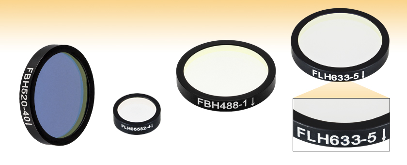
Each filter is housed in a black anodized aluminum ring that is labeled with an arrow indicating the design propagation direction. The ring makes handling easier and enhances the blocking OD by limiting scattering. These filters can be mounted in our extensive line of filter mounts and wheels. As the mounts are not threaded, retaining rings will be required to mount the filters in one of our internally threaded lens tubes. We do not recommend removing the filter from its mount as the risk of damaging the filter is very high.
Specimens mounted in Canada balsam or similar mounting media that have a refractive index approximating that of the cover glass are not prone to spherical aberration errors. However, this is not true for specimens mounted in physiological saline or other aqueous media with refractive indices significantly different from the cover glass. Even when focusing through thin layers of water only a few microns thick, significant aberrations are encountered that can induce dramatic asymmetries into the point spread function causing a non-uniform distribution above and below the focal plane. This concept is explored in the interactive tutorial linked below.
These bandpass filters feature durable, hard-coated dielectric coatings on a UV fused silica substrate. The film construction is essentially a modified quarter-wave stack, using interference effects to isolate spectral bands. The dense coating on these filters allows them to be constructed using a single substrate, which yields a stable, long-lasting filter. This coating can withstand the normal cleaning and handling necessary when using any high-quality optical component. Please see the Comparison tab for information about the advantages of hard-coated filters compared to soft-coated filters, such as increased durability and transmission performance.
Only when the specimen and image distances can be accurately specified can spherical aberration be optimally corrected. This artifact can be easily introduced by improper tube length caused by introduction of optical elements into the converging beam path of finite tube length microscopes. Spherical aberration can also occur when using improper "windows", such as cover glasses of nonstandard thickness (deviations from 0.17 millimeters) or poor quality immersion oil between the objective front lens and the cover glass.
Low passfilter
The tutorial initializes with an image of the specimen (as seen through the microscope) appearing in a window on the left-hand side of the applet. Beneath the image window is a pull-down menu labeled Choose A Specimen, used to select a new specimen. The Lens Shape slider is designed to control the tutorial by introducing an increasing amount of spherical aberration into the optical system. Moving the slider to the right also induces changes corresponding to the introduction of spherical aberration into the Airy diffraction pattern shown in the center of the applet window. Simultaneously, intensity is shifted away from the central peak of the point spread function and into the surrounding rings, which become far more prominent. These changes are also correlated with the ray trace diagram presented in the right-hand side of the applet.
Pulsed Microsecond Laser ExampleConsider a laser system that produces 1 µs pulses, each containing 150 µJ of energy at a repetition rate of 50 kHz, resulting in a relatively high duty cycle of 5%. This system falls somewhere between the regimes of CW and pulsed laser induced damage, and could potentially damage an optic by mechanisms associated with either regime. As a result, both CW and pulsed LIDT values must be compared to the properties of the laser system to ensure safe operation.
Until recent years, achromats were corrected spherically only for green light, although they were corrected chromatically for two wavelengths. Also, apochromats were corrected spherically for two wavelengths, blue and green, but were corrected chromatically for three wavelengths. The highest-quality modern microscope objectives address spherical aberrations in a number of ways including special lens-grinding techniques, improved glass formulations, and better control of optical pathways through use of multiple-lens elements. Currently, the highest quality objectives, planapochromats, are spherically corrected for four wavelengths, as are planfluorites (but not to quite as close a tolerance).
The energy density of your beam should be calculated in terms of J/cm2. The graph to the right shows why expressing the LIDT as an energy density provides the best metric for short pulse sources. In this regime, the LIDT given as an energy density can be applied to any beam diameter; one does not need to compute an adjusted LIDT to adjust for changes in spot size. This calculation assumes a uniform beam intensity profile. You must now adjust this energy density to account for hotspots or other nonuniform intensity profiles and roughly calculate a maximum energy density. For reference a Gaussian beam typically has a maximum energy density that is twice that of the 1/e2 beam.
Thorlabs' hard-coated bandpass filters, which are designed to provide enhanced isolation of key Yb:YAG, Nd:YAG, HeNe, Ar, and diode laser lines, offer excellent (ODavg ≥ 4) suppression in the blocking region while providing ≥85% transmission at the design wavelength (except the 300 nm filter which offers ≥50% transmission). They are available with 12.5 mm or 25 mm outer diameters and are 3.5 mm thick, which allows the Ø25 mm filters to be used as drop-in replacements for our fluorescence emission filters.
If this relatively long-pulse laser emits a Gaussian 12.7 mm diameter beam (1/e2) at 980 nm, then the resulting output has a linear power density of 5.9 W/cm and an energy density of 1.2 x 10⁻⁴ J/cm2 per pulse. This can be compared to the LIDT values for a WPQ10E-980 polymer zero-order quarter-wave plate, which are 5 W/cm for CW radiation at 810 nm and 5 J/cm2 for a 10 ns pulse at 810 nm. As before, the CW LIDT of the optic scales linearly with the laser wavelength, resulting in an adjusted CW value of 6 W/cm at 980 nm. On the other hand, the pulsed LIDT scales with the square root of the laser wavelength and the square root of the pulse duration, resulting in an adjusted value of 55 J/cm2 for a 1 µs pulse at 980 nm. The pulsed LIDT of the optic is significantly greater than the energy density of the laser pulse, so individual pulses will not damage the wave plate. However, the large average linear power density of the laser system may cause thermal damage to the optic, much like a high-power CW beam.
bandpassfilter中文
Thorlabs' Visible Bandpass Filter Kits each contain 10 mounted hard-coated bandpass filters that can be used to transmit a well-defined wavelength band in the visible, while rejecting other unwanted radiation. Each filter is mounted in an unthreaded Ø25.0 mm black-anodized aluminum ring that can be placed into our selection of Ø1" lens tubes and filter mounts using retaining rings. The filter kits come in a convenient plastic box for storage and transportation purposes.
According to the test, the damage threshold of the mirror was 2.00 J/cm2 (532 nm, 10 ns pulse, 10 Hz, Ø0.803 mm). Please keep in mind that these tests are performed on clean optics, as dirt and contamination can significantly lower the damage threshold of a component. While the test results are only representative of one coating run, Thorlabs specifies damage threshold values that account for coating variances.
John C. Long and Michael W. Davidson - National High Magnetic Field Laboratory, 1800 East Paul Dirac Dr., The Florida State University, Tallahassee, Florida, 32310.
Thorlabs expresses LIDT for CW lasers as a linear power density measured in W/cm. In this regime, the LIDT given as a linear power density can be applied to any beam diameter; one does not need to compute an adjusted LIDT to adjust for changes in spot size, as demonstrated by the graph to the right. Average linear power density can be calculated using the equation below.
CW Laser ExampleSuppose that a CW laser system at 1319 nm produces a 0.5 W Gaussian beam that has a 1/e2 diameter of 10 mm. A naive calculation of the average linear power density of this beam would yield a value of 0.5 W/cm, given by the total power divided by the beam diameter:
Hard-coated filters are produced by sputtering dielectric layers onto a glass substrate; the dielectric filter stack can be exposed to the environment, as shown below to the right, without degradation of performance owing to the material being more environmentally stable than what is used for the soft-coated filters. The hard-coated filters are thinner than soft-coated filters, which allows them to be more easily incorporated into space-limited applications. The sputtering process is automated, highly repeatable, and results in a transmitted wavefront error value that is close to that of the uncoated optic.
LIDT in energy density vs. pulse length and spot size. For short pulses, energy density becomes a constant with spot size. This graph was obtained from [1].
The transmission and optical density properties of the hard-coated bandpass filters will vary for far out-of-band wavelengths. The plots below show the variation in transmission and optical density for wavelengths far outside the specified blocking regions of 200 - 379 nm and 401 - 1200 nm for an FBH390-10 hard-coated bandpass filter. The FBH390-10 has a design CWL of 390 nm and a passband FWHM of 10 nm. The blocking region is specified to be ODabs > 5 between the ranges of 200 - 379 nm and 401 - 1200 nm.
bandpass中文
As previously stated, pulsed lasers typically induce a different type of damage to the optic than CW lasers. Pulsed lasers often do not heat the optic enough to damage it; instead, pulsed lasers produce strong electric fields capable of inducing dielectric breakdown in the material. Unfortunately, it can be very difficult to compare the LIDT specification of an optic to your laser. There are multiple regimes in which a pulsed laser can damage an optic and this is based on the laser's pulse length. The highlighted columns in the table below outline the relevant pulse lengths for our specified LIDT values.
The plots below show how the properties of the FLH532-1, FLH1064-3, and FLH1030-10 hard-coated bandpass filters change as the AOI is varied.
A bandpass filter is created by depositing layers of material on the surface of the substrate. For our hard-coated bandpass filters, the coating is comprised of dielectric stacks alternating with dielectric spacer layers. Each dielectric stack is composed of a large number of alternating layers of low-index and high-index material. The thickness of each layer in the dielectric stack is λ/4, where λ is the design center wavelength of the bandpass filter (i.e. the wavelength designed to have highest transmittance through the filter at normal incidence). The spacer layers are placed in between the stacks and have a thickness of (nλ)/2, where n is an integer. A Fabry-Perot cavity is formed by each spacer layer sandwiched between dielectric stacks. The filter is mounted in an engraved metal ring for protection and ease of handling.
As the objective numerical aperture is increased, changes in cover glass thickness or refractive index become critical, particularly with high magnification dry objectives where small changes in tube length quickly lead to inferior images. Although spherical aberration can be corrected to almost undetectable limits for visual observation with all types of objectives, the optical specification for any given lens must be fulfilled. For oil-immersion objectives having high numerical apertures, this usually means using a cover glass having a 0.17 millimeter thickness and immersion oil with a refractive index of 1.5180 (± 0.0004) at wavelengths of 546 and 589 nanometers. Complicating these conditions is the fact that for almost all materials, refractive index is a function of both wavelength and temperature. In cases where the exact properties of the cover glass and oil are specified, microscope manufacturers can correct spherical aberration for several values of wavelength.
Butterworthfilter
The passbands of these filters range from 1 to 40 nm FWHM, depending on the center wavelength chosen, with steep cut-on and cut-off slopes. The center wavelength and passbands for these filters are specified for light normally incident on the surface. For angles of incidence (AOIs) greater than 0°, the band will shift toward a lower center wavelength and the shape of the passband will change. Filters with passbands that have full width half maxima (FWHM) in the 1 to 5 nm range are particularly susceptible to these shifts. For more information, see the Tutorial tab.
The effect of spherical aberration manifests itself in two ways: the center of the image remains more in focus than the edges, and the intensity of the edges falls relative to that of the center. This defect appears in both on-axis and off-axis image points.
Now compare the maximum power density to that which is specified as the LIDT for the optic. If the optic was tested at a wavelength other than your operating wavelength, the damage threshold must be scaled appropriately. A good rule of thumb is that the damage threshold has a linear relationship with wavelength such that as you move to shorter wavelengths, the damage threshold decreases (i.e., a LIDT of 10 W/cm at 1310 nm scales to 5 W/cm at 655 nm):
When an optic is damaged by a continuous wave (CW) laser, it is usually due to the melting of the surface as a result of absorbing the laser's energy or damage to the optical coating (antireflection) [1]. Pulsed lasers with pulse lengths longer than 1 µs can be treated as CW lasers for LIDT discussions.
The performance of soft-coated filters is limited in the visible wavelengths to approximately 80% transmission if silver is not used and approximately 50% transmission if silver is used in the dielectric stack; the transmission is further limited in the UV. As can be seen in the graphs below, the hard-coated filters have improved transmission in the UV and visible wavelength regimes. The cut-on and cut-off for hard-coated filters is relatively steep compared to the soft-coated filters. The transmission is also much flatter for the hard-coated filters compared with the soft-coated, which is due to the sputtering process used that allows more complicated cavity filter designs to be deposited with high precision and repeatability.
Pulses shorter than 10-9 s cannot be compared to our specified LIDT values with much reliability. In this ultra-short-pulse regime various mechanics, such as multiphoton-avalanche ionization, take over as the predominate damage mechanism [2]. In contrast, pulses between 10-7 s and 10-4 s may cause damage to an optic either because of dielectric breakdown or thermal effects. This means that both CW and pulsed damage thresholds must be compared to the laser beam to determine whether the optic is suitable for your application.
The laminated structure of the soft-coated filters means that changes in temperature can have a drastic effect on the optical performance of the filter. The dielectric stack, epoxy, optical substrate, absorption glass, and housing may all have different coefficients of thermal expansion. This may result in the shape of the filter changing in unexpected ways with changes in temperature.
Thorlabs' hard-coated bandpass filters reflect out-of-band light with high efficiency. The plot below shows the measured reflectance of an FBH1200-10 hard-coated bandpass filter with a design CWL of 1200 nm and passband FWHM of 10 nm. The blocking region for this filter is specified as ODabs > 5 between the ranges of 200 - 1180 nm and 1220 - 1700 nm.
Thorlabs' LIDT testing is done in compliance with ISO/DIS 11254 and ISO 21254 specifications.First, a low-power/energy beam is directed to the optic under test. The optic is exposed in 10 locations to this laser beam for 30 seconds (CW) or for a number of pulses (pulse repetition frequency specified). After exposure, the optic is examined by a microscope (~100X magnification) for any visible damage. The number of locations that are damaged at a particular power/energy level is recorded. Next, the power/energy is either increased or decreased and the optic is exposed at 10 new locations. This process is repeated until damage is observed. The damage threshold is then assigned to be the highest power/energy that the optic can withstand without causing damage. A histogram such as that below represents the testing of one BB1-E02 mirror.
The adjusted LIDT value of 350 W/cm x (1319 nm / 1550 nm) = 298 W/cm is significantly higher than the calculated maximum linear power density of the laser system, so it would be safe to use this doublet lens for this application.
An AC127-030-C achromatic doublet lens has a specified CW LIDT of 350 W/cm, as tested at 1550 nm. CW damage threshold values typically scale directly with the wavelength of the laser source, so this yields an adjusted LIDT value:
Please note that we have a buffer built in between the specified damage thresholds online and the tests which we have done, which accommodates variation between batches. Upon request, we can provide individual test information and a testing certificate. The damage analysis will be carried out on a similar optic (customer's optic will not be damaged). Testing may result in additional costs or lead times. Contact Tech Support for more information.
This scaling gives adjusted LIDT values of 0.08 J/cm2 for the reflective filter and 14 J/cm2 for the absorptive filter. In this case, the absorptive filter is the best choice in order to avoid optical damage.
Soft-coated filters are comprised of dielectric layers sandwiched between optical substrates in a housing as shown in the image to the right. The dielectric layers are often composed of fragile materials such as zinc sulfide, cryolite, or silver. These chemicals react with water, which degrades the performance of the filter, so the shelf life of soft-coated filters is greatly reduced in humid environments. The assembly seals will eventually fail due to the environment, handling, and the construction quality of the filter; the optical performance will rapidly degrade once the seals have failed. Soft-coated filters have a typical lifetime of one to five years in a lab environment owing to these factors.
However, the maximum power density of a Gaussian beam is about twice the maximum power density of a uniform beam, as shown in the graph to the right. Therefore, a more accurate determination of the maximum linear power density of the system is 1 W/cm.
When pulse lengths are between 1 ns and 1 µs, laser-induced damage can occur either because of absorption or a dielectric breakdown (therefore, a user must check both CW and pulsed LIDT). Absorption is either due to an intrinsic property of the optic or due to surface irregularities; thus LIDT values are only valid for optics meeting or exceeding the surface quality specifications given by a manufacturer. While many optics can handle high power CW lasers, cemented (e.g., achromatic doublets) or highly absorptive (e.g., ND filters) optics tend to have lower CW damage thresholds. These lower thresholds are due to absorption or scattering in the cement or metal coating.
Pulsed lasers with high pulse repetition frequencies (PRF) may behave similarly to CW beams. Unfortunately, this is highly dependent on factors such as absorption and thermal diffusivity, so there is no reliable method for determining when a high PRF laser will damage an optic due to thermal effects. For beams with a high PRF both the average and peak powers must be compared to the equivalent CW power. Additionally, for highly transparent materials, there is little to no drop in the LIDT with increasing PRF.
An engraved arrow on the edge of the filter is used to indicate the recommended direction for the transmission of light through the filter. Orienting the coated side toward the source will reduce unwanted scattering and minimize reflections sent back toward the source. Using the filter in the opposite orientation will not, however, significantly affect the performance of the filter. The plot to the right was made by illuminating the filter with a low intensity broadband light and measuring the transmission as a function of wavelength. This plot shows that the direction of transmission through the filter has very little effect on the intensity and the spectrum of the light transmitted through the filter. The minimal variation between the forward and backward traces is most likely due to a small shift in the incident angle of the light on the filter introduced when the filter was removed, flipped over, and replaced in the jig.
One of the mechanisms used to eliminate spherical aberration in oil immersion objectives is to design the optics around specific pairs of conjugate points using a hemispherical and meniscus lens at the front of the objective. As illustrated in Figure 2, for a specimen observed at position P and surrounded by immersion oil of refractive index n, there exists a conjugate point (P(1)) to eliminate spherical aberration in the first lens element (the hemispherical lens). In this case, light rays emanating from point P leave the surface of the hemispherical front lens as if they originated at point P(1). The meniscus lens is ground with a surface radius centered on point P to form a second conjugate pair (P(1) and P(2)). Thus, light from the specimen a point P ultimately exits the meniscus lens as if it originated at point P(2), eliminating spherical aberration for the lens combination.
Chebyshevfilter
The tutorial illustrates an exaggerated view of three hypothetical monochromatic light rays passing through a convex lens and converging on a series of focal points that lie in a progression along the optical axis (see the Ray Trace Diagram). Changes to the shape of the lens with corresponding adjustments to the focal point position(s) can be made by utilizing the Lens Shape slider. Refraction of peripheral rays at the edge of the lens is greatest followed by those in the middle and then the rays in the center. The larger refraction by the outermost rays results in a focal point (focal point 1; see Figure 1) that occurs in front of the disc of least confusion and the focal points produced by rays passing closer to the center of the lens (focal points 2 in the center and 3, at the paraxial focal plane; Figure 1). Also illustrated in Figure 1 is a measure of the transverse spherical aberration, defined as the distance from the optical axis at which the peripheral rays intersect the plane of paraxial focus. As is evident in the figure, transverse aberration is measured in the plane of the image and is useful as an indicator of image blur.
Now compare the maximum energy density to that which is specified as the LIDT for the optic. If the optic was tested at a wavelength other than your operating wavelength, the damage threshold must be scaled appropriately [3]. A good rule of thumb is that the damage threshold has an inverse square root relationship with wavelength such that as you move to shorter wavelengths, the damage threshold decreases (i.e., a LIDT of 1 J/cm2 at 1064 nm scales to 0.7 J/cm2 at 532 nm):
The following is a general overview of how laser induced damage thresholds are measured and how the values may be utilized in determining the appropriateness of an optic for a given application. When choosing optics, it is important to understand the Laser Induced Damage Threshold (LIDT) of the optics being used. The LIDT for an optic greatly depends on the type of laser you are using. Continuous wave (CW) lasers typically cause damage from thermal effects (absorption either in the coating or in the substrate). Pulsed lasers, on the other hand, often strip electrons from the lattice structure of an optic before causing thermal damage. Note that the guideline presented here assumes room temperature operation and optics in new condition (i.e., within scratch-dig spec, surface free of contamination, etc.). Because dust or other particles on the surface of an optic can cause damage at lower thresholds, we recommend keeping surfaces clean and free of debris. For more information on cleaning optics, please see our Optics Cleaning tutorial.
While this rule of thumb provides a general trend, it is not a quantitative analysis of LIDT vs wavelength. In CW applications, for instance, damage scales more strongly with absorption in the coating and substrate, which does not necessarily scale well with wavelength. While the above procedure provides a good rule of thumb for LIDT values, please contact Tech Support if your wavelength is different from the specified LIDT wavelength. If your power density is less than the adjusted LIDT of the optic, then the optic should work for your application.
[1] R. M. Wood, Optics and Laser Tech. 29, 517 (1998).[2] Roger M. Wood, Laser-Induced Damage of Optical Materials (Institute of Physics Publishing, Philadelphia, PA, 2003).[3] C. W. Carr et al., Phys. Rev. Lett. 91, 127402 (2003).[4] N. Bloembergen, Appl. Opt. 12, 661 (1973).
The filter is intended to be used with collimated light normally incident on the surface of the filter. For uncollimated light or light striking the surface at an angle not normally incident to the surface, the center wavelength (wavelength corresponding to peak transmission) will shift toward lower wavelengths and the shape of the transmission region (passband) will change. Varying the angle of incidence (AOI) by a small amount can be used to effectively tune the passband over a narrow range. Large changes in the incident angle will cause larger shifts in the center wavelength but will also significantly distort the shape of the passband and, more importantly, cause a significant decrease in the transmittance of the passband. The plots below show examples of the change of the passband, transmission, and center wavelength (CWL) with when the AOI is changed for various filters. Filters with passband full width half maxima (FWHM) in the range of 1 nm to 5 nm are particularly susceptible to these shifts and extra care should be taken to ensure they are set to the desired AOI. The plots below given in order of increasing nominal passband FWHM.
High-quality oil immersion objectives perform optimally only when they are used with a cover glass thickness of 0.17 millimeters. To help alleviate cover glass variations, correction collars are often included on dry objectives to enable adjustment of intermediate lens elements to compensate for deviant cover glass thickness. Because focus may shift and the image may wonder during adjustment of the correction collar, the utilization of correction collars demands that the microscopist remain alert in order to reset the collar using appropriate image criteria. In addition, the insertion of accessories in the light path of finite tube length objectives may introduce aberrations, when the specimen is refocused, unless these accessories have been properly designed with additional optics.


 Ms.Cici
 8618319014500