
ZEISS Microscopy Online Campus | Objectives - objective lens function on a microscope
It’s a little odd that they really haven’t quantified what they mean by ‘straight’. Also, I’m used to seeing flatness on a per unit basis as a refinement of a larger flatness tolerance to prevent abrupt changes in the profile of the part. Not saying what you have is wrong, just a little different.
You should note that if the independency symbol (I) is applied then it is no longer required for your flatness tolerance to be smaller than you size tolerance.
It seems that my mistake comes from the fact that I learnt the ISO standard at school instead of the ASME one. In the ISO standard, the envelope principle must be indicated with a circled “E” when used (source: google book preview of a manual written by Colin H. Simmons & Dennis E. Maguire).
5 things that absorblight
You’ve hit upon one of the few ways that the Rule #1 (perfect form at MMC) can be overruled. As to whether or not you need it, I can’t answer as I’m not intimately familiar with your particular design.
CZ is the common zone modifier where the entire feature that is broken up is to be treated as one surface (this is only the ISO standard.) For the first one, you would only measure the flatness of the individual feature that the control frame is on. For the second you need to surface map all of the common zone features and determine if the flatness of that (acting as one feature) is within the tolerance zone.
How do you decide how flat a surface should be? Are there any prescribed flatness tolerances for sealing faces, tooling, etc? If so, and regarding GD&T more generally where would one find examples of values to adhere to with regards to GD&T?
When you want to constrain the amount of waviness or variation in a surface without tightening the dimensional tolerance of said surface. Usually, flatness is used to give a surface an even amount of wear or for sealing properly with a mating part. Commonly used on a fixture that must mate flush with another part without wobbling, but where orientation is not important.
I’m not entirely sure I get what you’re referring to. However, if you apply the flatness control to a Feature of Size like a tab or a slot you are then controlling the derived median plane’s flatness. The concept is essentially the same as applying straightness to a diametral Feature of Size.
Dear sir, I have drg. of Plate Al. 8 mm thick width 200 mm & length 450 mm. Specified flatness is ±0.02 mm. is it flatness possible within ±0.02 in 450 mm length in machining? present we get flatness within 0.2 mm. kindly suggest. with Regards, Chandrashekhar Joshi.
Materials that absorblightwithout reflecting it back
Flatness can be applied to an entire feature ( in the case of a sheet metal plate) or to just the surface of a part. When applied to a surface of a part the flatness must always be less than the dimensional tolerance. When applied to a feature of size however, it can actually be larger. This is because rule #1 does not apply to flatness and straightness when applied to an entire feature. Thanks for pointing this out!
I would like to add flatness tolerance on a sheet metal part 1.6mm thick. Please can you let me know what is the least tolerance I can apply?
No, a flatness control applies to the entire surface indicated simultaneously. You can apply form controls like straightness, flatness etc. on a per unit basis to limit abrupt changes along a surface or over a specified area. I don’t think that’s what you’re driving at though.
One thing we are looking to add to the site soon is the Rule #1 of GD&T definition also known as the envelope principle. This overarching rule of GD&T states that your form of your part must be controlled by your size. This means your form can never allow your part to go over its size dimension (without certain exceptions) You part must always fit within the envelope that the max (or min) size dimensions create. This means in the table example, if the size of the height was at the max your form would need to be near perfect.
Sorry for the late reply on this. I hate to give you advice and have it be wrong. I really think you should ask the customer for a clearer explanation. You are absolutely correct in that flatness is a tolerance zone described by two parallel planes for a surface and not a +/- value.
My customer has a drawing of part that has a 58′ angle call out and then a flatness call out. Is it possible that both of these features call out at the same time? If it is, should the part layout flat to check or tile the part at 58′ angle to check the flatness?
How much bow is allowed? That all falls back to Rule 1 and perfect form at MMC. Flatness is indirectly controlled by your limits of size and your form error allowed is only equal to the amount of departure from MMC. This is why your flatness tolerance must be a refinement of the size tolerance. To have a part with an intentional bow would be an improper use of the flatness symbol.
I’m afraid I can’t fully answer your question. I’m not aware of your manufacturing capability or your specific design requirements. I do have a question regarding the drawing though. You say the specified flatness is +/-0.02. Flatness, per the ASME standard, is specified as a total value, not as a +/-. Is it possible that the +/-0.02 is a thickness tolerance? If you really are trying to achieve a flatness of 0.04 or 0.02 I would think it’s more than possible, it’s just a matter of finding the right machine shop and processes.
Read this to mean that a flatness error of 0.2 is permitted every 100. This method is often used to prevent abrupt changes in flatness, straightness per unit length or area. For flatness, based on the standard and my experience, the control should read as 0.2 / 10 x 10. Something that indicates that the value following the / indicates an area. Is it possible there is a note or other such callout nearby the control in question? I’ll refer you to Section 5.4.2.2 of the ASME Y14.5 – 2009 standard.
Bestlight absorbing fabric
If you have access to the ASME Y14.5 – 2009 standard I suggest you take a look at Figure 2-7 and Section 2.7.1. It describes your situation perfectly.
So how do I make sense of a flatness of 0.005″ per inch? I’m not thinking this would mean a flatness of 0.060″ for a 1 foot part??
“Must be less” is always true based on ANSI-Y14.5. In fact it is recommended to be half of the tolerance of size. Does not only apply to position.
It can be, however I urge ‘extreme’ caution in doing so. If you call out flatness for multiple surfaces your are only controlling the flatness of each surface to itself (i.e. you aren’t controlling the coplanarity of the surfaces to one another). In the example you give, I could machine the legs of the table to within .00001″ and still have a wobble that would topple the tower in Pisa that no amount of napkins shoved under a leg would cure.
Which materials absorb the mostlight
For me the sentence “Flatness tolerance is always less than the dimensional tolerance associated with it” is only true when the associated dimensional tolerance is a True Position (True Position includes Parallelism which includes Flatness). When the dimension is defined by a +/- as on the diagrams, it means that every local dimension must be compliant, but it gives no indication on the shape on the surface. So you can have a bad Flatness while be compliant with a good dimension (example of a twisted metal plate – the thickness is steady but it can be unflat as rectified when assembled).
GD&T Flatness is very straight forward. It is a common symbol that references how flat a surface is regardless of any other datums or features. It comes in useful if a feature is to be defined on a drawing that needs to be uniformly flat without tightening any other dimensions on the drawing. The flatness tolerance references two parallel planes (parallel to the surface that it is called out on) that define a zone where the entire reference surface must lie. Flatness tolerance is always less than the dimensional tolerance associated with it.
What if the flatness feature control frame id applied to a section running through a surface. Does it control the whole surface?
The problem is severalfold. The first issue is that flatness is only measured against itself, there is no datum reference plane. The second issue is that how can you be absolutely sure (short of a 3D laser scan) that you have actually found the highest point as you reference. The three point (column) method serves to establish a starting point and not really a datum reference. Recall that 3 points define a plane that should in reality be a pretty good representation of the surface you are checking. Then you can take your indicator probe and sweep the surface with flatness.
The geometric tolerance all depends on what is functionally required. For certain application such as a bracket, a higher flatness would be fine. But for a more precise application such as a sealing surface you may need a tighter tolerance.
I was really glad to find such a quality website for GD&T because the descriptions are quite clear (especially for the Runout which is, to me, too often badly understood), but I will need to verify the conformity of what I learnt to the ISO standard.
in the above table example i can’t understand the differentiation between a tight tolerance zone and a flatness calledout one(ie without gdt and with gdt), so can you please make it more understandiable for me.
A surface is datum A and has a flatness callout of .003. A CMM take a bunch of points on that surface and it says that the flatness is .008.
It’s possible that I’m wrong but I think you’re measuring a flatness error of .01 despite your rationalization to the contrary. If you’re interested there are independent inspection shops out there that could verify your part for you in short order.
what is different in the following flatness specification of a wheel and how to measure the latter one? 1. φ27mm,φ40mm 0.1 2. φ27mm,φ40mm 0.1CZ
There is no rule preventing a datum from having a profile tolerance it really depends on how you have things set up. Keep in mind the datums indicate how the part is to be set up for inspection. As is your case you would have a mutually orthogonal DRF, so your set up would have the broad flat surface contact the inspection equipment first, then the secondary datum and lastly the tertiary. From this intersection of three planes you would base all of your measurements from. Adding a profile tolerance would have the effect of ‘shifting’ the pattern one way or another as compared to the overall length and width of the part. This is because your pattern still has to be basically located to the datums. You would essentially be adding material to the far side of the part.
Regarding your jacks, the general statement is to have them spaced as far apart as practical for stability and quality measurement.
So flatness is a little bit odd. You aren’t comparing the surface to anything but itself. The easiest way to inspect the flatness would be with a CMM, but since your asking I’m assuming that you don’t have one. There are a couple of old school methods for doing this inspection. Probably the easiest one would be to have a suitable inspection surface with a hole in it large enough for the probe of a dial indicator. Place your part on the inspection surface over the dial indicator and set the bezel to 0. Then move the part 1 mm while keeping an eye on the indicator. If at any point your full indicator movement exceeds .002 mm then you’ve violated your flatness requirement.
I’m not sure I understand your question. Are you asking what should the tolerance be? This really isn’t something that has a stock answer. The tolerance that should be on the print is the loosest tolerance that still allows your part to function as intended.
Light absorbing fabricamazon
I wish we could be of more help. Our area of expertise is the standard and not the inspection of it. What you’re after is an area known as metrology, something we really don’t get into during this course. We provide a solid grounding in what the GD&T symbols mean and how to interpret them along with a general idea of how they’re inspected. If you conduct some independent research and find out differently please come back and share with our growing community!
I believe we are talking the same thing. The way you were instructed to check flatness is correct. Flatness isn’t held relative to any datum, it’s just held to relative to itself. I think the image that is tripping you up is the one showing the dial gage checking the surface of a part as it rests on top of a table. A better image here would be either the part resting on 3 spherical tipped pins and measuring beneath or having the dial indicator protrude from a hole in the table measuring the part surface as it rests on the table. I’ll get ahold of our graphics guy and see if we can’t get that fixed.
Could you not use a common zone modifier in this application? This would require the 4 legs all to be within the same tolerance envelope regardless of height.
What I suspect you want to do is restrict this wobble and the way to that is with profile of a surface control. To do this you don’t need a datum, connect the surfaces you want to control with a broken line and a surface profile control with your tolerance value. The number of surfaces to be controlled is called out next to the feature control frame and the tolerance zone is applied unilaterally away from the true profile. All elements of all controlled surfaces have to lie within the specified tolerance zone. Thus, form (flatness) and coplanarity are controlled.
Light absorbingpaint
Either way let us know what you find out and contribute to the community knowledge. Thanks for dropping in, come back any time.
On the spec, it says “the host card shall be straight and have flatness of 0.002mm per mm of length or better” How to calculate the flatness?
A customer has described finished part “warpage” should be “<+/-0.03mm" At the moment I'll take this to mean flatness, but I have not seen a +\- callout for flatness before, and I'm wondering if I can interpret this to mean flatness of a part surface within .030mm of an average plane, plus or minus, giving a total flatness tolerance of effectively .060mm.
This is a good question to bring up with your customer, or the person who is design responsible. I am not sure as to the design requirements of the part so I cannot give you a definitive answer. You may want to recommend adding a flatness callout to the resting face to ensure you get good repeatability in your measurement.
This isn’t a question I can answer. What’s the tightest tolerance you need to complete your design? I’m sure with exceptionally expensive equipment you could probably call out a microscopic tolerance. The point behind GD&T is to communicate controls and requirements between the designer, the machinist and the inspector. As engineers we are constantly aiming to obtain better, faster, cheaper. To that end you want to call out the loosest possible tolerance that will permit your design to function as intended. Anything more just increases complexity, cost, schedule and the likelihood of errors during manufacture. You aren’t necessarily making a better part, but you certainly are making for a more expensive one.
Looking for a standard that provides specific procedure on how to measure flatness manually (no CMM). I see and know about the 3 column method, but I question the positioning of the columns and where to zero the indicator at… of many I have read about. My approach is high point to low point, would like feedback on that as well. Can you help?
If you had a flange with holes lying along the perimeter spaced evenly apart , and the thickness tolerance is +/- 0.18. The Datum surface is identified as -A-, and it has a flatness tolerance of 0.18 overall, and a 0 .08 flatness between the holes. The opposite surface has a parallelism callout of 0.2 to datum -A-. What dimension supersedes, or which one has the priority? Can a parallel callout be larger than the flatness? The confusing part is the 0.08 flatness between the holes is said to be larger than the overall flatness of 0.18. It makes for an interesting measuring technique.
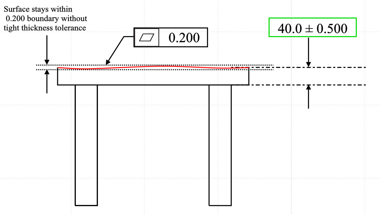
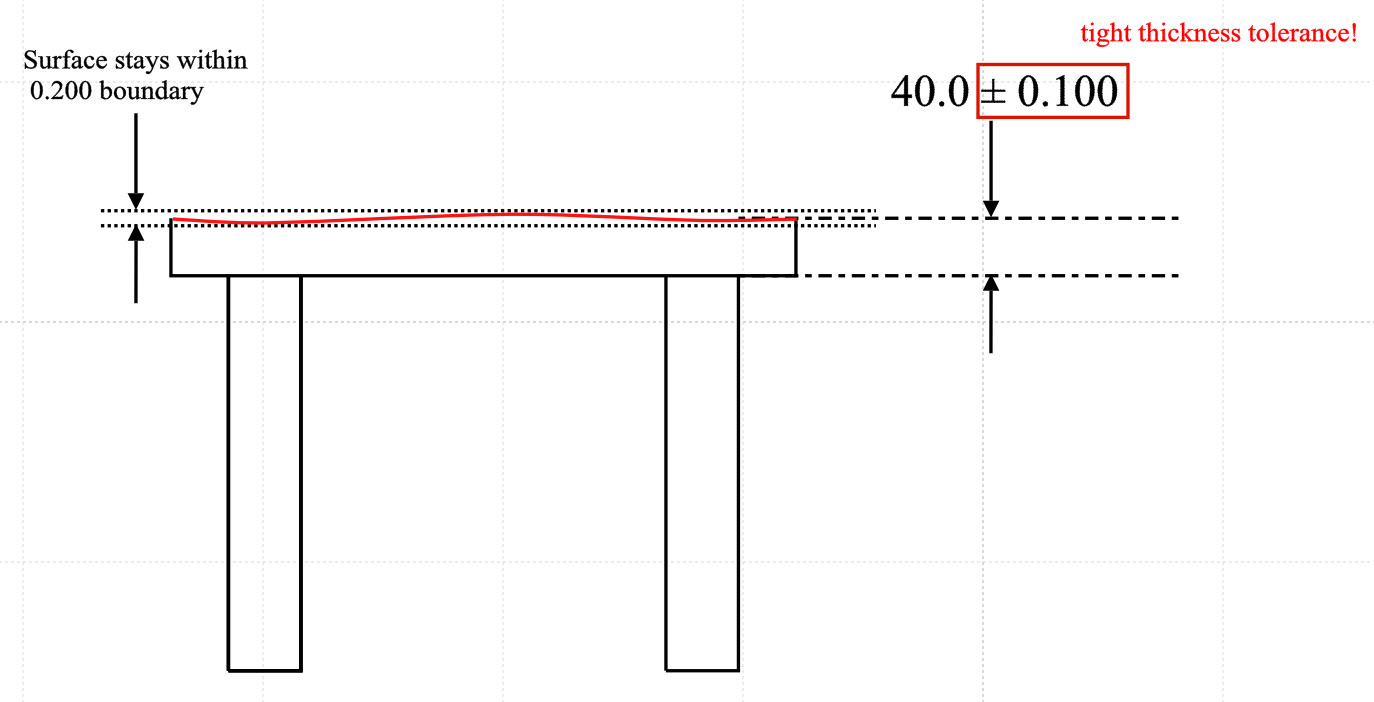
If you want to make sure that a tabletop is perfectly flat, if you did not have a flatness callout, you would have to constrain the height of the table very tightly to make sure that the entire surface is straight. With flatness, you can allow the table to be flat without constraining the tabletop thickness very tight. (You would be rejecting tables that were good thicknesses and normally in spec if using Geometric Dimensioning and Tolerancing.)
FYI – The derived median plane is the mid-point between a two point measurement. You would essentially be taking simultaneous measurements of both the upper and lower surfaces of a slot and the mid point between the upper and the lower would define your plane. It is this plane that you are controlling.
Hello, I have a drawing in which a 6 hole pattern has a positional tolerance of 0.05 reference to 3 datums which in this case are the typical three faces of the part. However the datums have a profile tolerance of 0.2. Could this be possible? Or due to the tight positional tolerance on the holes the datum surfcaces should also have a flatness surface requirement of 0.05 for the holes to be within tolerances? That will make the part quite expensive. Thanks
I was taught over forty years ago that the correct way to check flatness is to zero your surface to itself on three jacks, surface facing up and indicate over the surface. I was taught that using fixed stands checks parallelism not flatness. This was the method used at Hughes Aircraft in my day. Will someone please explain in a clear concise way the difference between these two methods?
Light absorbing fabricfor photography
The common zone is in reference to the ISO standard and not part of the ASME Y14.5 standard. I wish I could offer further insight, but as of current we are not offering guidance on the ISO standard. Keep checking back, we’re happy to answer any and all questions relating to the ASME standard.
A question about the above 3 column approach. Should you not look for the high point of the piece and measure from there. Rather than only level the piece?
Applying flatness to a surface, my customer says I need to add a circle i modifier next to the thickness tolerance to relieve the thickness from rule 1 “perfectly flat at MMC” looking for additional info on the “Circle I” thanks!
I ironed out this process before, on a granite table, use 3 jacks and level out as best you can. It will never be perfect (this is calculated out later). Then you use a digital height gauge with a retractable plunger like a Heidenhain. Measure all your points, log XYZ in Excel. -Use a plane-generator software (something free online) to generate the fit-plane equation for your dataset. Minus your Z measurements from each Z generated by that equation (this removes your TILT and isolates the face/plane you are measuring). You should have columns X Y Z Zeqn and (Z – Zeqn). -Take (Max-Min) of the last column, that’s your true flatness of that independent surface with tilt error removed from the calculation.
Take this to mean that a sufficient number of data points are taken with a probe on a DMM to adequately define a feature.
These are known as refinements. Your flatness is limited to 0.36 everywhere except between the holes where it must be at 0.08 (your thickness must still be met though.) The paralellism is simply stating how far off the orientation of the surface can be. (0.2 is a still a refinement of ±0.18 or 0.36 tolerance) You will need to measure each individually.
It’s specifying that you can’t have a flatness error greater than .005 for every square inch. You typically see this as a means to prevent abrupt changes in surface form. So, for instance, if you don’t require a particularly flat surface (say with a tolerance of .060), but also don’t want knife ridges due to the machinist using a hacksaw, you could create a composite control where you have .060 in the upper frame and .005/1×1 in the lower frame. You might check out section 5.4.2.2 of the ASME Y14.5 – 2009 standard for more information. I hope this helps clarify.
Another method of checking flatness is to do the following. Your inspection table has a hole in it just large enough to pass a dial indicator probe through. You place the surface you are checking for flatness in contact with both the inspection surface (and the dial indicator probe). As you move the part over the prove it will move up and down. This reading is telling you what your flatness error is.
Can flatness be used on multiple coincided surfaces? for instance on the four surfaces at the bottom of a 4 legged table. If the four surfaces could be seen as segments of a big surface, we could get away with only one notation.
You have hit the nail pretty well on the head. You’re measuring flatness correctly without the use of a CMM. The only other method that comes to mind is to have an inspection plate of suitable quality with a hole in the center. Your dial indicator extends through this hole and comes into contact with the part. After resetting the dial to zero you can move the part about randomly over the indicator and the max reading on the gage (full indicator movement) is the amount of flatness error in your part.
Regarding tolerance stacks, is the flatness added to the dimensional tolerance, or is the flatness included in the dimensional tolerance? The way you have it drawn, it looks like the table could be even taller than the dimensional tolerance when including the flatness.
Flatness is can be measured using a height gauge run across the surface of the part if only the reference feature is held parallel. You are trying making sure that any point along the surface does not go above or below the tolerance zone. Modern CMM’s are best for measuring the part as they can create virtual planes that the true surface profile can be compared to. This is a 3D measurement so points must be measured across the length and width of the part to ensure the entire surface is in tolerance. Flatness cannot be measured by simply placing the part on a granite slab and running a height gauge or microheight over it. This would be measuring parallelism instead as you are fixing the bottom of the part as a datum.
light absorbingblack-out material
Flatness is not the same as parallelism. Parallelism uses a datum to control a surface while flatness does not. Think of a table with two missing legs at an angle to the floor. The tabletop may be within flatness tolerance but would not be parallel to the floor.
Hey i just ran into an issue that i cant seem to find any definitive answer on, I was wondering if you have any insight. Ok i have a part with a .006 flatness call out, with out a CMM to measure this i use 3 jacks. 2 of them at opposites ends of one side and the other jack on the opposing side in the middle, then i level those points and go about checking my part and get a deviation of .01. Since my part is bowed, and two jacks are on the high side , and the other jack is on the low side my measurement is the amount the part is bowed X 2, When really the part is flat within .005. So my question is , is there any standard or answer to which points to use to level your part for checking flattness?
Is Flatness value will depend on the length of face? Any standard table recommended flatness value and corresponding face length
Flatness is the 3D version of surface straightness – Instead of the tolerance zone between two lines; the tolerance zone exists between two planes.
Thanks for the kind comments. We frequently get asked ‘What tolerance should I put on my drawing?’. The answer to that is honestly whatever you need it to be and absolutely no tighter than your design requires to function. Each design is unique and the requirements of one design don’t necessarily dictate the needs of another. I would highly encourage you to speak with others in your specific industry to get a feeling of where to start. In regards to seals and gaskets, you can often find requirements directly from the seal manufacture. They will recommend sizes and tolerances in many cases.
The datum is simply placed on the surface that the flatness tolerance is also called on. Other than also having flatness called on that surface, there is no other difference. Calling flatness on a datum surface can make sure that the datum is uniform and flat enough. Remember though – the is not flatness relative to the datum – it is simply both a datum, and a flatness callout.
All of the form controls (flatness, straightness, circularity and cylindricity) as well as general tolerance of size are governed by Rule #1. Meaning that, at the maximum material condition of the part perfect form is required. For example, if you have a plate that is .90 – 1.00 in size with no controls and the part is manufactured at 1.00 there can be no flatness error on the surface in question. It is only as your part departs towards LMC that any form error is permissible. If your part is made at .90 then your part can accept .10 worth of flatness error. It is also for this reason that any tolerance for a form control must be less than the size tolerance as Rule #1 has an inherent flatness/straightness/circularity/cylindricty control built into it.
Is it okay to put the Datum in flatness tolerance? What does it mean? I saw some drawing in my company. In connection from my first question, what’s the difference between placing datum in surface and in a flatness tolerance?
i have one question , not regarding the above. I have problem of perpendicularity issue . I have to mentain 0.0005″ (0.0125 mm) but my components resting face is 0.002″( 0.050 mm) . I am not getting value of pendicularity within 0.0005″ . question- Is it Ok the resting surface variation within 0.050 mm to mentain the perpendicularity between opposite face of resting face to bore length ( size 19 mm and length 50 mm) .


 Ms.Cici
 8618319014500