
Wratten 15 filter - The KAPtery - vratten
Changing the ocular lens magnification also impacts total magnification. With an objective lens at 40x and an ocular lens magnification adjusted to 20x, the resulting total magnification is 800x.
For many applications, such as holography, spatial intensity variations in the laser beam are unacceptable. Using precision pinholes in conjunction with positioning and focusing equipment such as our KT311(/M) Spatial Filter System creates a "noise" filter, effectively stripping variations in intensity out of a Gaussian beam. Please see the Tutorial tab for more information on spatial filters.
If you do not see what you need among our pinhole offerings, it is possible to special order pinholes that are fabricated from different substrate materials, have different pinhole sizes, incorporate multiple holes in one foil, or provide different pinhole configurations. Customized pinhole housings are also available. Please contact Tech Support to discuss your specific needs.
Below is a reflectance graph for the blackened stainless steel foils used in the circular precision pinholes. The raw reflectance data can be found here.
To calculate total magnification for traditional microscopes, locate the magnification power engraved on the microscope’s eyepiece and objective lens, often marked as numbers like 10x, 12.5x, etc. Multiply the magnification of the eyepiece by that of the objective lens. For instance, an eyepiece at 10x and an objective lens at 40x gives a total magnification of 400x.
Upon request, these pinholes are available with item-specific test reports at an additional cost. Please contact Tech Support for details.
In digital microscopy, total magnification depends on additional factors such as the video magnification which can be calculated on devices like computer monitors or TV monitors. For digital systems, use the formula: Total Magnification = Objective Magnification x Microscope Adapter Magnification x Video Magnification. An example of this could be an objective lens of 10x, a video coupler of 0.45x, and a video magnification of 60.3x, resulting in a total magnification of 271.35x.
The numerical aperture (NA) of an objective lens is crucial in defining its resolution capability. By calculating the minimum magnification using the formula 500 x NA, users can ensure they achieve the maximum resolution possible for their specimen details.
The stainless steel precision pinholes in Ø1/2" housings described above are available kits of ten. Each kit is shipped in a plastic storage case that protects the pinholes from damage.
To perform the calculation of total magnification, you require a microscope. This instrument typically includes multiple objective lenses and an ocular lens.
Pinhole lens
For example, suppose that you are using a 650 nm diode laser source that has a diameter (1/e2) of 1.2 mm and want your beam exiting the spatial filter system to be about 4.4 mm in diameter. Based on these parameters, the C560TME-B mounted aspheric lens would be an appropriate choice for the input side of spatial filter system because it is designed for use at 650 nm, and its clear aperture measures 5.1 mm, which is large enough to accommodate the entire diameter of the laser source.
Try Sourcetable for free and experience the ease of doing complex calculations without hassle. Sign up at app.sourcetable.com/signup.
Understanding how to calculate total magnification allows users to select the appropriate eyepiece and objective lens combinations. This ensures clear and detailed observations without empty magnification. For instance, combining a 10x eyepiece with a 40x objective lens results in a total magnification of 400x.
Upon request, these pinholes are available with item-specific test reports at an additional cost. Please contact Tech Support for details.
An example of the calculation with real-world figures would be using a 10X objective lens, a 0.45x microscope adapter, and video output to a 19-inch monitor with a 1/2 inch format CCD. Following the formula, compute 10 x 0.45 x 60.3 = 271.35. Thus, the total magnification achieved is approximately 271.35 times.
Effective calculation of total magnification enhances the quality of photomicrographs — photographs taken through a microscope. This calculation makes it possible to choose the proper magnification levels to clearly depict the molecular or cellular structures being documented.
If you do not see what you need among our stock pinhole and slit offerings, it is also possible to special order pinholes and slits that are made with different foil materials, have different hole sizes and shapes, incorporate multiple holes in one foil, or provide different hole configurations. Please contact Tech Support to discuss your specific needs. For more information on the properties of the bulk materials from which the pinholes are fabricated, see the table below.
Upon request, these pinholes are available with item-specific test reports at an additional cost. Please contact Tech Support for details.
How to make a pinhole camera
The foils can be taken out of their housings by removing the retaining ring using small tweezers or pliers; use care as the foil is very thin (50 µm).
Elliptical beam shapes can be undesirable, as the spot size of the focused beam is larger than if the beam were circular, and as larger spot sizes have lower irradiances (power per area). Techniques for circularizing an elliptical beam include those based on a pair of cylindrical lenses, an anamorphic prism pair, or a spatial filter. This work investigated all three approaches. The characteristics of the circularized beams were evaluated by performing M2 measurements, wavefront measurements, and measuring the transmitted power.
Discover the power of Sourcetable, an AI-driven spreadsheet that simplifies complex calculations. Whether for academics, work, or daily tasks, Sourcetable offers a seamless and efficient solution for computing and understanding results.
To calculate the total magnification of a basic compound microscope, multiply the magnification power of the objective lens by that of the ocular lens. For instance, if the ocular lens has a power of 10x and the objective lens has a power of 40x, the total magnification is 400x.
Understanding how to calculate total magnification is crucial for professionals and students in the fields of biology and microscopy. Total magnification is the product of the magnification of the objective lens and the magnification of the eyepiece. This concept can be calculated with a simple formula: magnification_objective × magnification_eyepiece.
In addition to single pinholes, Thorlabs also offers pinhole wheels that contain 16 radially-spaced pinholes that are lithographically etched onto a chrome-plated fused silica substrate. These wheels allow the user to test multiple pinhole sizes within a setup.
Upon request, these pinholes are available with item-specific test reports at an additional cost. Please contact Tech Support for details.
Some information describing selection and configuration procedures for several components used in this experimental work can be accessed by clicking the following hyperlinks:
Pinholes in Ø1" Housings can be mounted in a SM1ZM Zoom Housing and ST1XY-D XY Translator to provide fine positioning control in all three axes.
For optimal performance, a large-diameter aspheric lens can be used in place of a plano-convex lens if the necessary focal length on the output side is 20 mm (see AL2520-A, AL2520-B, AL2520-C). These lenses are 25 mm in diameter and can be held in place using the supplied SM1RR Retaining Ring.
The formula total magnification = objective magnification × ocular magnification is automatically applied by Sourcetable’s AI. The answer, with detailed steps, is promptly displayed in the spreadsheet and explained via a chat interface.
These unmounted precision pinholes are available with pinhole diameters from 2500 µm to 9000 µm. They are fabricated from stainless steel foils that are blackened on both sides. When handling the pinholes, please use small tweezers or pliers; use care as the foil is very thin (50 µm). These pinholes can be mounted in our SM05-Threaded Lens Tubes, secured between two retaining rings.
By centering a pinhole on a central Gaussian spot, the "clean" portion of the beam can pass while the "noise" fringes are blocked (see Figure 3 below).
The experimental results are summarized in the following table, in which the green cells identify the best result in each category. Each circularization approach has its benefits. The best circularization technique for an application is determined by the system’s requirements for beam quality, transmitted optical power, and setup constraints.
Material PropertiesDepending on the application, it can be important to consider the material properties of the pinhole or slit. The material used to construct the aperture can have varying levels of melting point, density, and thermal conductivity, as detailed in the table below.
These mounted precision pinholes are available with pinhole diameters from 1 µm to 9000 µm. They are fabricated from stainless steel foils that are blackened on both sides. The foils are mounted in 0.14" (3.6 mm) thick, black-anodized aluminum housings that have 0.10" (2.5 mm) deep SM1 threads. The SM1 threading of these pinholes provides direct compatibility with any other internally SM1-threaded mount, while the 1.20" (30.5 mm) housing outer diameter matches that of standard Ø1" lens tubes. The housing has a knurled outer edge for increased grip while screwing into or unscrewing out of another part by hand. For more precise control, two holes on the front of the housing accept the SPW801 or SPW909 spanner wrench. Each housing is engraved with the pinhole Item # and the size of the pinhole.
Pinhole in ophthalmology
These mounted precision pinholes are available with pinhole diameters from 1 µm to 9000 µm. They are fabricated from stainless steel foils that are blackened on both sides. The foils are mounted in Ø1", 0.10" (2.5 mm) thick aluminum housings that are black-anodized. Each housing is engraved with the pinhole Item # and the size of the pinhole.
It's crucial to ensure that the magnification does not exceed the system’s resolving power, which could lead to empty magnification—where no additional detail is visible. The numerical aperture (NA) of the objective lens also helps define the resolution and consequently the maximum useful magnification, calculated as 500 x NA. Always select eyepiece and objective combinations wisely to maintain the effectiveness of magnification while observing microscopic details.
Total magnification refers to the overall enlargement of an image observed under a microscope. It is derived from multiplying the magnifications of individual components within the optical path. This guide provides a detailed explanation on calculating the total magnification with clarity and precision.
Total magnification in microscopy is the product of the magnifications of the objective lens and the ocular or eyepiece lens. The formula is expressed as total magnification = objective lens power x ocular lens power. This value is crucial for viewing small details under a microscope.
The correct optics and pinhole for your application depend on the input wavelength, source beam diameter, and desired exit beam diameter.
The experimental setup is shown in Figure 1. The elliptically-shaped, collimated beam of a temperature-stabilized 670 nm laser diode was input to each of our circularization systems shown in Figures 2 through 4. Collimation results in a low-divergence beam, but it does not affect the beam shape. Each system was based on one of the following:
Yes, the total magnification in digital microscopy can be calculated using the ratio of the size of the image on the monitor to the size of the image on the sensor, involving the width or height of the image.
Understanding how to calculate total magnification is essential for professionals and students in the fields of biology and microscopy. Total magnification determines how much larger an object appears under a microscope compared to its actual size. It involves a simple multiplication of the magnification power of the objective lens by the magnification power of the eyepiece lens. This calculation allows for a precise analysis of microscopic elements, enhancing both academic and professional practices.
Precision Pinhole OptionsThorlabs' precision pinholes are available with an assortment of fabrication materials and coatings. The choice of a particular size and material should depend on the application. Low-power applications may benefit more from the absorbance of our blackened stainless steel foils, which are offered in anodized-aluminum housings, or our stainless steel foils with a black PVD coating, which are offered in vacuum-compatible stainless steel housings. High-power applications may need the high damage threshold and reflectance of gold-plated copper foils, the high melting point and lower reflectance of our tungsten foils, or the high melting point of our molybdenum foils paired with the low reflectance (4% @ 800 nm) of their black-coated front side. Please see the Foil Comparison and Graph tabs for more information.
Components used in each circularization system were chosen to allow the same experimental setup be used for all experiments. This had the desired effect of allowing the results of all circularization techniques to be directly compared; however, optimizing the setup for a circularization technique could have improved its performance. The mounts used for the collimating lens and the anamorphic prism pair enabled easy manipulation and integration into this experimental system. It is possible that using smaller mounts would improve results by allowing the members of each pair to be more precisely positioned with respect to one another. In addition, using made-to-order cylindrical lenses with customized focal lengths may have improved the results of the cylindrical lens pair circularization system. All results may have been affected by the use of the beam profiler software algorithm to determine the beam radii used in the circularity calculation.
Pinhole camera model
To calculate the total magnification in digital setups more accurately, use the ratio of the image size on the monitor to the size of the image on the sensor. This can be referred to using a simple dimension like width or height, ensuring a standardized calculation is used.
Sourcetable, an AI-powered spreadsheet, dramatically simplifies the process of performing various calculations, including total magnification. Its intuitive interface and robust capabilities make it an ideal choice for managing and analyzing AI-generated data, enhancing both accuracy and efficiency.
Pinhole optics
For digital microscopy, the total magnification depends on the size of the image displayed on the monitor, in addition to the magnifications provided by the microscope's optics.
Total magnification in microscopy isn't only about the equipment but also about the digital display. For digital microscopes, the total magnification is influenced by the optical resolution, the resolution of the image sensor, and the resolution of the image display. The interaction between these factors determines the clarity and utility of the magnified image.
For digital microscopes, total magnification might include an additional digital zoom factor. If the optical magnification is 500x and the digital zoom is set to 2x, the total effective magnification would be 1000x.
The foils can be taken out of their housings by removing the retaining ring using small tweezers or pliers; use care as the foil is very thin (50 µm).
For this focal length, we recommend the LA1131-B plano-convex lens [with f = 50 mm at the design wavelength (λ = 633 nm), this is still a good approximation for f at the source wavelength (λ = 650 nm)].
Precision Pinholes and SlitsThorlabs offers precision pinholes with blackened stainless steel, gold-plated copper, tungsten, or molybdenum foils. Our pinholes with stainless steel foils are blackened on both sides for increased absorbance and are available from stock in circles from Ø1 µm to Ø9 mm and squares from 100 µm x 100 µm to 1 mm x 1 mm. Our stainless steel pinholes with a black PVD coating are vacuum compatible and available in 5 μm to 2 mm diameters. Our pinholes with gold-plated copper foils, plated with gold on one side and black PVD coated on the reverse, are available with pinhole diameters from 5 µm to 2 mm. High-power gold-plated copper foil pinholes are also available, with the gold-plated copper foil on the front face, and a PVD black coating on the rear. Our pinholes with tungsten foils are uncoated and available with pinhole diameters from 5 µm to 2 mm. Lastly, our pinholes with molybdenum foils have an absorptive polymer coating on the front sides and are available with pinhole diameters from 5 µm to 2 mm. We also offer slits in blackened stainless steel foils from stock with slit widths from 5 to 200 µm.
Single precision pinholes offer optical apertures for applications such as alignment, beam conditioning, and imaging. The Ø1 µm to Ø9000 µm pinholes below are in blackened stainless steel foils, with select sizes available unmounted or mounted in black-anodized aluminum housings (Ø1/2", SM05 threaded, Ø1", or SM1 threaded). Our stainless steel pinholes mounted in Ø1/2" or Ø1"unthreaded housings are also available in kits. We offer pinholes with a variety of other foil materials; see the table to the right for options.
Understanding magnification calculations facilitates the comparison of specimens under different magnifications. This is essential in fields like pathology or microbiology where detailed cellular analysis is required across various magnification levels.
The input Gaussian beam has spatially varying intensity "noise". When a beam is focused by an aspheric lens, the input beam is transformed into a central Gaussian spot (on the optical axis) and side fringes, which represent the unwanted "noise" (see Figure 2 below). The radial position of the side fringes is proportional to the spatial frequency of the "noise".
Pinhole test
While it was demonstrated that each circularization technique improves the circularity of the elliptical input beam, each technique was shown to provide a different balance of circularization, beam quality, and transmitted power. The results of this work, which are documented in this Lab Fact, indicate that an application's specific requirements will determine which is the best circularization technique to choose.
This webpage provides a step-by-step guide on calculating total magnification effectively. Additionally, we'll explore how Sourcetable's AI-powered spreadsheet assistant enhances these calculations. By integrating advanced computational tools, Sourcetable simplifies complex data tasks, making it an invaluable resource for scientific calculations. Experience the efficiency of Sourcetable by signing up at app.sourcetable.com/signup.
Sourcetable takes the math out of any complex calculation. Tell Sourcetable what you want to calculate. Sourcetable AI does the rest. See the step-by-step result in a spreadsheet and visualize your work. No Excel skills required.
Pinhole camera Class 6
Calculate total magnification seamlessly using Sourcetable. Simply input the magnification of the objective lens and the ocular lens into the spreadsheet. For instance, if the objective lens is 40x and the ocular lens is 10x, place them in individual cells. Ask Sourcetable, “How to calculate total magnification?” and it will compute the product of these values.
For many applications, such as holography, spatial intensity variations in the laser beam are unacceptable. Our KT311 spatial filter system is ideal for producing a clean Gaussian beam.
Upon request, these pinholes are available with item-specific test reports at an additional cost. Please contact Tech Support for details.
These mounted precision pinholes are available with pinhole diameters from 1 µm to 2000 µm. They are fabricated from stainless steel foils that are blackened on both sides. The foils are mounted in Ø1/2" (12.7 mm), 0.10" (2.5 mm) thick aluminum housings that are black-anodized. Each housing is engraved with the pinhole Item # and the size of the pinhole.
By correctly calculating the necessary magnification, users avoid empty magnification, which results in increased image size without additional detail. This ensures efficient and meaningful magnification in microscopic analysis.
Edge-emitting laser diodes also emit astigmatic beams, and it can be desirable to force the displaced focal points of the orthogonal beam components to overlap. Of the three circularization techniques investigated in this work, only the cylindrical lens pair can also compensate for astigmatism. The displacement between the focal spots of the orthogonal beam components were measured for each circularization technique. In the case of the cylindrical lens pair, their configuration was tuned to minimize the astigmatism in the laser beam. The astigmatism was reported as a normalized quantity.
It is important to note that the front of the gold-plated copper foil circular precision pinholes have a low-reflectance PVD black coating. The rear of these pinholes leaves the gold-plated copper foil bare. This also occurs on the molybdenum foil circular precision pinholes, which have a low-reflectance absorptive polymer coating on the front and the molybdenum foil is left bare on the back.
This feature is not only convenient but also educational, making Sourcetable an excellent tool for students and professionals needing precise and clear explanations of complex calculations.
Using the same microscope with a different objective lens magnification alters the total magnification. If the ocular lens remains at 10x, but the objective lens is 100x, the total magnification becomes 1000x.
Reflectance The reflectance of the foil material or coating affects performance in a variety of applications. Below is presented a reflectance graph for all the materials and coatings that are offered with our circular and square precision pinholes, as well as our mounted optical slits. The raw reflectance data can be found here.
The pinhole should be chosen so that it is approximately 30% larger than D. If the pinhole is too small, the beam will be clipped, but if it is too large, more than the TEM00 mode will get through the pinhole. Therefore, for this example, the pinhole should ideally be 19.5 microns. Hence, we would recommend the mounted pinhole P20D, which has a pinhole size of 20 μm. Parameters that can be changed to alter the beam waist diameter, and thus the pinhole size required, include changing the input beam diameter and focal length of focusing lens. Decreasing the input beam diameter will increase the beam waist diameter. Using a longer focal length focusing lens will also increase the beam waist diameter.
Spatial filtering significantly improved the circularity and quality of the beam, but the beam had low transmitted power. The cylindrical lens pair provided a well-circularized beam and balanced circularization and beam quality with transmitted power. In addition, the cylindrical lens pair compensated for much of the beam's astigmatism. The circularity of the beam provided by the anamorphic prism pair compared well to that of the cylindrical lens pair. The beam output from the prisms had better M2 values and less wavefront error than the cylindrical lenses, but the transmitted power was lower.
The foils can be taken out of their housings by removing the retaining ring using small tweezers or pliers; use care as the foil is very thin (50 µm).
The equation for diffraction limited spot size at the 99% contour is given above, and for this example, λ = (650 x 10-9 m), f = 13.86 mm for the C560TM-B, and r = 0.6 mm. Substitution yields
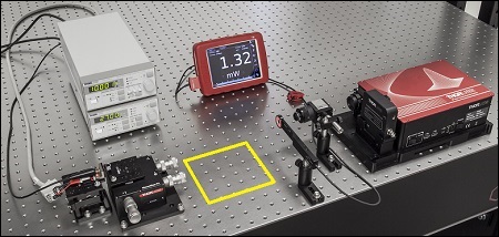
The characteristics of the beams output by the different circularization systems were evaluated by making measurements using a power meter, a wavefront sensor, and an M2 system. In the image of the experimental setup, all of these systems are shown on the right side of the table for illustrative purposes; they were used one at a time. The power meter was used to determine how much the beam circularization system attenuated the intensity of the input laser beam. The wavefront sensor provided a way to measure the aberrations of the output beam. The M2 system measurement describes the resemblance of the output beam to a Gaussian beam. Ideally, the circularization systems would not attenuate or aberrate the laser beam, and they would output a perfectly Gaussian beam.
The beam circularization systems, shown to the right, were placed, one at a time, in the vacant spot in the setup highlighted by the yellow rectangle. With this arrangement, it was possible to use the same experimental conditions when evaluating each circularization technique, which allowed the performance of each to be directly compared with the others. This experimental constraint required the use of fixturing that was not optimally compact, as well as the use of an unmounted anamorphic prism pair, instead of a more convenient mounted and pre-aligned anamorphic prism pair.
Edge-emitting laser diodes emit elliptical beams as a consequence of the rectangular cross sections of their emission apertures. The component of the beam corresponding to the narrower dimension of the aperture has a greater divergence angle than the orthogonal beam component. As one component diverges more rapidly than the other, the beam shape is elliptical rather than circular.
These mounted precision pinholes are available with pinhole diameters from 1 µm to 2000 µm. They are fabricated from stainless steel foils that are blackened on both sides. The foils are mounted in 0.14" (3.7 mm) thick, black-anodized aluminum housings that have 0.10" (2.5 mm) deep SM05 threads. The SM05 threading of these pinholes provides direct compatibility with any internally SM05-threaded mount, while the 0.70" (17.8 mm) housing outer diameter matches that of a standard Ø1/2" lens tube. The housing has a knurled outer edge for increased grip while screwing into or unscrewing out of another part by hand. For more precise control, two holes on the front of the housing accept the SPW801 or SPW908 spanner wrench. Each housing is engraved with the pinhole Item # and the size of the pinhole.
Pinhole camera
For more technologically advanced systems that input to TV monitors or cameras, the formula adjusts to incorporate additional components. Here, it includes objective magnification, microscope adapter magnification, and video magnification and is represented as total magnification = objective magnification x microscope adapter magnification x video magnification. Video magnification computes as the ratio of the monitor's diagonal size to the CCD chip's diagonal measured in millimeters.
Knowing how to calculate total magnification supports educational endeavors and research activities by helping to correctly document and share microscopic findings. Accurate magnification notation aids others in replicating experiments or understanding complex visual data.
Finally, we need to choose the optic on the output side of the spatial filter so that the collimated beam's diameter is the desired 4.4 mm. To determine the correct focal length for the lens, consider the following diagram in Figure 4, which is not drawn to scale. From the triangle on the left-hand side, the angle is determined to be approximately 2.48o. Using this same angle for the triangle on the right-hand side, the focal length for the plano-convex lens should be approximately 50 mm.
The foils can be taken out of their housings by removing the retaining ring using small tweezers or pliers; use care as the foil is very thin (50 µm).
The stainless steel precision pinholes in Ø1" housings described above are available kits of ten. Each kit is shipped in a plastic storage case that protects the pinholes from damage.


 Ms.Cici
 8618319014500