
USB A-Male to USB Micro-B Cable - 6 inches - cable usb a micro b
Aberrations5e
Contents other than in English and Japanese are machine translated for your reference purposes only.The accuracy of the machine translation cannot be guaranteed.Please use this site with the understanding that automatic translation is not 100% accurate.
Aberrationsin optics
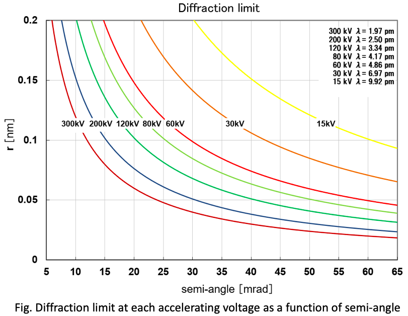
Figure shows the diffraction limit (vertical axis) r = 0.6λ/sinα for each accelerating voltage as a function of divergence semi-angle α. Since the wavelength of an electron beam is longer for the lower accelerating voltage, the diffraction limit r becomes larger for the lower accelerating voltage even for the same semi-angle α. In the case of an accelerating voltage of 200 kV, a resolution of 0.1 nm expected from the diffraction limit is achieved with a divergence semi-angle of approximately 15 mrad. In the case of 80 kV, however, a larger divergence semi-angle of an approximately 25 mrad is required because of a longer wavelength of the electron beam.
Aberrationsexamples

The diffraction limit is the resolution limit due to diffraction of an electron wave for the optical system with no aberrations. Even in the aberration-free optical system, electron waves exiting from one point on the object do not form an infinitesimal point on the image plane but these electron waves are focused into a finite size spot (airy disk) due to their diffraction phenomenon. The radius r of the airy disk is given by the equation r = 0.6λ/sinα, where λ is the wavelength of the electron and α is the divergence angle of the electron. From the equation, it is seen that the size of the airy disk is small for a large divergence angle of the electron beam. This limitation makes it impossible to produce an infinitesimal point resolution even for ideal lenses.


 Ms.Cici
 8618319014500