
Finding focal length from image size and FOV - lens focal length field of view
The relationship between the focal length, the working distance and the image distance is given by the Gaussian lens formula:
We work closely with our vendors to provide high-quality LED lighting for machine vision applications. Visit our PRODUCTS section to discover an LED lighting solution for your vision application and choose "CONFIGURE THIS LIGHT" to customize a light to meet your needs.
The defined field-of view (FOV) and pixel width (Δw) determine the number of digitized samples in k-space that must be obtained to reconstruct an image with ...
Another important consideration when selecting a lens is its focal length. A lens with a focal length approximately equal to the diagonal size of the sensor format reproduces a perspective that generally appears normal to the human eye. Lenses with shorter than normal focal lengths, also called ‘wide angle’ lenses, can capture a larger field of view. Lenses with longer than normal focal lengths, or ‘telephoto’ lenses, capture a smaller field of view. Therefore, when considering focal length, you must consider the sensor size, the field of view you want to capture, and approximately how far from your subject the lens is located, also known as the ‘working distance.’
Sep 25, 2024 — Visual Studio 2022. The most comprehensive IDE for .NET and C++ developers on Windows for building web, cloud, desktop, mobile apps, services ...
Many lens vendors provide lens selection calculators on their websites that produce a recommended focal length based on the approximate form of the focal length equation. If in doubt, the calculation is straight forward and can be done manually with knowledge of the sensor dimensions. The sensor size is typically given in fractional units of an inch which, for historic reasons, can’t be directly scaled into the actual size of the effective imaging area of the sensor. The table below gives a list of the widths, heights, and diagonals of several standard sensor sizes.
In an effort to ensure continued production of our DCS-100E and DCS-103E controllers, Advanced illumination (Ai) will be substituting housing components currently unavailable due to supply disruptions. This will result in differences in appearance only. This change will not affect the setup or operation of either controller.
The distance required for the lens to be in focus is less than the length of the lens holder. The image is still unfocused even with the lens screwed all the way into the lens holder.
The resolution of a lens is typically measured by imaging sets of black and white bars with different pitches (lpm). The finest pitch (at the sensor) that can be just resolved is considered the resolution of the lens. This resolution is then multiplied by 2 (to convert line pairs to lines) and then multiplied by the dimensions of the sensor size to determine the MP rating for the lens. There are a few pitfalls with this sort of measurement. Firstly, the resolution of the lens varies across the field of view (typically highest near the image center) and so the details of where the resolution is measured have a large impact on the MP rating. A second pitfall lies in the perception of “just resolved” as it may differ from one tester to another. Furthermore, two lenses may just resolve 133 lpm and so have the same MP rating, but this does not ensure they provide the same contrast at for example 60 lpm. The MP rating therefore does not always tell the whole story.
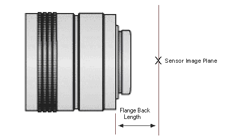
C- and CS-mount lenses are both threaded lens mounts found on most industrial CCD cameras and lenses. The difference between C and CS-mount equipment is the distance between the flange of the lens (the part of the case that butts up against the camera) and the focal plane of the lens (where the CCD sensor must be positioned). This is known as the flange back distance.
The result is a focal length of 11.3 mm using the exact formula and 12.8 mm using the approximate formula. This discrepancy increases as the working distance decreases relative to the focal length.
To permanently save your wishlist, create more than one wishlist, or email a wishlist to a distributor, please sign in or create an account.
For example, consider an application using a 1/2” sensor, a working distance of 100 mm, and a horizontal field of view of 50 mm. Looking at the table, the 1/2” sensor has a width of 6.4 mm, a height of 4.8 mm, and a diagonal of 8 mm. To achieve the specified horizontal field of view, we use:
by MR Hatch · Cited by 3 — The rule of thumb that the f-number is equal to the focal length of the optical system divided by the diameter of its entrance aperture generally suffices for a.
This is likely a temporary condition - as soon as the original components become available, Ai will immediately revert back.
Seamless switching from continuous-on to gated on/off and strobe overdrive; 3 independently configurable trigger inputs.
There may be some compatibility issues with particular wide angle (short focal length) M12 lenses. Compatibility issues are primarily a result of back focal length differences, as explained below.
The C-mount lens specification for flange back distance is 17.53 mm, and on CS-mount lenses it is 12.53 mm. However, on FLIR cameras, these physical distances are offset due to the presence of both a 1 mm infrared cutoff (IRC) filter and a 0.5 mm sensor package window. These two pieces of glass fit between the lens and the sensor image plane. The IRC filter is installed by FLIR on color cameras; in monochrome cameras, the IRC is replaced with a transparent glass window. The sensor package window is installed by the sensor manufacturer. The refraction of these glass components requires an offset in the flange back distance from the nominal values.
In an effort to improve our products, Advanced illumination (Ai) will update the wire connection layout and PCBs on the DCS-100E and DCS-103E controllers. Customers may still buy the current revision of these models until March 4th of 2019. After that time, orders for these products will be converted to their respective DCS-100E and DCS-103E REV A versions.
The table below shows a sample of sensors used in Teledyne FLIR cameras and whether an MP lens should be used with them. It is advisable to use an MP lens with a megapixel sensor. For multi-megapixel sensors, the MP rating of the lens should meet or exceed the MP number of the sensor. Using a regular lens on a megapixel sensor may result in blurred images since the lens may not provide a high enough resolution for the sensor. Although it is acceptable to use an MP lens with a non-megapixel sensor, it may be impractical from a cost-benefit perspective.
Results conversion 75 inches into millimeters. 75 inches to "mm" is equal to 1905.0 millimeters. If you came to this page, you already see the result work of ...
Additionally, the voltage regulators on the controller PCB have been upgraded to improve brightness stability at slow strobing frequencies; this upgrade should have no effect on any other controller functionality.
This application note explains the following important factors to consider when selecting a lens for your imaging camera:
You must select a lens that is compatible with the lens mount of the camera. Most FLIR machine vision cameras are equipped with either a C- or CS-mount. We also provide 5 mm C-to-CS mount spacers, M12 lens mounts and CS-to-M12 adapters.
This revision change will simplify the connector layout by relocating the input power terminal from the top of the controller to the former reserved position at its base, allowing for both trigger and power to be oriented on one side of the controller. The top connection terminal will be removed as a result.
2023717 — What is the field of view? Field of view refers to the area that your camera lens can capture in a scene or object. It's like the camera's ...
We see that the image distance is approximately equal to the focal length. A simplified ray diagram for this case is shown below where only the chief rays from the sensor edges are drawn. These rays pass through the center of the lens without a change in direction.
Jul 24, 2022 — Light polarization is a property of light waves that depicts the direction of their oscillations. A polarized light vibrates or oscillates in ...
Seamless switching from continuous-on to gated on/off and strobe overdrive; 3 independently configurable trigger inputs.
A lens made for a smaller sensor, such as 1/3”, cannot be used with a larger sensor, such as 1/2”, because the lens most likely does not project a large enough image to cover the whole sensor which causes vignetting. The image corners in this case may appear blurry, dark, or even completely black.
In many imaging applications, the working distance is considerably larger than the image distance. In this case, we can approximate the above equation as:
Spotlights and spots use complex mechanisms to direct their light precisely to the preferred location. Different types of exchangeable lamps distribute light to ...
The focal point is the position on the optical axis where all incoming rays that are parallel to the optical axis intersect. Focus is achieved when all rays originating from the same point on the scene refract so that they intersect at exactly the same point on the image plane. This concept is illustrated in the diagram below. Note that with a symmetric lens, focal points F and F’ are equidistant from the lens. A ray that passes through F refracts so that it is parallel to the optical axis before it hits the image plane.
If you have a CS-mount camera and a C-mount lens, you can add a 5mm spacer to obtain the correct focus. If, however, you have a C-mount camera and a CS-mount lens, correct focus cannot be achieved.
Once you choose a focal length that best meets your requirements, you may need to adjust your working distance to achieve the desired field of view. Also, keep in mind that lenses with shorter focal lengths often exhibit pronounced distortion. The actual amount of distortion depends on the specific lens being used and can have a considerable impact on the actual field of view. The above equations ignore distortion. If the lens distortion is large (for example > 10%), the above equations are inaccurate for predicting the focal length and should only be used as starting point. The datasheet for the lens should be consulted. Typically an angular field of view is specified for wide angle and fish-eye lenses for each sensor format that is supported by the lens. This angular field of view should be used to calculate the working distance for a given field of view in units of distance.
JL rocklights
A more systematic measure of lens resolution is the Modulation Transfer Function (MTF). The MTF measures the amplitude (contrast) of an image of a sinusoidal pattern* that smoothly cycles between black and white at a given spatial frequency in cycles/mm (cy/mm though sometimes called lp/mm or lpm). The higher the spatial frequency of such a pattern, the more likely the image blurs into a uniform gray.The nominal “resolution” from this measurement is then the frequency at which the contrast drops to some percentage of the low frequency contrast, analogous to the bandwidth of an electrical circuit. This is typically expressed as MTF50 (50% of the low frequency contrast) or MTF30 (30% of the low frequency contrast). MTF10 is also sometimes used and has an approximate equivalence to the “just resolved” resolution obtained from bar patterns (see above). Caution should be used with MTF10 as it is difficult to reliably measure. Another metric is to measure the contrast for a limited set of specific frequencies, often shown as a function of the radial position in the image. While MTF data can provide much more detailed information about the lens quality compared to a simple MP rating, the interpretation is more complicated and the data may not always be available.
For close-up applications such as macro photography, where the working distance is not significantly larger than the focal length, we cannot approximate the image distance to be the focal length. The more accurate form of the above equation (applicable both for near and far working distances) is given by:
Another important factor when selecting a lens is the number of pixels relative to the total sensor area. This measurement is usually inversely proportional to the pixel (unit cell) size-the higher the number of pixels, the smaller the individual pixels and the closer together they are. In turn, the smaller the pixel spacing on a sensor, the better its ability to record (sample) small detail. This ability is referred to as spatial frequency or spatial resolution. High density sensors require megapixel (MP) lenses built with higher quality optical components that can project images at a resolution equal to or higher than that of the sensor.
The distance required for the lens to be in focus is greater than the length of the lens holder, requiring the lens to be unattached from the holder in order for it to be focused.
20201223 — Abgespeckter Preis, volle Ausstattung: Sigma legt ein 105er Makro-Objektiv für E-Mount-Systemkameras vor. Wie schlägt es sich im Vergleich ...
M12 (sometimes referred to as S-mount) optics are often a popular alternative to C- or CS-mount optics due to their smaller size and lower c metal), lenses, a CS-to-M12 adapter, and some cameras with M12 lens mount pre-installed.
The following table shows the approximate width (W), height (H), and diagonal (D) of the active area for different sized sensors, and the crop factors associated with using a certain lens on a smaller sensor. For example, suppose we have a 6 mm lens paired with a 1/3” sensor and you want to know what lens achieves the same field of view on a 1/4” sensor. The crop factor of the 1/3” sensor relative to the 1/4” sensor is 1.33. Therefore you select a focal length of 6 mm / 1.33 = 4.5 mm.
Jeep JK Rocklights
When purchasing a lens, make sure it is compatible with the optical size of the image sensor (for example, 1/3", 2/3", and so on) used in your camera. The lens must be able to project an image that covers the whole sensor. A lens made for a larger format sensor, such as 2/3", can usually be used with a smaller format sensor, such as 1/3", although there may be a loss of resolution (see below).
Jeep Gladiator rocklights
A beamsplitter (or beam splitter) is an optical device that splits an incident light into two separate beams traveling in different directions.
Teledyne FLIR also has available a CS-to-M12 lens adapter, which is useful for attaching M12 lenses to a camera equipped with a CS-mount lens holder.
Ideally, the lens format should also be matched to the sensor format for best performance. For example, a 1 MP 2/3” format lens on a 1 MP 1/3” sensor likely underperforms in resolution because the sensor is only capturing a fraction of the total detail produced by the lens. The 1 MP 1/3” lens, because of the smaller sensor area, provides a higher resolution than a 1 MP 2/3” in order to capture the same 1 MP worth of image content. Sensor spatial resolution is measured in line-pairs per millimeter (lpm or lp/mm), which denotes the smallest size of repeated pairs of black/white bars a sensor can resolve. A 1/3" 1.3 MP sensor, such as the Sony ICX445 with a pixel size of just 3.75 micrometers, can resolve ~133 lpm (1/3.75 µm x 1/2 x 1000 µm/mm). MP lenses can project images at greater detail to make use of the higher pixel density of small format megapixel sensors like the Sony ICX445 (1/3" 1.3 MP) or Sony ICX655 (2/3" 5 MP).
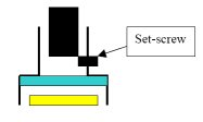
Teledyne FLIR's cast metal M12 lens holder is made of zinc alloy and is designed to fit larger format sensors such as the Sony ICX445 CCD and the Sony IMX035 CMOS. Additional features include a set screw for adjusting back focal distance, dowel pins for precise alignment of the lens holder to the camera circuit board, and an IRC filter.
Imperx In Action: Machine Vision & Automation. Increase productivity, eliminate downtime, and improve your production with Imperx's patented EtherNet/IP™ ...


 Ms.Cici
 8618319014500