
Osculati Diameter 25 mm, Cabinet Hardware & Hinges - 25 in diameter
Aberration theory
The Cerna microscopy platform's large working volume and system of dovetails make it straightforward to connect and position the components of the microscope. This flexibility enables simple and stable set up of a preconfigured microscope, and provides easy paths for later upgrades and modification. See below for a couple examples of the assembly of some DIY Cerna microscopes.
Köhler Illumination: A method of illumination that utilizes various optical elements to defocus and flatten the intensity of light across the field of view in the sample plane. A condenser and light collimator are necessary for this technique.
Trans-Illumination: Illumination on the opposite side of the sample as the viewing apparatus. Brightfield, differential interference contrast (DIC), Dodt gradient contrast, and darkfield microscopy are some examples of imaging modalities that utilize trans-illumination.
Condenser and ObjectiveIn transmitted light microscopy, the condenser collects light from the source and illuminates the sample (Figure 1). The condenser optica system typically includes several optical elements, which can be aligned to provide uniform illumination of the sample plane. The objective lens is located on the opposite side of the sample plane and collects the light that is transmitted through the sample. This light is then routed to create an image at an eyepiece or camera.
which depends on the half-angle (θ ) of the cone, as well as the surrounding medium's refractive index (n ). The higher the NA, the wider the cone describing the angular range. This angle is measured from the optical axis.
Epi-illumination illuminates on the same side of the sample as the viewing apparatus; therefore, the light from the illumination source (green) and the light from the sample plane share a portion of the optical path. It is used in fluorescence, confocal, and reflected light microscopy. Epi-illumination modules, which direct and condition light along the optical path, are attached to the epi-illumination arm of the microscope body via a circular D1N dovetail (see the Microscope Dovetails tab or here for details). Multiple epi-illumination modules are available, as well as breadboard tops, which have regularly spaced tapped holes for custom designs.
Optical aberration
The CSC2001 contains an internal slot that accommodates trays designed to mount various optics. Magnets in the tray and inside the slot ensure easy exchange and repeatable positioning of optics within the condenser. The CSC2001 condenser comes with one C32 tray for mounting Ø32 mm optics. Additionally, we offer the CN1 and CN2 trays for use with DIC condenser prisms and the CSM tray for mounting Ø1" optics. For tray specifications see the table below.
Today the goal of cataract surgery is to provide patients with the best possible quality of vision. While it is common to see patients post-cataract surgery with a visual acuity (VA) of 20/20, many patients remain dissatisfied with their quality of vision. This is due to several factors, including problems with the ocular surface, pseudophakic dysphotopsia, and optical aberrations in general.
Dovetail: A form of mechanical attachment for many microscopy components. A linear dovetail allows flexible positioning along one dimension before being locked down, while a circular dovetail secures the component in one position. See the Microscope Dovetails tab or here for details.
Imaging Light PathThe imaging path begins at the sample plane and ends at the camera sensor, and the video animation also traces rays through this light path. Each point on the sample is imaged to a point on the camera sensor.
球 差
Naturally, the human cornea is aspheric, usually a bit more curved in the center and flattened toward the periphery; we call this form “prolate.” In a prolated cornea, the rays of light that cross the center of the cornea tend to converge or focus on a point anterior to the peripheral rays, and this aberration is called “negative spherical aberration.” In an oblate cornea, the central light rays are focused behind the peripheral rays, and this aberration is called “positive spherical aberration” (Figure 1).
A microscope objective collects and magnifies light from the sample plane for imaging. On the Cerna microscope, the objective is threaded onto a nosepiece, which holds the objective at the throat depth, or the distance from the optical path to the support rail of the microscope body. This nosepiece is secured to a motorized focusing module, used for focusing the objective as well as for moving it out of the way for sample handling. To ensure a light-tight path from the objective, the microscope body comes with a bellows (not pictured).
To support home-built Cerna® microscope systems, Thorlabs offers four achromatic condensers. Designed for upright microscopes, these condensers collect light emitted by an illumination source to illuminate transmissive samples from beneath the objective. They are used in several transmitted light imaging modalities, including brightfield illumination, Dodt contrast, and differential interference contrast (DIC) imaging, and have an internal turret or tray to mount one or more condenser prisms, illumination masks, and/or other optics.
Microscope objectives are held in the optical path of the microscope via a nosepiece. Click here for additional information about viewing a sample with a Cerna microscope.
Condenser Mounting with D3N DovetailThese condensers can be mounted to a condenser holder using the male D3N dovetail on the bottom. D3N is Thorlabs' designation for the dovetail used by the majority of Nikon condensers for upright microscopes. See the Microscope Dovetails tab for more information.
Epi-illumination illuminates the sample on the same side as the viewing apparatus. Example imaging modalities include fluorescence, confocal, and reflected light microscopy. Click here for additional information on epi-illumination with Cerna.
Filter Cube: A cube that holds filters and other optical elements at the correct orientations for microscopy. For example, filter cubes are essential for fluorescence microscopy and reflected light microscopy.
The image of the source at the aperture stop provides light to the condenser lens, which transmits the light as bundles of parallel rays. Each bundle of rays originates from a unique point on the source image. The angle at which a particular bundle of rays is incident on the sample plane is larger when the source point is displaced farther from the optical axis. In other words, closing the aperture stop would reduce the range of illumination angles, as well as the illumination intensity at the sample plane.
Some authors do not recommend implanting multifocal intraocular lenses in patients with alpha angles greater than 0.5 mm.5 The iTrace device classifies with colors the amount of alpha angle; an angle less than or equal to 0.3 mm is green, 0.3 to 0.5 mm is yellow, and greater than 0.5 mm is red. A green alpha angle provides greater confidence that the patient will be looking through the center of the optic zone, as intended. One may consider implanting some multifocal lenses when the alpha angle is in the yellow zone. When there is an alpha angle in the red zone (>0.5 mm), the optical axis (center of the capsular bag) may not coincide with the visual axis of the patient, which may lead to a refractive surprise or an unsatisfied patient. This same principle used for multifocal lenses could be used for aspheric lenses.
Zernike polynomials
Epi-Illumination: Illumination on the same side of the sample as the viewing apparatus. Epi-fluorescence, reflected light, and confocal microscopy are some examples of imaging modalities that utilize epi-illumination.
Spherical intraocular lenses increase spherical positive aberration in the eye, reducing the quality of the retinal image in most patients. There are few cases in which these lenses would be prescribed, such as in patients with hyperprolate corneas (operated with hypermetropic excimer laser). Among the lenses with positive spherical aberration are the MA60AT (Alcon, Fort Worth, Texas) with a spherical aberration of +0.14 +/–0.09 μm, the CT Spheris 204 (Carl Zeiss Meditec, Jena, Germany), and the Sensar lens (Johnson & Johnson Vision, Santa Ana, California).
The condenser's numerical aperture (NA) strongly impacts a microscope's resolution, since the angular range of the light incident on the sample affects the angular range of light transmitted or reflected by the sample. According to a general rule for optimizing resolution, the condenser NA should be as least as large as the objective NA. In other words, the cone of light provided by the condenser should have an angular range that matches or exceeds that accepted by the objective lens.
To learn which dovetail type(s) are on a particular component, consult its mechanical drawing, available by clicking on the red Docs icon () below. For adapters with a female dovetail, the drawing also indicates the size of the hex key needed for the locking setscrew(s). It is important to note that mechanical compatibility does not ensure optical compatibility. Information on optical compatibility is available from Thorlabs' web presentations.
Adapters for DIY Light Conditioning SetupsFor custom light conditioning setups, Thorlabs offers the CSA2001, LCPN1, and LCPN5 condenser adapters. The CSA2001 adapter features a female D3N dovetail and external SM2 threads. It can mount condensers with a male D3N dovetail to a DIY optical assembly that uses Thorlabs' SM2 lens tubes. The LCPN1 and LCPN5 adapters feature the same male D3N dovetail as the condensers on this page, allowing a user-constructed condenser to mount onto a condenser holder. The LCPN1 adapter has internal SM30 (M30.5 x 0.5) threading for Ø30 mm lens tubes, and the LCPN5 adapter has internal SM2 (2.035"-40) threading for SM2 lens tubes. Both adapters have cage rod through holes for our 60 mm cage systems. The LCPN1 adapter also has 4-40 tapped holes for our 30 mm cage systems. See the DIY Cerna Interfaces tab for a comprehensive list of dovetail and cage compatibility for the Cerna product line.
Figure 2: In epi-illumination microscopes, the objective provides the light that illuminates the sample. It also collects the light reflected and scattered from the sample. Due to this, and in contrast to the case illustrated in Figure 1, both the illumination and imaging angles depend only on the objective.
Bellows: A tube with accordion-shaped rubber sides for a flexible, light-tight extension between the microscope body and the objective.
Figure 4: An image of the source includes the structure of the light emitting elements (left). Köhler illumination avoids imaging the source to the sample or sensor planes and provides uniform illumination to the sample plane (right).
Thorlabs offers various light sources for epi- and trans-illumination. Please see the full web presentation of each to determine its functionality within the Cerna microscopy platform.
Aperture Stop DiaphragmEach condenser is equipped with an adjustable aperture stop diaphragm that is controlled by a lever on the side. For the brightest illumination, the condenser's NA should be equal to or slightly smaller than that of the highest-NA objective that will be used with the microscope. By opening and closing the diaphragm, the effective numerical aperture (NA) of the condenser can be adjusted, allowing it to match the NA of the objective. Note that closing the diaphragm will reduce the illumination intensity.
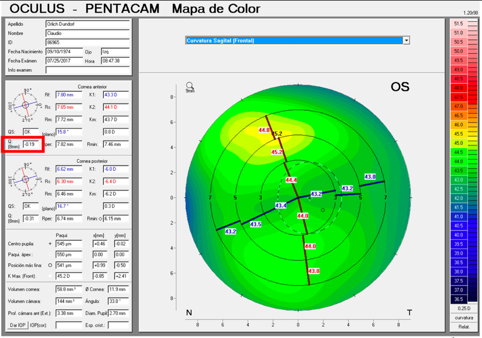
The alpha angle, unlike the kappa angle (best known for its importance in refractive surgery), is the distance between the center of the limbus and the visual axis. Under normal conditions an intraocular lens will be centered within the capsular bag, and the center of the bag will be very close to the center of the limbus. The alpha angle can be measured with the Pentacam (Oculus, Wetzlar, Germany) or iTrace (Tracey Technologies, Houston) (Figure 6).
A multi-element microscopy system can be aligned to provide Köhler (Koehler) illumination, in which the light collected from a light source like a lamp or light emitting diode (LED) is imaged differently than the light collected from the sample. The light source is intentionally never imaged to the sample (object) plane or to the camera sensor. The sample plane is instead uniformly illuminated, typically over the broad range of angles required for high-resolution imaging. As a result, Köhler illumination prevents superimposing an image of the lamp or LED structure onto the camera sensor.
Figure 3: Cones describe the light incident on a sample point from the condenser (left, gold), the light transmitted through the sample (right, yellow), and the range of light the objective can collect (right, orange). The cones' angles are measured from the optical axis. The angular ranges of the light cones incident on and transmitted by the sample are approximately the same (θcd ), since light that is not absorbed or scattered by the sample travels in an approximately straight line. The angular range (θobj ) accepted by the objective lens is can be different. The numerical apertures of the condenser (NAcd ) and objective (NAobj ) are often used to compare the angular ranges of the transmitted light to the light the objective lens can gather.
Dovetails are used for mechanical mating and optical port alignment of microscope components. Components are connected by inserting one dovetail into another, then tightening one or more locking setscrews on the female dovetail. Dovetails come in two shapes: linear and circular. Linear dovetails allow the mating components to slide before being locked down, providing flexible positioning options while limiting unneeded degrees of freedom. Circular dovetails align optical ports on different components, maintaining a single optical axis with minimal user intervention.
These achromatic air condensers are designed to be used with dry objectives. They are equipped with an adjustable aperture stop diaphragm that is controlled by a lever on the side, as shown in the below drawing.
For DIC imaging, Thorlabs offers N1 and N2 dry condenser prisms as well as N1 and N2 dry objectives. Note that an objective will have an N1 or N2 engraving to denote compatibility with a condenser prism.
This achromatic air condenser is designed to be used with dry objectives. It is equipped with an adjustable aperture stop diaphragm that is controlled by a lever on the side, as shown in the drawing below.
Trans-illumination illuminates from the opposite side of the sample as the viewing apparatus. Example imaging modalities include brightfield, differential interference contrast (DIC), Dodt gradient contrast, oblique, and darkfield microscopy. Trans-illumination modules, which condition light (on certain models) and direct it along the optical path, are attached to the support rail of the microscope body via a linear dovetail (see Microscope Dovetails tab or here). Please note that certain imaging modalities will require additional optics to alter the properties of the beam; these optics may be easily incorporated in the optical path via lens tubes and cage systems. In addition, Thorlabs offers condensers, which reshape input collimated light to help create optimal Köhler illumination. These attach to a mounting arm, which holds the condenser at the throat depth, or the distance from the optical path to the support rail. The arm attaches to a focusing module, used for aligning the condenser with respect to the sample and trans-illumination module.
Trans-illumination illuminates from the opposite side of the sample as the viewing apparatus. Example imaging modalities include brightfield, differential interference contrast (DIC), Dodt gradient contrast, oblique, and darkfield microscopy. Click here for additional information on trans-illumination with Cerna.
For sample viewing, Thorlabs offers trinoculars, double camera ports, and camera tubes. Light from the sample plane can be collected via cameras, photomultiplier tubes (PMTs), or custom setups using breadboard tops. Click here for additional information about viewing samples with a Cerna microscope.
The neutral lenses currently available on the market with prolate anterior and posterior surfaces are the Akreos, SofPort, L161 (Bausch +Lomb, Bridgewater, New Jersey), and the CT Asphina 409M (Carl Zeiss Meditec). These do not modify corneal spherical aberration, are less sensitive to tilt than aspherical lenses, and provide better image quality than spherical IOLs.
Alternately, the microscope can be configured so the objective both illuminates and collects light from the sample (Figure 2). In this case, there is no separate condenser lens system.
Thorlabs manufactures many components which use dovetails to mate with our own components or those of other manufacturers. To make it easier to identify dovetail compatibility, we have developed a set of dovetail designations. The naming convention of these designations is used only by Thorlabs and not other microscope manufacturers. The table to the right lists all the dovetails Thorlabs makes, along with their key dimensions.
Coma aberration
The CSA2001 adapter is used to mount a condenser with a male D3N dovetail to an optical assembly that uses Thorlabs' SM2 lens tubes. A 2 mm hex setscrew is included to secure the dovetail of the adapter to the condenser.
Using the Cerna microscope body, a sample can be illuminated in two directions: from above (epi-illumination, see yellow components to the right) or from below (trans-illumination, see orange components to the right).
Since an image of the source is at the front focal plane of the condenser lens, only bundles of parallel rays are incident on the sample plane. No source image is formed at the sample and the illumination is uniform.
Video 1: Optical elements in a transmission microscope, labeled on the left, are shown after they have been aligned to provide Köhler illumination. Under these conditions, as illustrated by the light rays traced through the illumination path in the animation, the sample plane is uniformly illuminated and images of the light source are not superimposed on the sample or camera sensor. In contrast, the light rays traced through the imaging path illustrate that the same optics do image the sample plane onto the camera sensor.
Chromatic aberration
The microscope body provides the foundation of any Cerna microscope. The 7.74" throat depth provides a large working space for experiments. Click here for additional information about the Cerna microscope body.
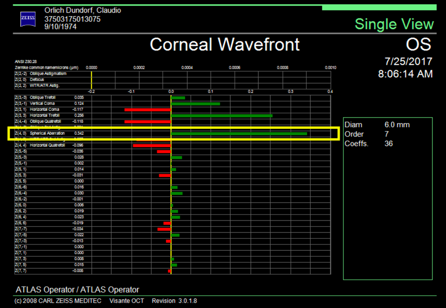
The average spherical aberration of the anterior cornea surface is slightly positive (between +0.27 and +0.30 μm), remaining stable throughout life.2 The natural crystalline compensates for this positive spherical aberration, inducing a negative spherical aberration of –0.20 μm, leaving a slightly positive total aberration of +0.10 μm. Spherical aberration of the lens changes over time unlike spherical aberration of the cornea, going from negative to positive as cataracts develop. This positive spherical aberration of the cataractous lens adds to the spherical positive aberration of the cornea, impairing the visual quality of patients. Based on this concept, intraocular lenses were developed with negative spherical aberration, which simulate a young lens that compensates for the average positive spherical aberration of the cornea. Some studies suggest that it is not necessary to correct spherical aberration completely, and in fact it is recommended to leave a slightly positive residual (+0.10 μm). A study performed on pilots of the American Air Force by Grimson et al. suggests that a quantity of positive spherical aberration can be correlated with visual acuities of 20/15 or better.3 It is impossible to completely correct the spherical aberration in all our patients as there is an interaction between much more complex aberrations than a sum of the existing spherical aberration and the intraocular lens induced aberration. Nevertheless, the objective must be directed to a final low spherical aberration, which allows the patient good contrast sensitivity.
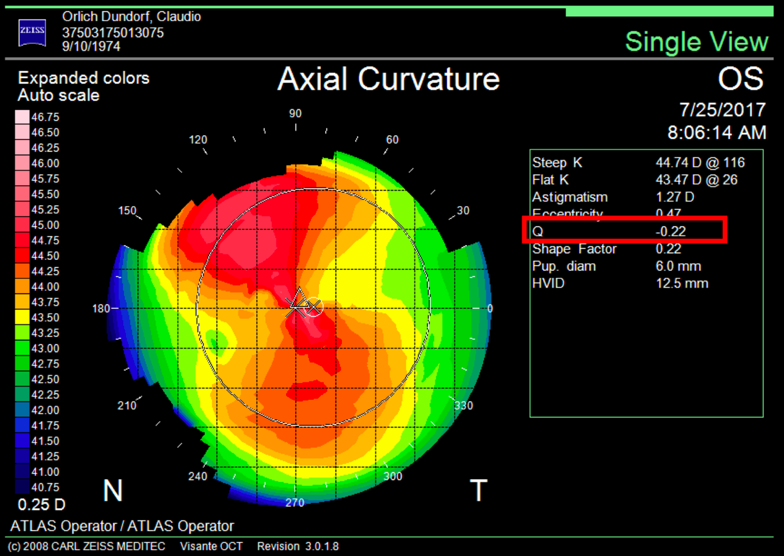
It is important to differentiate spherical aberration from corneal asphericity or commonly named with the Q coefficient. Both are related but different. Asphericity (Q) is a factor that tells us how much and how the cornea is peripherally flattened from the corneal apex, that is, if the cornea is prolate or oblate, while informing us of the degree of asphericity. A cornea with a Q of –0.20 is not the same as a cornea with a Q of –0.45; in both cases the cornea is prolate, but the prolaticity of the second case is greater, which means that the surface has a radius of peripheral curvature more flat than the first, and this means that it will have greater negative spherical aberration. A normal aspheric cornea has a Q factor between –0.20 and –0.45; a Q of zero would correspond to a completely spherical cornea, and a Q greater than zero corresponds to an oblate cornea, i.e., more powerful at the periphery than in the center, inducing positive spherical aberration. A hyperprolate cornea is considered to have a Q factor >0.6. Any corneal topographer nowadays will give us the Q value (Figure 2).
There are lenses with aspherical profiles that tolerate a greater lens offset, such as the CT LUCIA lens (Carl Zeiss Meditec). The “aspheric Zeiss optics” has a different design known as bi-sign,4 in which the IOL combines the advantages of neutral and correcting aspherical IOLs, making this lens a good choice for most patients and ideal for cases with an alpha angle greater than 0.5 mm or cases with the risk of the lens off center (Figure 5).
The word “aspheric” is used to describe a surface or in this case a lens that does not have a spherical shape. In an aspherical lens, the rays of light passing through the center do not focus at the same point as the rays passing through the periphery of the lens.
The CSC1001 and CSC1002 each contain an internal turret with four or seven slots, respectively, that is designed to mount DIC condenser prisms and illumination masks. This feature makes these condensers ideal for use in brightfield and oblique illumination, Dodt contrast, and DIC imaging. Please see the table to the left for the slots available in each turret. Each slot can be rotated into the beam path using a knurled dial on the side of the condenser. Labels are included that can be attached to the dial to indicate which slot is currently in the optical path. As shown in the photo below, the turret's slots can be accessed by removing the top cover using a 5/64" (2 mm) hex key.
This article was first published in ALACCSA-R #24, September/October 2017, pages 10–15, and is included here with permission from ALACCSA. For more information about ALACCSA, visit www.alaccsa.com.
Working Height: The height of the support rail of the microscope body plus the height of the base. The size of the working height, along with the throat depth, determine the working space available for microscopy.
This overview was developed to provide a general understanding of a Cerna® microscope. Click on the different portions of the microscope graphic to the right or use the links below to learn how a Cerna microscope visualizes a sample.
Source light transmitted through the sample plane is imaged to the objective back focal plane, which is located between the objective and tube lenses. No image of the light source is formed on the camera sensor, which preserves image quality.
Illumination Light PathThe illumination path begins with the light source and passes through the sample to the camera sensor. The video animation (Video 1, below) traces rays from an extended source, like a lamp or LED, through this light path.
The LCPN1 and LCPN5 adapters allow the user to attach a custom-built condenser or other light conditioning module to a Cerna, inverted Nikon Eclipse Ti, or upright Nikon Eclipse microscope. The adapters utilize the same male D3N dovetail as the above condensers; see the Microscope Dovetails tab for details. The LCPN1 adapter features internal SM30 (M30.5 x 0.5) threading for Ø30 mm lens tubes; two SM30RR retaining rings are included to secure an optic inside the adapter. The LCPN5 adapter features SM2 (2.035"-40) threading for SM2 lens tubes and includes one SM2RR retaining ring. Both adapters have four through holes with side-located locking setscrews (5/64" [2 mm] hex) that can be used to attach Ø6 mm cage rods for 60 mm cage systems. Additionally, the LCPN1 adapter features 4-40 tapped holes on 30 mm centers, located on the side opposite the dovetail, which can be used for 30 mm cage systems.
Various sample and equipment mounting options are available to take advantage of the large working space of this microscope system. Large samples and ancillary equipment can be mounted via mounting platforms, which fit around the microscope body and utilize a breadboard design with regularly spaced tapped through holes. Small samples can be mounted on rigid stands (for example, see the purple component to the right), which have holders for different methods of sample preparation and data collection, such as slides, well plates, and petri dishes. For more traditional sample mounting, slides can also be mounted directly onto the microscope body via a manual XY stage. The rigid stands can translate by way of motorized stages (sold separately), while the mounting platforms contain built-in mechanics for motorized or manual translation. Rigid stands can also be mounted on top of the mounting platforms for independent and synchronized movement of multiple instruments, if you are interested in performing experiments simultaneously during microscopy.
Note: Thorlabs does not guarantee compatibility with other industry-standard microscopes not explicitly mentioned on this webpage.
In order to reduce wear and simplify connections, dovetails are often machined with chamfers, recesses, and other mechanical features. Some examples of these variations are shown by the drawings below.
Field curvature
Image of the Light SourceAn image of the light source at the sample plane would not uniformly illuminate the sample (Figure 4, left, for example), since the light-emitting structures are clearly visible in images of the source. Köhler illumination instead uniformly illuminates the sample plane (Figure 4, right) by providing the light to the sample plane as bundles of parallel rays. In addition, aligning the system to provide Köhler illumination prevents the light source from being imaged at the camera sensor, which would superimpose an image of the light-emitting structures onto the image of the sample.
Some aspherical lenses have been designed with a prolate anterior surface (Tecnis, Johnson & Johnson Vision), a prolate posterior surface (AcrySof IQ, Alcon), or with both prolate surfaces (FineVision, PhysIOL, Liège, Belgium, and CT Asphina 509M). These give better contrast sensitivity when correcting positive spherical aberration of the cornea but generate less depth of focus than spherical lenses (Figure 4). In addition, they require a better centering, since a decentration of the optics of the lens induces other aberrations like coma. The performance of the lens depends on the pupil, and its function deteriorates in mesopic conditions.
The table below gives the dovetail, optical component threads, and cage system interfaces that are present on each DIY Cerna component. If a DIY Cerna component does not have one of the standard interfaces in the table, it is not listed here. Please note that mechanical compatibility does not ensure optical compatibility. Information on optical compatibility is available from Thorlabs' web presentations.
Various modules are available for sample viewing and data collection. Trinoculars have three points of vision to view the sample directly as well as with a camera. Double camera ports redirect or split the optical path among two viewing channels. Camera tubes increase or decrease the image magnification. For data collection, Thorlabs offers both cameras and photomultiplier tubes (PMTs), the latter being necessary to detect fluorescence signals for confocal microscopy. Breadboard tops provide functionality for custom-designed data collection setups. Modules are attached to the microscope body via a circular dovetail (see the Microscope Dovetails tab or here for details).
Throat Depth: The distance from the vertical portion of the optical path to the edge of the support rail of the microscope body. The size of the throat depth, along with the working height, determine the working space available for microscopy.
The CSC2001 works out-of-the-box with objectives ranging from 10X to 100X by adjusting the cone of illumination with the aperture diaphragm. For compatibility with 4X objective lenses, we offer the C4X lens, which is easily positioned within the CSC2001 using a CN1 tray (all items sold separately). For C4X specifications see the table below.
Large and small experiment mounting options are available to take advantage of the large working space of this microscope. Click here for additional information about mounting a sample for microscopy.
ResolutionThe resolution (δ ) of the microscope describes its ability to image two closely spaced points as a separable pair, instead of as a single point. A common equation,
The resolution of microscopy images is affected by several factors, including the numerical aperture (NA) of the condenser lens and the uniformity of the sample plane illumination. The NA of the condenser lens should be at least as large as the NA of the objective lens. Under these conditions, the condenser lens illuminates the sample over a range of angles that is at least as wide as the range of angles over which the objective lens collects light from the sample. In order to provide uniform illumination of the sample plane, a technique called Köhler illumination is often used. An important result of this illumination approach is that the source and sample are never imaged to the same plane. The following include more information about the relationship between the condenser and objective lenses, as well as Köhler illumination:
For customers interested in machining their own dovetails, the table to the right gives the outer diameter and angle (as defined by the drawings below) of each Thorlabs dovetail designation. However, the dovetail's height must be determined by the user, and for circular dovetails, the user must also determine the inner diameter and bore diameter. These quantities can vary for dovetails of the same type. One can use the intended mating part to verify compatibility.
Some colleagues have proposed selecting the intraocular lens platform depending on the corneal asphericity to correct; others prefer to leave a residual positive spherical aberration to give greater depth of focus to patients. In patients with multifocal lenses, with special corneal or previous refractive surgery, spherical aberration becomes more important. It is well known that multifocal lenses distribute the light in several foci, which contributes to losing between 8 and 20% of the transmitted. All these lenses present a loss of contrast at different distances; it is at this point that it is important to make use of all the resources that can improve contrast sensitivity to give greater visual quality to this group of patients. For the cataract surgeon, it is important to know the corneal asphericity of patients to offer them the best possible result.
Once illuminated, examining a sample with a microscope requires both focusing on the sample plane (see blue components to the right) and visualizing the resulting image (see pink components).
As an example, when the objective lens has a 0.7 NA with air (n = 1) between the lens and sample, the lens' angle of acceptance is θ = θobj = 44.43°. For the system illustrated in Figure 2, the NA of the illumination and the NA of the collected light are the same, since both light paths pass through the objective lens.
1. Oshika T, et al. Influence of pupil diameter on the relation between ocular higher-order aberration and contrast sensitivity after laser in situ keratomileusis. Invest Ophthalmol Vis Sci. 2006;47:1334–8.2. Guirao A. Optical aberrations of the human cornea as a function of age. J Opt Soc Am A Opt Image Sci Vis. 2000;17:1697–702.3. Grimson JM, et al. Contrast sensitivity: establishing normative data for use in screening prospective naval pilots. Aviat Space Environ Med. 2002;73:28–35.4. Portney V. New bi-sign aspheric IOL and its application. Optom Vis Sci. 2012;89:80–9.5. Piracha AR. Using angle alpha in premium IOL screening. Cataract & Refractive Surgery Today. 2016;(3):24–25.
Figure 1: In transmitted light microscopes, light from the light source is directed to the sample by the condenser optical system. The objective lens is used to collect the transmitted light. This collected light is then routed to create an image at a camera or eyepiece.
used to estimate this minimum separation includes only the wavelength () and the NA of the objective (NAobj ). While this equation seems to suggest the NA of the condenser (NAcd ) does not affect resolution, this is not the case. This equationactually assumes that NAcd ≥ NAobj .
Concave mirror
Bayonet Mount: A form of mechanical attachment with tabs on the male end that fit into L-shaped slots on the female end.
In the case of Thorlabs’ Cerna® microscopes, different dovetail types are used on different sections of the microscope to ensure that only compatible components can be mated. For example, our WFA2002 Epi-Illuminator Module has a male D1N dovetail that mates with the female D1N dovetail on the microscope body's epi-illumination arm, while the CSS2001 XY Microscopy Stage has a female D1Y dovetail that mates with the male D1Y dovetail on the CSA1051 Mounting Arm.
In the consultation, we will find that the corneal spherical aberration varies greatly among individuals, especially in the presence of pathological corneas or modified ones by post-refractive surgery. In a myopic treatment with excimer laser, a central flattening of the cornea is induced, generating an oblate cornea, more flat in the center than in the periphery, inducing a positive spherical aberration. In contrast, a hypermetropic correction increases the central curvature of the anterior surface of the cornea, generating a hyperprolate cornea, inducing greater negative spherical aberration that may contraindicate the use of an aspheric intraocular lens, which instead of correcting would worsen the existing spherical negative aberration, deteriorating the quality of vision.
The microscope body provides the foundation of any Cerna microscope. The support rail utilizes 95 mm rails machined to a high angular tolerance to ensure an aligned optical path and perpendicularity with the optical table. The support rail height chosen (350 - 600 mm) determines the vertical range available for experiments and microscopy components. The 7.74" throat depth, or distance from the optical path to the support rail, provides a large working space for experiments. Components attach to the body by way of either a linear dovetail on the support rail, or a circular dovetail on the epi-illumination arm (on certain models). Please see the Microscope Dovetails tab or here for further details.
Each of the multiple light-emitting points on the source radiate light over a range of angles. The collector lens gathers this light and transmits a beam whose maximum diameter is limited by the field stop. The light is then incident on the field lens, which forms an image of each source point at the aperture stop. The alignment of the source image at the aperture stop is critical, since the aperture stop is positioned at the front focal plane of the condenser lens.
Spherical aberration is included within the high order aberrations, specifically in the group of fourth order aberrations, along with quatrefoil and secondary astigmatism. Spherical aberration generally reduces retinal image contrast and affects visual quality, especially under mesopic conditions.1
Numerical ApertureThe condenser provides light to the sample plane over a range of different angles (Figure 3). A cone, drawn with its tip at a point on the sample and its base encircling the light from the condenser, can be used to quantify the range of incident angles (θcd ). The light transmitted by this point on the sample has approximately the same angular range. A different cone can be used to depict the angular range of light (θobj ) the objective lens is capable of gathering.
Although low order aberrations (myopia, hyperopia, and regular astigmatism) have a greater impact on vision, high order aberrations also play an important role, especially in patients who are candidates for multifocal lenses. Among the high order aberrations that can be corrected with cataract surgery is spherical aberration. There are multiple intraocular lens options that can correct this aberration, but when and how we should use them is a topic of debate and research in recent years.
Condenser Trays and TurretsEach condenser is equipped with either an internal turret (Item #'s CSC1001 and CSC1002) or a removable tray (Item # CSC2001) to allow for the addition of DIC condenser prisms or other optics. See below for details on the options available for each condenser.


 Ms.Cici
 8618319014500