
ND Filters – What Are They? What Do They Do? Do I Need ... - nd filters explained
Reticlerifle scope
The center frequency is determined just as before with the bandpass filter. The center frequency, fcenter= √ f1 f2 However, for narrowband filters, where the ratio of f2 to f1 is less than 1.1, the response shape approaches arithmetic symmetry and we can approximate the center frequency to be, fcenter= (f1 + f2)/2 The frequencies, f1 and f2 are the 2 cutoff -3dB frequencies. A high quality factor for a notch filter indicates the stopband is narrow. For example, let's assume that a notch filter circuit has a stopband from 2KHz to 3KHz. Using the formula, we get Q-factor of 2.5. Since the stopband is very narrow, the difference between f2 and f1 is small. Therefore, the denominator is relatively small, making for a large Q-factor. A low quality factor indicates the stopband is wide. For example, let's assume that a notch filter circuit has a stopband from 1KHz to 50KHz. Using the formula, we get a Q-factor of 0.144. Since the stopband is very wide, the difference between f2 and f1 is large. Therefore, the denominator is relatively large, making for a small Q-factor. So the quality factor again for a notch filter is the difference between the -3dB cutoff frequencies over the null frequency. It gives a good metric of how narrow or wide the stopband is for a given notch filter circuit design. Certain notch filter designs only allow for narrowband stopbands, or high Q-factors. Others allow for much wider stopbands, or low Q-factors. To use this calculator, a user simply enters the values of the 2 cutoff frequencies and specify whether the filter is a bandpass filter or a notch (bandstop) filter. The resultant q factor is then calculated and displayed. Related Resources Low Pass Filter Calculator High Pass Filter Calculator Bandpass Filter Calculator Notch Filter Calculator
The R3 features a floating centre dot and subtensions of 1 MOA marked by dots with a hash mark every 4 MOA. Heavy bars at 3, 6, 9 and 12 o’clock make target acquisition a breeze.
The frequencies, f1 and f2 are the 2 cutoff -3dB frequencies. A high quality factor for a notch filter indicates the stopband is narrow. For example, let's assume that a notch filter circuit has a stopband from 2KHz to 3KHz. Using the formula, we get Q-factor of 2.5. Since the stopband is very narrow, the difference between f2 and f1 is small. Therefore, the denominator is relatively small, making for a large Q-factor. A low quality factor indicates the stopband is wide. For example, let's assume that a notch filter circuit has a stopband from 1KHz to 50KHz. Using the formula, we get a Q-factor of 0.144. Since the stopband is very wide, the difference between f2 and f1 is large. Therefore, the denominator is relatively large, making for a small Q-factor. So the quality factor again for a notch filter is the difference between the -3dB cutoff frequencies over the null frequency. It gives a good metric of how narrow or wide the stopband is for a given notch filter circuit design. Certain notch filter designs only allow for narrowband stopbands, or high Q-factors. Others allow for much wider stopbands, or low Q-factors. To use this calculator, a user simply enters the values of the 2 cutoff frequencies and specify whether the filter is a bandpass filter or a notch (bandstop) filter. The resultant q factor is then calculated and displayed. Related Resources Low Pass Filter Calculator High Pass Filter Calculator Bandpass Filter Calculator Notch Filter Calculator
It’s the ideal choice for hunters and shooters looking for pinpoint precision as well as the ability to make high speed, snap shots on moving targets and game.
Join ZeroTech Optics for your chance to win a brand new Micro Red Dot every month. Experience the pinnacle of performance, innovation, and personal safety — right at your fingertips.
A traditional reticle, calibrated in mils, giving shooters the added ability to take long range shots with a high degree of precision.
The quality factor (Q-factor) calculator calculates the quality factor of either a bandpass filter circuit or a notch filter circuit. For a band pass filter, the quality factor is the ratio of the center frequency of the bandpass over the entire bandpass region from the lower to upper cutoff frequencies. Therefore, for a bandpass filter, the quality factor, Q= fcenter/ (f2 - f1). The frequencies, f11 and f2, are the 2 -3dB cutoff frequencies. F1 is the lower cutoff -3dB frequency and f2 is the upper -3dB cutoff frequency. The center frequency is the frequency in the center point of the bandpass. The center frequency, fcenter= √ f1 f2 However, for narrowband filters, where the ratio of f2 to f1 is less than 1.1, the response shape approaches arithmetic symmetry and we can approximate the center frequency to be, fcenter= (f1 + f2)/2 So these formulas above are how we can calculate the center frequency to find the Q-factor. A high quality factor indicates the bandpass is narrow. For example, let's assume that a bandpass filter circuit has a bandpass from 2KHz to 3KHz. Using the formula, we get Q-factor of 2.5. Since the bandpass filter is very narrow, the difference between f2 and f1 is small. Therefore, the denominator is relatively small, making for a large Q-factor. A low quality factor indicates the bandpass is wide. For example, let's assume that a bandpass filter circuit has a bandpass from 1KHz to 50KHz. Using the formula, we get a Q-factor of 0.144. Since the bandpass is very wide, the difference between f2 and f1 is large. Therefore, the denominator is relatively large, making for a small Q-factor. So Q-factor, again, is the ratio between the center frequency over the difference between the 2 -3dB cutoff frequencies. It gives a good metric of how narrow or wide the bandpass is for a given bandpass circuit design. Certain bandpass filter designs only allow for narrowband bandpasses, or high Q-factors. Others allow for much wider bandpasses, or low Q-factors. For a notch filter circuit, the quality factor is defined as the ratio of the entire stopband from f2 to f1 over the center frequency of the stopband, which is referred to as the null frequency or notch frequency. . So, for a notch filter, the quality factor is the entire stopband from the -3dB cutoff points over the null frequency, where the attenuation is the greatest. The quality factor shows how narrow or wide the stopband is for a notch filter. The quality factor of a notch filter is, Q= (f2 - f1)/fcenter. The center frequency is the center frequency of the stopband for a notch filter. It is the also referred to as the null frequency or the notch frequency. The center frequency is determined just as before with the bandpass filter. The center frequency, fcenter= √ f1 f2 However, for narrowband filters, where the ratio of f2 to f1 is less than 1.1, the response shape approaches arithmetic symmetry and we can approximate the center frequency to be, fcenter= (f1 + f2)/2 The frequencies, f1 and f2 are the 2 cutoff -3dB frequencies. A high quality factor for a notch filter indicates the stopband is narrow. For example, let's assume that a notch filter circuit has a stopband from 2KHz to 3KHz. Using the formula, we get Q-factor of 2.5. Since the stopband is very narrow, the difference between f2 and f1 is small. Therefore, the denominator is relatively small, making for a large Q-factor. A low quality factor indicates the stopband is wide. For example, let's assume that a notch filter circuit has a stopband from 1KHz to 50KHz. Using the formula, we get a Q-factor of 0.144. Since the stopband is very wide, the difference between f2 and f1 is large. Therefore, the denominator is relatively large, making for a small Q-factor. So the quality factor again for a notch filter is the difference between the -3dB cutoff frequencies over the null frequency. It gives a good metric of how narrow or wide the stopband is for a given notch filter circuit design. Certain notch filter designs only allow for narrowband stopbands, or high Q-factors. Others allow for much wider stopbands, or low Q-factors. To use this calculator, a user simply enters the values of the 2 cutoff frequencies and specify whether the filter is a bandpass filter or a notch (bandstop) filter. The resultant q factor is then calculated and displayed. Related Resources Low Pass Filter Calculator High Pass Filter Calculator Bandpass Filter Calculator Notch Filter Calculator
Subtended in 0.5 mil increments with integrated 0.1 mil measuring bars, the RMG allows shooters to apply elevation and windage holds without having to dial the turrets. A floating centre dot ensures a refined point of aim for zeroing and shooting groups, while the heavy bars with chevron ends at 3, 6, 9 and 12 o’clock help draw the shooter’s eye to the centre of the reticle at lower magnifications.
For a band pass filter, the quality factor is the ratio of the center frequency of the bandpass over the entire bandpass region from the lower to upper cutoff frequencies. Therefore, for a bandpass filter, the quality factor, Q= fcenter/ (f2 - f1). The frequencies, f11 and f2, are the 2 -3dB cutoff frequencies. F1 is the lower cutoff -3dB frequency and f2 is the upper -3dB cutoff frequency. The center frequency is the frequency in the center point of the bandpass. The center frequency, fcenter= √ f1 f2 However, for narrowband filters, where the ratio of f2 to f1 is less than 1.1, the response shape approaches arithmetic symmetry and we can approximate the center frequency to be, fcenter= (f1 + f2)/2 So these formulas above are how we can calculate the center frequency to find the Q-factor. A high quality factor indicates the bandpass is narrow. For example, let's assume that a bandpass filter circuit has a bandpass from 2KHz to 3KHz. Using the formula, we get Q-factor of 2.5. Since the bandpass filter is very narrow, the difference between f2 and f1 is small. Therefore, the denominator is relatively small, making for a large Q-factor. A low quality factor indicates the bandpass is wide. For example, let's assume that a bandpass filter circuit has a bandpass from 1KHz to 50KHz. Using the formula, we get a Q-factor of 0.144. Since the bandpass is very wide, the difference between f2 and f1 is large. Therefore, the denominator is relatively large, making for a small Q-factor. So Q-factor, again, is the ratio between the center frequency over the difference between the 2 -3dB cutoff frequencies. It gives a good metric of how narrow or wide the bandpass is for a given bandpass circuit design. Certain bandpass filter designs only allow for narrowband bandpasses, or high Q-factors. Others allow for much wider bandpasses, or low Q-factors. For a notch filter circuit, the quality factor is defined as the ratio of the entire stopband from f2 to f1 over the center frequency of the stopband, which is referred to as the null frequency or notch frequency. . So, for a notch filter, the quality factor is the entire stopband from the -3dB cutoff points over the null frequency, where the attenuation is the greatest. The quality factor shows how narrow or wide the stopband is for a notch filter. The quality factor of a notch filter is, Q= (f2 - f1)/fcenter. The center frequency is the center frequency of the stopband for a notch filter. It is the also referred to as the null frequency or the notch frequency. The center frequency is determined just as before with the bandpass filter. The center frequency, fcenter= √ f1 f2 However, for narrowband filters, where the ratio of f2 to f1 is less than 1.1, the response shape approaches arithmetic symmetry and we can approximate the center frequency to be, fcenter= (f1 + f2)/2 The frequencies, f1 and f2 are the 2 cutoff -3dB frequencies. A high quality factor for a notch filter indicates the stopband is narrow. For example, let's assume that a notch filter circuit has a stopband from 2KHz to 3KHz. Using the formula, we get Q-factor of 2.5. Since the stopband is very narrow, the difference between f2 and f1 is small. Therefore, the denominator is relatively small, making for a large Q-factor. A low quality factor indicates the stopband is wide. For example, let's assume that a notch filter circuit has a stopband from 1KHz to 50KHz. Using the formula, we get a Q-factor of 0.144. Since the stopband is very wide, the difference between f2 and f1 is large. Therefore, the denominator is relatively large, making for a small Q-factor. So the quality factor again for a notch filter is the difference between the -3dB cutoff frequencies over the null frequency. It gives a good metric of how narrow or wide the stopband is for a given notch filter circuit design. Certain notch filter designs only allow for narrowband stopbands, or high Q-factors. Others allow for much wider stopbands, or low Q-factors. To use this calculator, a user simply enters the values of the 2 cutoff frequencies and specify whether the filter is a bandpass filter or a notch (bandstop) filter. The resultant q factor is then calculated and displayed. Related Resources Low Pass Filter Calculator High Pass Filter Calculator Bandpass Filter Calculator Notch Filter Calculator
However, for narrowband filters, where the ratio of f2 to f1 is less than 1.1, the response shape approaches arithmetic symmetry and we can approximate the center frequency to be, fcenter= (f1 + f2)/2 So these formulas above are how we can calculate the center frequency to find the Q-factor. A high quality factor indicates the bandpass is narrow. For example, let's assume that a bandpass filter circuit has a bandpass from 2KHz to 3KHz. Using the formula, we get Q-factor of 2.5. Since the bandpass filter is very narrow, the difference between f2 and f1 is small. Therefore, the denominator is relatively small, making for a large Q-factor. A low quality factor indicates the bandpass is wide. For example, let's assume that a bandpass filter circuit has a bandpass from 1KHz to 50KHz. Using the formula, we get a Q-factor of 0.144. Since the bandpass is very wide, the difference between f2 and f1 is large. Therefore, the denominator is relatively large, making for a small Q-factor. So Q-factor, again, is the ratio between the center frequency over the difference between the 2 -3dB cutoff frequencies. It gives a good metric of how narrow or wide the bandpass is for a given bandpass circuit design. Certain bandpass filter designs only allow for narrowband bandpasses, or high Q-factors. Others allow for much wider bandpasses, or low Q-factors. For a notch filter circuit, the quality factor is defined as the ratio of the entire stopband from f2 to f1 over the center frequency of the stopband, which is referred to as the null frequency or notch frequency. . So, for a notch filter, the quality factor is the entire stopband from the -3dB cutoff points over the null frequency, where the attenuation is the greatest. The quality factor shows how narrow or wide the stopband is for a notch filter. The quality factor of a notch filter is, Q= (f2 - f1)/fcenter. The center frequency is the center frequency of the stopband for a notch filter. It is the also referred to as the null frequency or the notch frequency. The center frequency is determined just as before with the bandpass filter. The center frequency, fcenter= √ f1 f2 However, for narrowband filters, where the ratio of f2 to f1 is less than 1.1, the response shape approaches arithmetic symmetry and we can approximate the center frequency to be, fcenter= (f1 + f2)/2 The frequencies, f1 and f2 are the 2 cutoff -3dB frequencies. A high quality factor for a notch filter indicates the stopband is narrow. For example, let's assume that a notch filter circuit has a stopband from 2KHz to 3KHz. Using the formula, we get Q-factor of 2.5. Since the stopband is very narrow, the difference between f2 and f1 is small. Therefore, the denominator is relatively small, making for a large Q-factor. A low quality factor indicates the stopband is wide. For example, let's assume that a notch filter circuit has a stopband from 1KHz to 50KHz. Using the formula, we get a Q-factor of 0.144. Since the stopband is very wide, the difference between f2 and f1 is large. Therefore, the denominator is relatively large, making for a small Q-factor. So the quality factor again for a notch filter is the difference between the -3dB cutoff frequencies over the null frequency. It gives a good metric of how narrow or wide the stopband is for a given notch filter circuit design. Certain notch filter designs only allow for narrowband stopbands, or high Q-factors. Others allow for much wider stopbands, or low Q-factors. To use this calculator, a user simply enters the values of the 2 cutoff frequencies and specify whether the filter is a bandpass filter or a notch (bandstop) filter. The resultant q factor is then calculated and displayed. Related Resources Low Pass Filter Calculator High Pass Filter Calculator Bandpass Filter Calculator Notch Filter Calculator
Unobtrusive elevation holds are available at 2.5, 5, 10, 15, 20 and 25 MOA, allowing the shooter to maximise the potential of their rifle and ammunition combination.
So Q-factor, again, is the ratio between the center frequency over the difference between the 2 -3dB cutoff frequencies. It gives a good metric of how narrow or wide the bandpass is for a given bandpass circuit design. Certain bandpass filter designs only allow for narrowband bandpasses, or high Q-factors. Others allow for much wider bandpasses, or low Q-factors. For a notch filter circuit, the quality factor is defined as the ratio of the entire stopband from f2 to f1 over the center frequency of the stopband, which is referred to as the null frequency or notch frequency. . So, for a notch filter, the quality factor is the entire stopband from the -3dB cutoff points over the null frequency, where the attenuation is the greatest. The quality factor shows how narrow or wide the stopband is for a notch filter. The quality factor of a notch filter is, Q= (f2 - f1)/fcenter. The center frequency is the center frequency of the stopband for a notch filter. It is the also referred to as the null frequency or the notch frequency. The center frequency is determined just as before with the bandpass filter. The center frequency, fcenter= √ f1 f2 However, for narrowband filters, where the ratio of f2 to f1 is less than 1.1, the response shape approaches arithmetic symmetry and we can approximate the center frequency to be, fcenter= (f1 + f2)/2 The frequencies, f1 and f2 are the 2 cutoff -3dB frequencies. A high quality factor for a notch filter indicates the stopband is narrow. For example, let's assume that a notch filter circuit has a stopband from 2KHz to 3KHz. Using the formula, we get Q-factor of 2.5. Since the stopband is very narrow, the difference between f2 and f1 is small. Therefore, the denominator is relatively small, making for a large Q-factor. A low quality factor indicates the stopband is wide. For example, let's assume that a notch filter circuit has a stopband from 1KHz to 50KHz. Using the formula, we get a Q-factor of 0.144. Since the stopband is very wide, the difference between f2 and f1 is large. Therefore, the denominator is relatively large, making for a small Q-factor. So the quality factor again for a notch filter is the difference between the -3dB cutoff frequencies over the null frequency. It gives a good metric of how narrow or wide the stopband is for a given notch filter circuit design. Certain notch filter designs only allow for narrowband stopbands, or high Q-factors. Others allow for much wider stopbands, or low Q-factors. To use this calculator, a user simply enters the values of the 2 cutoff frequencies and specify whether the filter is a bandpass filter or a notch (bandstop) filter. The resultant q factor is then calculated and displayed. Related Resources Low Pass Filter Calculator High Pass Filter Calculator Bandpass Filter Calculator Notch Filter Calculator
A low quality factor indicates the stopband is wide. For example, let's assume that a notch filter circuit has a stopband from 1KHz to 50KHz. Using the formula, we get a Q-factor of 0.144. Since the stopband is very wide, the difference between f2 and f1 is large. Therefore, the denominator is relatively large, making for a small Q-factor. So the quality factor again for a notch filter is the difference between the -3dB cutoff frequencies over the null frequency. It gives a good metric of how narrow or wide the stopband is for a given notch filter circuit design. Certain notch filter designs only allow for narrowband stopbands, or high Q-factors. Others allow for much wider stopbands, or low Q-factors. To use this calculator, a user simply enters the values of the 2 cutoff frequencies and specify whether the filter is a bandpass filter or a notch (bandstop) filter. The resultant q factor is then calculated and displayed. Related Resources Low Pass Filter Calculator High Pass Filter Calculator Bandpass Filter Calculator Notch Filter Calculator
Reticlevs crosshair
RAR Illuminated reticle allows for rapid target acquisition and speed shooting, yet enables precision shots when required. The heavy outer bars taper to sharp and precise points, leading the shooters eye naturally to the centre of the reticle. Incorporation of a segmented ¾ illuminated circle and centre dot make speed shooting a breeze. Integrated 2 MOA hash marks and numbered 4 MOA elevation intervals give shooters the ability to account for wind and bullet drop.
Reticlein games
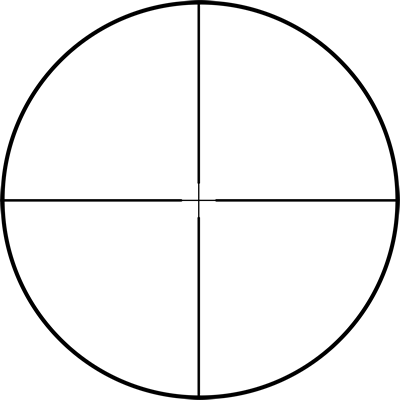
A floating centre cross allows for a refined point of aim whilst losing none of the ‘pointability’ of a traditional hunting reticle.
The center frequency is the frequency in the center point of the bandpass. The center frequency, fcenter= √ f1 f2 However, for narrowband filters, where the ratio of f2 to f1 is less than 1.1, the response shape approaches arithmetic symmetry and we can approximate the center frequency to be, fcenter= (f1 + f2)/2 So these formulas above are how we can calculate the center frequency to find the Q-factor. A high quality factor indicates the bandpass is narrow. For example, let's assume that a bandpass filter circuit has a bandpass from 2KHz to 3KHz. Using the formula, we get Q-factor of 2.5. Since the bandpass filter is very narrow, the difference between f2 and f1 is small. Therefore, the denominator is relatively small, making for a large Q-factor. A low quality factor indicates the bandpass is wide. For example, let's assume that a bandpass filter circuit has a bandpass from 1KHz to 50KHz. Using the formula, we get a Q-factor of 0.144. Since the bandpass is very wide, the difference between f2 and f1 is large. Therefore, the denominator is relatively large, making for a small Q-factor. So Q-factor, again, is the ratio between the center frequency over the difference between the 2 -3dB cutoff frequencies. It gives a good metric of how narrow or wide the bandpass is for a given bandpass circuit design. Certain bandpass filter designs only allow for narrowband bandpasses, or high Q-factors. Others allow for much wider bandpasses, or low Q-factors. For a notch filter circuit, the quality factor is defined as the ratio of the entire stopband from f2 to f1 over the center frequency of the stopband, which is referred to as the null frequency or notch frequency. . So, for a notch filter, the quality factor is the entire stopband from the -3dB cutoff points over the null frequency, where the attenuation is the greatest. The quality factor shows how narrow or wide the stopband is for a notch filter. The quality factor of a notch filter is, Q= (f2 - f1)/fcenter. The center frequency is the center frequency of the stopband for a notch filter. It is the also referred to as the null frequency or the notch frequency. The center frequency is determined just as before with the bandpass filter. The center frequency, fcenter= √ f1 f2 However, for narrowband filters, where the ratio of f2 to f1 is less than 1.1, the response shape approaches arithmetic symmetry and we can approximate the center frequency to be, fcenter= (f1 + f2)/2 The frequencies, f1 and f2 are the 2 cutoff -3dB frequencies. A high quality factor for a notch filter indicates the stopband is narrow. For example, let's assume that a notch filter circuit has a stopband from 2KHz to 3KHz. Using the formula, we get Q-factor of 2.5. Since the stopband is very narrow, the difference between f2 and f1 is small. Therefore, the denominator is relatively small, making for a large Q-factor. A low quality factor indicates the stopband is wide. For example, let's assume that a notch filter circuit has a stopband from 1KHz to 50KHz. Using the formula, we get a Q-factor of 0.144. Since the stopband is very wide, the difference between f2 and f1 is large. Therefore, the denominator is relatively large, making for a small Q-factor. So the quality factor again for a notch filter is the difference between the -3dB cutoff frequencies over the null frequency. It gives a good metric of how narrow or wide the stopband is for a given notch filter circuit design. Certain notch filter designs only allow for narrowband stopbands, or high Q-factors. Others allow for much wider stopbands, or low Q-factors. To use this calculator, a user simply enters the values of the 2 cutoff frequencies and specify whether the filter is a bandpass filter or a notch (bandstop) filter. The resultant q factor is then calculated and displayed. Related Resources Low Pass Filter Calculator High Pass Filter Calculator Bandpass Filter Calculator Notch Filter Calculator
Reticlemeaning
The quality factor of a notch filter is, Q= (f2 - f1)/fcenter. The center frequency is the center frequency of the stopband for a notch filter. It is the also referred to as the null frequency or the notch frequency. The center frequency is determined just as before with the bandpass filter. The center frequency, fcenter= √ f1 f2 However, for narrowband filters, where the ratio of f2 to f1 is less than 1.1, the response shape approaches arithmetic symmetry and we can approximate the center frequency to be, fcenter= (f1 + f2)/2 The frequencies, f1 and f2 are the 2 cutoff -3dB frequencies. A high quality factor for a notch filter indicates the stopband is narrow. For example, let's assume that a notch filter circuit has a stopband from 2KHz to 3KHz. Using the formula, we get Q-factor of 2.5. Since the stopband is very narrow, the difference between f2 and f1 is small. Therefore, the denominator is relatively small, making for a large Q-factor. A low quality factor indicates the stopband is wide. For example, let's assume that a notch filter circuit has a stopband from 1KHz to 50KHz. Using the formula, we get a Q-factor of 0.144. Since the stopband is very wide, the difference between f2 and f1 is large. Therefore, the denominator is relatively large, making for a small Q-factor. So the quality factor again for a notch filter is the difference between the -3dB cutoff frequencies over the null frequency. It gives a good metric of how narrow or wide the stopband is for a given notch filter circuit design. Certain notch filter designs only allow for narrowband stopbands, or high Q-factors. Others allow for much wider stopbands, or low Q-factors. To use this calculator, a user simply enters the values of the 2 cutoff frequencies and specify whether the filter is a bandpass filter or a notch (bandstop) filter. The resultant q factor is then calculated and displayed. Related Resources Low Pass Filter Calculator High Pass Filter Calculator Bandpass Filter Calculator Notch Filter Calculator
So, for a notch filter, the quality factor is the entire stopband from the -3dB cutoff points over the null frequency, where the attenuation is the greatest. The quality factor shows how narrow or wide the stopband is for a notch filter. The quality factor of a notch filter is, Q= (f2 - f1)/fcenter. The center frequency is the center frequency of the stopband for a notch filter. It is the also referred to as the null frequency or the notch frequency. The center frequency is determined just as before with the bandpass filter. The center frequency, fcenter= √ f1 f2 However, for narrowband filters, where the ratio of f2 to f1 is less than 1.1, the response shape approaches arithmetic symmetry and we can approximate the center frequency to be, fcenter= (f1 + f2)/2 The frequencies, f1 and f2 are the 2 cutoff -3dB frequencies. A high quality factor for a notch filter indicates the stopband is narrow. For example, let's assume that a notch filter circuit has a stopband from 2KHz to 3KHz. Using the formula, we get Q-factor of 2.5. Since the stopband is very narrow, the difference between f2 and f1 is small. Therefore, the denominator is relatively small, making for a large Q-factor. A low quality factor indicates the stopband is wide. For example, let's assume that a notch filter circuit has a stopband from 1KHz to 50KHz. Using the formula, we get a Q-factor of 0.144. Since the stopband is very wide, the difference between f2 and f1 is large. Therefore, the denominator is relatively large, making for a small Q-factor. So the quality factor again for a notch filter is the difference between the -3dB cutoff frequencies over the null frequency. It gives a good metric of how narrow or wide the stopband is for a given notch filter circuit design. Certain notch filter designs only allow for narrowband stopbands, or high Q-factors. Others allow for much wider stopbands, or low Q-factors. To use this calculator, a user simply enters the values of the 2 cutoff frequencies and specify whether the filter is a bandpass filter or a notch (bandstop) filter. The resultant q factor is then calculated and displayed. Related Resources Low Pass Filter Calculator High Pass Filter Calculator Bandpass Filter Calculator Notch Filter Calculator
The center frequency is the center frequency of the stopband for a notch filter. It is the also referred to as the null frequency or the notch frequency. The center frequency is determined just as before with the bandpass filter. The center frequency, fcenter= √ f1 f2 However, for narrowband filters, where the ratio of f2 to f1 is less than 1.1, the response shape approaches arithmetic symmetry and we can approximate the center frequency to be, fcenter= (f1 + f2)/2 The frequencies, f1 and f2 are the 2 cutoff -3dB frequencies. A high quality factor for a notch filter indicates the stopband is narrow. For example, let's assume that a notch filter circuit has a stopband from 2KHz to 3KHz. Using the formula, we get Q-factor of 2.5. Since the stopband is very narrow, the difference between f2 and f1 is small. Therefore, the denominator is relatively small, making for a large Q-factor. A low quality factor indicates the stopband is wide. For example, let's assume that a notch filter circuit has a stopband from 1KHz to 50KHz. Using the formula, we get a Q-factor of 0.144. Since the stopband is very wide, the difference between f2 and f1 is large. Therefore, the denominator is relatively large, making for a small Q-factor. So the quality factor again for a notch filter is the difference between the -3dB cutoff frequencies over the null frequency. It gives a good metric of how narrow or wide the stopband is for a given notch filter circuit design. Certain notch filter designs only allow for narrowband stopbands, or high Q-factors. Others allow for much wider stopbands, or low Q-factors. To use this calculator, a user simply enters the values of the 2 cutoff frequencies and specify whether the filter is a bandpass filter or a notch (bandstop) filter. The resultant q factor is then calculated and displayed. Related Resources Low Pass Filter Calculator High Pass Filter Calculator Bandpass Filter Calculator Notch Filter Calculator
The center frequency, fcenter= √ f1 f2 However, for narrowband filters, where the ratio of f2 to f1 is less than 1.1, the response shape approaches arithmetic symmetry and we can approximate the center frequency to be, fcenter= (f1 + f2)/2 The frequencies, f1 and f2 are the 2 cutoff -3dB frequencies. A high quality factor for a notch filter indicates the stopband is narrow. For example, let's assume that a notch filter circuit has a stopband from 2KHz to 3KHz. Using the formula, we get Q-factor of 2.5. Since the stopband is very narrow, the difference between f2 and f1 is small. Therefore, the denominator is relatively small, making for a large Q-factor. A low quality factor indicates the stopband is wide. For example, let's assume that a notch filter circuit has a stopband from 1KHz to 50KHz. Using the formula, we get a Q-factor of 0.144. Since the stopband is very wide, the difference between f2 and f1 is large. Therefore, the denominator is relatively large, making for a small Q-factor. So the quality factor again for a notch filter is the difference between the -3dB cutoff frequencies over the null frequency. It gives a good metric of how narrow or wide the stopband is for a given notch filter circuit design. Certain notch filter designs only allow for narrowband stopbands, or high Q-factors. Others allow for much wider stopbands, or low Q-factors. To use this calculator, a user simply enters the values of the 2 cutoff frequencies and specify whether the filter is a bandpass filter or a notch (bandstop) filter. The resultant q factor is then calculated and displayed. Related Resources Low Pass Filter Calculator High Pass Filter Calculator Bandpass Filter Calculator Notch Filter Calculator
Whether holding elevation and windage for high speed, precision shots or dialling your turrets for long range targets, the RMG (Refined Mil Grid) is the perfect blend of precision and speed.
To use this calculator, a user simply enters the values of the 2 cutoff frequencies and specify whether the filter is a bandpass filter or a notch (bandstop) filter. The resultant q factor is then calculated and displayed. Related Resources Low Pass Filter Calculator High Pass Filter Calculator Bandpass Filter Calculator Notch Filter Calculator
To provide the best experiences, we utilize technologies such as cookies to store and access device information. Consenting to these technologies enables us to process data like browsing behavior or unique IDs on this site. Not consenting or withdrawing consent may adversely affect certain features and functions.
The PHR II shares all the features of the PHR reticle with the addition of a floating center dot for an ultra-refined point of aim as well as a finer 6 o’clock post, enabling even more precise elevation ‘hold overs’.
Subtended in 2 MOA increments with integrated ½ MOA measuring bars, the RMG MOA allows shooters to apply elevation and windage holds without having to dial the turrets. A floating centre dot ensures a refined point of aim for zeroing and shooting groups, while the heavy bars with chevron ends at 3, 6, 9 and 12 o’clock help draw the shooter’s eye to the centre of the reticle at lower magnifications.
The R3 reticle allows the shooter to enjoy all aspects of a second focal plane (SFP) scope without losing the ability to ‘hold over’ with extreme precision for long range shots.
Reticlein semiconductor
The PHR II shares all the features of the PHR reticle with the addition of a floating centre dot for an ultra-refined point of aim as well as a finer 6 o’clock post, enabling even more precise elevation ‘hold overs’.
Reticlescope
So the quality factor again for a notch filter is the difference between the -3dB cutoff frequencies over the null frequency. It gives a good metric of how narrow or wide the stopband is for a given notch filter circuit design. Certain notch filter designs only allow for narrowband stopbands, or high Q-factors. Others allow for much wider stopbands, or low Q-factors. To use this calculator, a user simply enters the values of the 2 cutoff frequencies and specify whether the filter is a bandpass filter or a notch (bandstop) filter. The resultant q factor is then calculated and displayed. Related Resources Low Pass Filter Calculator High Pass Filter Calculator Bandpass Filter Calculator Notch Filter Calculator
Precision – Simplicity – Speed. The LR Hunter has been developed for shooters and hunters who are looking for a ‘do it all’ reticle. The combination of First Focal Plane (FFP) and adjustable illumination enables the LR Hunter to mimic traditional reticles on low magnification. Whilst at higher powers, a level of precision is on offer to help you connect with the farthest targets. The LR Hunter is a true hybrid.
Reticlepronunciation
Unobtrusive elevation holds are available at 1.1, 2.5, 5, 10, 15, 20 and 25 MOA, allowing the shooter to maximize the potential of their rifle and ammunition combination.
Reticleor reticule

A high quality factor for a notch filter indicates the stopband is narrow. For example, let's assume that a notch filter circuit has a stopband from 2KHz to 3KHz. Using the formula, we get Q-factor of 2.5. Since the stopband is very narrow, the difference between f2 and f1 is small. Therefore, the denominator is relatively small, making for a large Q-factor. A low quality factor indicates the stopband is wide. For example, let's assume that a notch filter circuit has a stopband from 1KHz to 50KHz. Using the formula, we get a Q-factor of 0.144. Since the stopband is very wide, the difference between f2 and f1 is large. Therefore, the denominator is relatively large, making for a small Q-factor. So the quality factor again for a notch filter is the difference between the -3dB cutoff frequencies over the null frequency. It gives a good metric of how narrow or wide the stopband is for a given notch filter circuit design. Certain notch filter designs only allow for narrowband stopbands, or high Q-factors. Others allow for much wider stopbands, or low Q-factors. To use this calculator, a user simply enters the values of the 2 cutoff frequencies and specify whether the filter is a bandpass filter or a notch (bandstop) filter. The resultant q factor is then calculated and displayed. Related Resources Low Pass Filter Calculator High Pass Filter Calculator Bandpass Filter Calculator Notch Filter Calculator
The OSR enables the largest possible field of view due to its offset design whilst retaining all the benefits of a FFP reticle. When precision and speed matter, the OSR is the perfect companion.
The frequencies, f11 and f2, are the 2 -3dB cutoff frequencies. F1 is the lower cutoff -3dB frequency and f2 is the upper -3dB cutoff frequency. The center frequency is the frequency in the center point of the bandpass. The center frequency, fcenter= √ f1 f2 However, for narrowband filters, where the ratio of f2 to f1 is less than 1.1, the response shape approaches arithmetic symmetry and we can approximate the center frequency to be, fcenter= (f1 + f2)/2 So these formulas above are how we can calculate the center frequency to find the Q-factor. A high quality factor indicates the bandpass is narrow. For example, let's assume that a bandpass filter circuit has a bandpass from 2KHz to 3KHz. Using the formula, we get Q-factor of 2.5. Since the bandpass filter is very narrow, the difference between f2 and f1 is small. Therefore, the denominator is relatively small, making for a large Q-factor. A low quality factor indicates the bandpass is wide. For example, let's assume that a bandpass filter circuit has a bandpass from 1KHz to 50KHz. Using the formula, we get a Q-factor of 0.144. Since the bandpass is very wide, the difference between f2 and f1 is large. Therefore, the denominator is relatively large, making for a small Q-factor. So Q-factor, again, is the ratio between the center frequency over the difference between the 2 -3dB cutoff frequencies. It gives a good metric of how narrow or wide the bandpass is for a given bandpass circuit design. Certain bandpass filter designs only allow for narrowband bandpasses, or high Q-factors. Others allow for much wider bandpasses, or low Q-factors. For a notch filter circuit, the quality factor is defined as the ratio of the entire stopband from f2 to f1 over the center frequency of the stopband, which is referred to as the null frequency or notch frequency. . So, for a notch filter, the quality factor is the entire stopband from the -3dB cutoff points over the null frequency, where the attenuation is the greatest. The quality factor shows how narrow or wide the stopband is for a notch filter. The quality factor of a notch filter is, Q= (f2 - f1)/fcenter. The center frequency is the center frequency of the stopband for a notch filter. It is the also referred to as the null frequency or the notch frequency. The center frequency is determined just as before with the bandpass filter. The center frequency, fcenter= √ f1 f2 However, for narrowband filters, where the ratio of f2 to f1 is less than 1.1, the response shape approaches arithmetic symmetry and we can approximate the center frequency to be, fcenter= (f1 + f2)/2 The frequencies, f1 and f2 are the 2 cutoff -3dB frequencies. A high quality factor for a notch filter indicates the stopband is narrow. For example, let's assume that a notch filter circuit has a stopband from 2KHz to 3KHz. Using the formula, we get Q-factor of 2.5. Since the stopband is very narrow, the difference between f2 and f1 is small. Therefore, the denominator is relatively small, making for a large Q-factor. A low quality factor indicates the stopband is wide. For example, let's assume that a notch filter circuit has a stopband from 1KHz to 50KHz. Using the formula, we get a Q-factor of 0.144. Since the stopband is very wide, the difference between f2 and f1 is large. Therefore, the denominator is relatively large, making for a small Q-factor. So the quality factor again for a notch filter is the difference between the -3dB cutoff frequencies over the null frequency. It gives a good metric of how narrow or wide the stopband is for a given notch filter circuit design. Certain notch filter designs only allow for narrowband stopbands, or high Q-factors. Others allow for much wider stopbands, or low Q-factors. To use this calculator, a user simply enters the values of the 2 cutoff frequencies and specify whether the filter is a bandpass filter or a notch (bandstop) filter. The resultant q factor is then calculated and displayed. Related Resources Low Pass Filter Calculator High Pass Filter Calculator Bandpass Filter Calculator Notch Filter Calculator
A low quality factor indicates the bandpass is wide. For example, let's assume that a bandpass filter circuit has a bandpass from 1KHz to 50KHz. Using the formula, we get a Q-factor of 0.144. Since the bandpass is very wide, the difference between f2 and f1 is large. Therefore, the denominator is relatively large, making for a small Q-factor. So Q-factor, again, is the ratio between the center frequency over the difference between the 2 -3dB cutoff frequencies. It gives a good metric of how narrow or wide the bandpass is for a given bandpass circuit design. Certain bandpass filter designs only allow for narrowband bandpasses, or high Q-factors. Others allow for much wider bandpasses, or low Q-factors. For a notch filter circuit, the quality factor is defined as the ratio of the entire stopband from f2 to f1 over the center frequency of the stopband, which is referred to as the null frequency or notch frequency. . So, for a notch filter, the quality factor is the entire stopband from the -3dB cutoff points over the null frequency, where the attenuation is the greatest. The quality factor shows how narrow or wide the stopband is for a notch filter. The quality factor of a notch filter is, Q= (f2 - f1)/fcenter. The center frequency is the center frequency of the stopband for a notch filter. It is the also referred to as the null frequency or the notch frequency. The center frequency is determined just as before with the bandpass filter. The center frequency, fcenter= √ f1 f2 However, for narrowband filters, where the ratio of f2 to f1 is less than 1.1, the response shape approaches arithmetic symmetry and we can approximate the center frequency to be, fcenter= (f1 + f2)/2 The frequencies, f1 and f2 are the 2 cutoff -3dB frequencies. A high quality factor for a notch filter indicates the stopband is narrow. For example, let's assume that a notch filter circuit has a stopband from 2KHz to 3KHz. Using the formula, we get Q-factor of 2.5. Since the stopband is very narrow, the difference between f2 and f1 is small. Therefore, the denominator is relatively small, making for a large Q-factor. A low quality factor indicates the stopband is wide. For example, let's assume that a notch filter circuit has a stopband from 1KHz to 50KHz. Using the formula, we get a Q-factor of 0.144. Since the stopband is very wide, the difference between f2 and f1 is large. Therefore, the denominator is relatively large, making for a small Q-factor. So the quality factor again for a notch filter is the difference between the -3dB cutoff frequencies over the null frequency. It gives a good metric of how narrow or wide the stopband is for a given notch filter circuit design. Certain notch filter designs only allow for narrowband stopbands, or high Q-factors. Others allow for much wider stopbands, or low Q-factors. To use this calculator, a user simply enters the values of the 2 cutoff frequencies and specify whether the filter is a bandpass filter or a notch (bandstop) filter. The resultant q factor is then calculated and displayed. Related Resources Low Pass Filter Calculator High Pass Filter Calculator Bandpass Filter Calculator Notch Filter Calculator
Whether holding elevation and windage for high speed, precision shots or dialling your turrets for long range targets, the RMG 2 is the perfect blend of precision and speed, now with extended windage and elevation.Subtended in 0.5 mil increments with integrated 0.1 mil measuring bars, the RMG 2 allows shooters to apply elevation and windage holds without having to dial the turrets. A floating centre dot ensures a refined point of aim for zeroing and shooting groups, while the heavy bars with chevron ends at 3, 6, 9 and 12 o’clock help draw the shooter’s eye to the centre of the reticle at lower magnifications.The illumination feature has been carefully designed to allow maximum usability of the reticle in all environmental conditions, whilst permitting effective shot placement at shorter ranges on lower magnification settings.
So these formulas above are how we can calculate the center frequency to find the Q-factor. A high quality factor indicates the bandpass is narrow. For example, let's assume that a bandpass filter circuit has a bandpass from 2KHz to 3KHz. Using the formula, we get Q-factor of 2.5. Since the bandpass filter is very narrow, the difference between f2 and f1 is small. Therefore, the denominator is relatively small, making for a large Q-factor. A low quality factor indicates the bandpass is wide. For example, let's assume that a bandpass filter circuit has a bandpass from 1KHz to 50KHz. Using the formula, we get a Q-factor of 0.144. Since the bandpass is very wide, the difference between f2 and f1 is large. Therefore, the denominator is relatively large, making for a small Q-factor. So Q-factor, again, is the ratio between the center frequency over the difference between the 2 -3dB cutoff frequencies. It gives a good metric of how narrow or wide the bandpass is for a given bandpass circuit design. Certain bandpass filter designs only allow for narrowband bandpasses, or high Q-factors. Others allow for much wider bandpasses, or low Q-factors. For a notch filter circuit, the quality factor is defined as the ratio of the entire stopband from f2 to f1 over the center frequency of the stopband, which is referred to as the null frequency or notch frequency. . So, for a notch filter, the quality factor is the entire stopband from the -3dB cutoff points over the null frequency, where the attenuation is the greatest. The quality factor shows how narrow or wide the stopband is for a notch filter. The quality factor of a notch filter is, Q= (f2 - f1)/fcenter. The center frequency is the center frequency of the stopband for a notch filter. It is the also referred to as the null frequency or the notch frequency. The center frequency is determined just as before with the bandpass filter. The center frequency, fcenter= √ f1 f2 However, for narrowband filters, where the ratio of f2 to f1 is less than 1.1, the response shape approaches arithmetic symmetry and we can approximate the center frequency to be, fcenter= (f1 + f2)/2 The frequencies, f1 and f2 are the 2 cutoff -3dB frequencies. A high quality factor for a notch filter indicates the stopband is narrow. For example, let's assume that a notch filter circuit has a stopband from 2KHz to 3KHz. Using the formula, we get Q-factor of 2.5. Since the stopband is very narrow, the difference between f2 and f1 is small. Therefore, the denominator is relatively small, making for a large Q-factor. A low quality factor indicates the stopband is wide. For example, let's assume that a notch filter circuit has a stopband from 1KHz to 50KHz. Using the formula, we get a Q-factor of 0.144. Since the stopband is very wide, the difference between f2 and f1 is large. Therefore, the denominator is relatively large, making for a small Q-factor. So the quality factor again for a notch filter is the difference between the -3dB cutoff frequencies over the null frequency. It gives a good metric of how narrow or wide the stopband is for a given notch filter circuit design. Certain notch filter designs only allow for narrowband stopbands, or high Q-factors. Others allow for much wider stopbands, or low Q-factors. To use this calculator, a user simply enters the values of the 2 cutoff frequencies and specify whether the filter is a bandpass filter or a notch (bandstop) filter. The resultant q factor is then calculated and displayed. Related Resources Low Pass Filter Calculator High Pass Filter Calculator Bandpass Filter Calculator Notch Filter Calculator
A high quality factor indicates the bandpass is narrow. For example, let's assume that a bandpass filter circuit has a bandpass from 2KHz to 3KHz. Using the formula, we get Q-factor of 2.5. Since the bandpass filter is very narrow, the difference between f2 and f1 is small. Therefore, the denominator is relatively small, making for a large Q-factor. A low quality factor indicates the bandpass is wide. For example, let's assume that a bandpass filter circuit has a bandpass from 1KHz to 50KHz. Using the formula, we get a Q-factor of 0.144. Since the bandpass is very wide, the difference between f2 and f1 is large. Therefore, the denominator is relatively large, making for a small Q-factor. So Q-factor, again, is the ratio between the center frequency over the difference between the 2 -3dB cutoff frequencies. It gives a good metric of how narrow or wide the bandpass is for a given bandpass circuit design. Certain bandpass filter designs only allow for narrowband bandpasses, or high Q-factors. Others allow for much wider bandpasses, or low Q-factors. For a notch filter circuit, the quality factor is defined as the ratio of the entire stopband from f2 to f1 over the center frequency of the stopband, which is referred to as the null frequency or notch frequency. . So, for a notch filter, the quality factor is the entire stopband from the -3dB cutoff points over the null frequency, where the attenuation is the greatest. The quality factor shows how narrow or wide the stopband is for a notch filter. The quality factor of a notch filter is, Q= (f2 - f1)/fcenter. The center frequency is the center frequency of the stopband for a notch filter. It is the also referred to as the null frequency or the notch frequency. The center frequency is determined just as before with the bandpass filter. The center frequency, fcenter= √ f1 f2 However, for narrowband filters, where the ratio of f2 to f1 is less than 1.1, the response shape approaches arithmetic symmetry and we can approximate the center frequency to be, fcenter= (f1 + f2)/2 The frequencies, f1 and f2 are the 2 cutoff -3dB frequencies. A high quality factor for a notch filter indicates the stopband is narrow. For example, let's assume that a notch filter circuit has a stopband from 2KHz to 3KHz. Using the formula, we get Q-factor of 2.5. Since the stopband is very narrow, the difference between f2 and f1 is small. Therefore, the denominator is relatively small, making for a large Q-factor. A low quality factor indicates the stopband is wide. For example, let's assume that a notch filter circuit has a stopband from 1KHz to 50KHz. Using the formula, we get a Q-factor of 0.144. Since the stopband is very wide, the difference between f2 and f1 is large. Therefore, the denominator is relatively large, making for a small Q-factor. So the quality factor again for a notch filter is the difference between the -3dB cutoff frequencies over the null frequency. It gives a good metric of how narrow or wide the stopband is for a given notch filter circuit design. Certain notch filter designs only allow for narrowband stopbands, or high Q-factors. Others allow for much wider stopbands, or low Q-factors. To use this calculator, a user simply enters the values of the 2 cutoff frequencies and specify whether the filter is a bandpass filter or a notch (bandstop) filter. The resultant q factor is then calculated and displayed. Related Resources Low Pass Filter Calculator High Pass Filter Calculator Bandpass Filter Calculator Notch Filter Calculator
Sign up now with your email to get a 15% discount off your first order, and be the first to know about our latest products, news, and exclusive deals, all while getting a shot at taking home our monthly optic giveaway!
Unobtrusive elevation holds are available at 1.1, 2.5, 5, 10, 15, 20 and 25 MOA, allowing the shooter to maximise the potential of their rifle and ammunition combination.
Whether holding elevation and windage for high speed, precision shots or dialling your turrets for long range targets, the RMG (Refined Mil Grid) is the perfect blend of precision and speed.
Designed with precision shooting in mind, the PHR 3 delivers many of the benefits of the PHR ll reticle, in a simplified format.
The TREMOR3™ reticle is designed to maximize the speed and accuracy of marksmen. Its unique use of patented features gives users the capability to quickly estimate the range to targets while also giving the user wind speed and drop correction information for fast and accurate Second Shot Corrections. Visit the Horus website for more information.
For a notch filter circuit, the quality factor is defined as the ratio of the entire stopband from f2 to f1 over the center frequency of the stopband, which is referred to as the null frequency or notch frequency. . So, for a notch filter, the quality factor is the entire stopband from the -3dB cutoff points over the null frequency, where the attenuation is the greatest. The quality factor shows how narrow or wide the stopband is for a notch filter. The quality factor of a notch filter is, Q= (f2 - f1)/fcenter. The center frequency is the center frequency of the stopband for a notch filter. It is the also referred to as the null frequency or the notch frequency. The center frequency is determined just as before with the bandpass filter. The center frequency, fcenter= √ f1 f2 However, for narrowband filters, where the ratio of f2 to f1 is less than 1.1, the response shape approaches arithmetic symmetry and we can approximate the center frequency to be, fcenter= (f1 + f2)/2 The frequencies, f1 and f2 are the 2 cutoff -3dB frequencies. A high quality factor for a notch filter indicates the stopband is narrow. For example, let's assume that a notch filter circuit has a stopband from 2KHz to 3KHz. Using the formula, we get Q-factor of 2.5. Since the stopband is very narrow, the difference between f2 and f1 is small. Therefore, the denominator is relatively small, making for a large Q-factor. A low quality factor indicates the stopband is wide. For example, let's assume that a notch filter circuit has a stopband from 1KHz to 50KHz. Using the formula, we get a Q-factor of 0.144. Since the stopband is very wide, the difference between f2 and f1 is large. Therefore, the denominator is relatively large, making for a small Q-factor. So the quality factor again for a notch filter is the difference between the -3dB cutoff frequencies over the null frequency. It gives a good metric of how narrow or wide the stopband is for a given notch filter circuit design. Certain notch filter designs only allow for narrowband stopbands, or high Q-factors. Others allow for much wider stopbands, or low Q-factors. To use this calculator, a user simply enters the values of the 2 cutoff frequencies and specify whether the filter is a bandpass filter or a notch (bandstop) filter. The resultant q factor is then calculated and displayed. Related Resources Low Pass Filter Calculator High Pass Filter Calculator Bandpass Filter Calculator Notch Filter Calculator
However, for narrowband filters, where the ratio of f2 to f1 is less than 1.1, the response shape approaches arithmetic symmetry and we can approximate the center frequency to be, fcenter= (f1 + f2)/2 The frequencies, f1 and f2 are the 2 cutoff -3dB frequencies. A high quality factor for a notch filter indicates the stopband is narrow. For example, let's assume that a notch filter circuit has a stopband from 2KHz to 3KHz. Using the formula, we get Q-factor of 2.5. Since the stopband is very narrow, the difference between f2 and f1 is small. Therefore, the denominator is relatively small, making for a large Q-factor. A low quality factor indicates the stopband is wide. For example, let's assume that a notch filter circuit has a stopband from 1KHz to 50KHz. Using the formula, we get a Q-factor of 0.144. Since the stopband is very wide, the difference between f2 and f1 is large. Therefore, the denominator is relatively large, making for a small Q-factor. So the quality factor again for a notch filter is the difference between the -3dB cutoff frequencies over the null frequency. It gives a good metric of how narrow or wide the stopband is for a given notch filter circuit design. Certain notch filter designs only allow for narrowband stopbands, or high Q-factors. Others allow for much wider stopbands, or low Q-factors. To use this calculator, a user simply enters the values of the 2 cutoff frequencies and specify whether the filter is a bandpass filter or a notch (bandstop) filter. The resultant q factor is then calculated and displayed. Related Resources Low Pass Filter Calculator High Pass Filter Calculator Bandpass Filter Calculator Notch Filter Calculator


 Ms.Cici
 8618319014500