
Magnifying Power: 5 Common Applications of Lenses - Blog - what is a magnifying lens
Objectivelensmicroscopenames
Terms Of Use | Privacy Notice | Cookies | Cookie Settings | About Us | Imprint | Careers | Careers | Sitemap
*N is the index of the distortion calculation dropdown menu in More settings. N = fovcalc in ini files for the above modules. It is displayed by the INI File Monitor. N = fovcalc = 5 is for no distortion (no FoV) calculation. 4 is for the best of 1-3. 7 is for the best of 3, 6.
Meanwhile, an objective lens for which the degree of chromatic aberration correction to the secondary spectrum (g ray) is set to medium between Achromat and Apochromat is known as Semiapochromat (or Flulorite).
An optical microscope is used with multiple objectives attached to a part called revolving nosepiece. Commonly, multiple combined objectives with a different magnification are attached to this revolving nosepiece so as to smoothly change magnification from low to high only by revolving the nosepiece. Consequently, a common combination lineup is comprised from among objectives of low magnification (5x, 10x), intermediate magnification (20x, 50x), and high magnification (100x). To obtain a high resolving power particularly at high magnification among these objectives, an immersion objective for observation with a dedicated liquid with a high refractive index such as immersion oil or water charged between the lens end and a specimen is available. Ultra low magnification (1.25x, 2.5x) and ultra high magnification (150x) objectives are also available for the special use.
What are the 3objectivelenses on amicroscope
An objective lens is the most important optical unit that determines the basic performance/function of an optical microscope To provide an optical performance/function optimal for various needs and applications (i.e. the most important performance/function for an optical microscope), a wide variety of objective lenses are available according to the purpose.
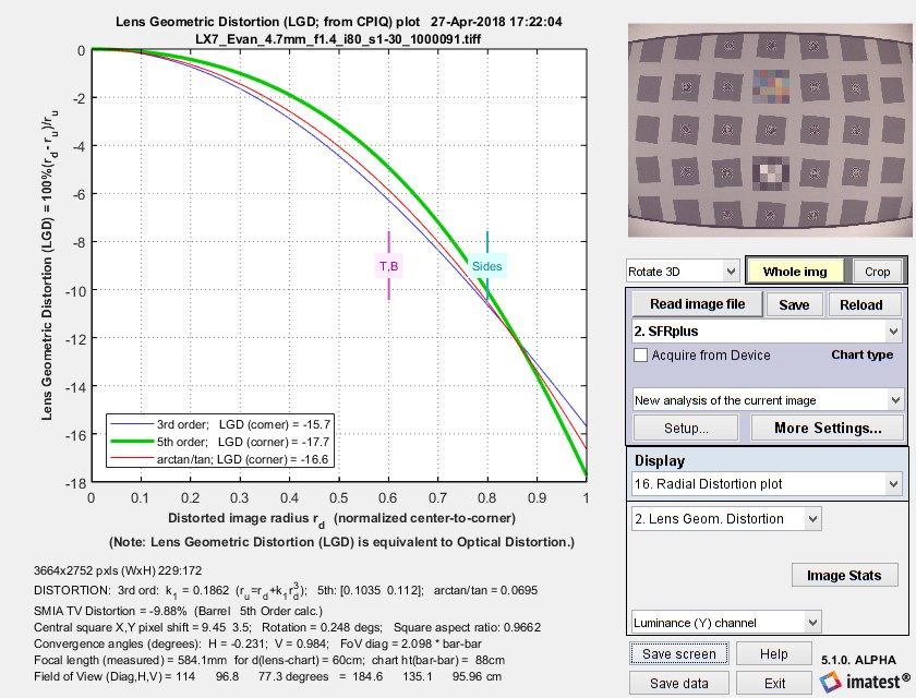
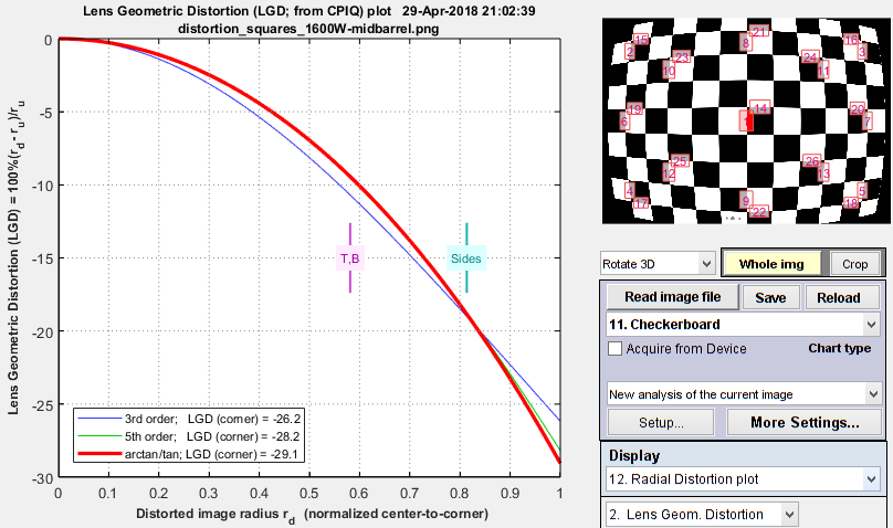
A set of images for comparing different Imatest distortion calculations can be downloaded by clicking on distortion_comparison_barrel_pin.zip. These images were created by the Test Charts module, converted to bitmaps of equal size, then equally distorted. The zip file includes barrel and pincushion-distorted images for Distortion, Checkerboard, Dot Pattern, SFRplus, and eSFR ISO. As the Lens Geometrical Distortion figures for the modules show, agreement is excellent. The Dot Pattern module uses the algorithm specified in the Camera Phone Image Quality (CPIQ) specification, but the other modules produce equivalent results.
Notes: the third order calculations (Distortion and SFRplus) are less accurate than the fifth order and arctan/tan calculations (i.e., they cannot be as good a fit to the actual distortion.) The green line (SMIA TV Distortion) in the Dot Pattern figure cannot be compared with the other figures.
Photography or image pickup with a video camera has been common in microscopy and thus a clear, sharp image over the entire field of view is increasingly required. Consequently, Plan objective lenses corrected satisfactorily for field curvature aberration are being used as the mainstream. To correct for field curvature aberration, optical design is performed so that Petzval sum becomes 0. However, this aberration correction is more difficult especially for higher-magnification objectives. (This correction is difficult to be compatible with other aberration corrections) An objective lens in which such correction is made features in general powerful concave optical components in the front-end lens group and powerful concave ones in the back-end group.
High powerobjective microscopefunction
Objectivelensmicroscopefunction
Field of view (FoV) is calculated for SFRplus, Checkerboard, and eSFR ISO by applying the distortion model equation to the top, side, and diagonal (always r = 1) of the image. In order to calculate FoV in units of distance (cm) a chart geometrical distance has to be entered into the Rescharts More settings window.
The box on the right is described in the SMIA spec as “nearly filling” the image. Since the test chart grid may not do this, Distortion uses a simulated box whose height is 98% that of the image. Note that the sign is opposite of k1 and p1. SMIA TV Distortion > 0 is pincushion; < 0 is barrel.
At Imatest we have traditionally used the SMIA definition, which has been widely adopted in the mobile imaging industry, because it is self-consistent. In the traditional definition, TV distortion is the change (Δ) of the center-to-top distance divided by by the bottom-to-top distance. In the SMIA definition, both A and B are bottom-to-top distances.
Objectivelensmicroscopemagnification
The purposes of optical microscopes are broadly classified into two; "biological-use" and "industrial-use". Using this classification method, objective lenses are classified into "biological-use" objectives and "industrial-use" objectives. A common specimen in a biological use is fixed in place on the slide glass, sealing it with the cover glass from top. Since a biological-use objective lens is used for observation through this cover glass, optical design is performed in consideration of the cover glass thickness (commonly 0.17mm). Meanwhile, in an industrial use a specimen such as a metallography specimen, semiconductor wafer, and an electronic component is usually observed with nothing covered on it. An industrial-use objective lens is optically designed so as to be optimal for observation without any cover glass between the lens end and a specimen.
Distortion is worst in wide angle, telephoto, and zoom lenses. It often worse for close-up images than for images at a distance. It can be easily corrected in software. For more details see Distortion: Methods and Modules.
Notes: [1] All modules. [2] All except eSFR ISO. [3] Checkerboard and SFRplus. [4] Checkerboard-only. [A] arctan/tan and 3rd order models are inadequate for measuring wave (mustache) distortion. A minimum of a 5th order polynomial is required.
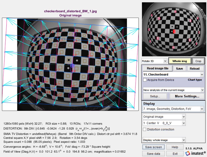
An image display is available in most modules that calculate distortion. In Rescharts it contains a large amount of information (not all distortion-related). Here is an example showing arrows and lines to the corrected image, available for Checkerboard-only. (The arrows & lines can be turned on or off in the More settings window.)
Types ofobjectivelenses
SMIA* TV Distortion is calculated from the distortion model equation (and the Distortion parameters for pre-distorted charts). [*SMIA is the now-defunct “Standard for Mobile Imaging Architecture”, started by Nokia and STMicroelectronics in 2004.]
Lens distortion and coefficients for correcting it are calculated in the Checkerboard module, which calculates 3rd order, 5th order and tangent/arctangent distortion model along with sharpness and several other factors, Dot Pattern performs CPIQ-compliant distortion measurement. SFRplus measure distortion with almost as much detail as checkerboard. SFRplus distortion results are in the Image, Geometry, Distortion, FoV and Radial distortion plots. eSFR ISO measures distortion with slightly less precision than SFRplus.
Shipping Policy | Privacy Policy | Return Policy | Imatest Terms and Conditions
Distortion formulas – Modules – TV Distotion and Field of View – Image, Geometry, Distortion, FoV display Radial distortion plot – Distortion Contour plot – Compare results – Links
Objectivelensmicroscopelabeled
A variety of microscopy methods have been developed for optical microscopes according to intended purposes. The dedicated objective lenses to each microscopy method have been developed and are classified according to such a method. For example, "reflected darkfield objective (a circular-zone light path is applied to the periphery of an inner lens)", "Differential Interference Contrast (DIC) objective (the combination of optical properties with a DIC( Nomarski)prism is optimized by reducing lens distortions)", "fluorescence objective (the transmittance in the near-ultraviolet region is improved)", "polarization objective (lens distortions are drastically reduced)", and "phase difference objective (a phase plate is built in) are available.
Algorithm: SMIA TV Distortion is not actually calculated from the upper and lower bars, whose locations can vary considerably in different images. Instead it is calculated from the distortion coefficients using the selected equation, and using virtual horizontal lines located 1% of the image height below the top and above the bottom of the image.
In the equations which apply to several modules, rd is the distorted (measured) radius normalized to the center-to-corner distance. ru is the undistorted radius. r is normalized to the center-to-corner distance.
Imatest 5.1+ allows you to select between traditional TV distortion (now a part of several ISO standards, including ISO 16505) and SMIA TV distortion. You can make the selection on the left side of the Options II window (button on the lower-right of the Imatest main window). The selection affects only graphic displays (ISO TV distortion = SMIA TV distortion ⁄ 2). Both results are included in CSV and JSON results (for all modules that calculate distortion).
In the optical design of microscope objectives, commonly the larger is an N.A. and the higher is a magnification, the more difficult to correct the axial chromatic aberration of a secondary spectrum. In addition to axis chromatic aberration, various aberrations and sine condition must be sufficiently corrected and therefore the correction of the secondary spectrum is far more difficult to be implemented. As the result, a higher-magnification apochromatic objective requires more pieces of lenses for aberration correction. Some objectives consist of more than 15 pieces of lenses. To correct the secondary spectrum satisfactorily, it is effective to use "anomalous dispersion glass" with less chromatic dispersion up to the secondary spectrum for the powerful convex lens among constituting lenses. The typical material of this anomalous dispersion glass is fluorite (CaF2) and has been adopted for apochromatic objectives since a long time ago, irrespective of imperfection in workability. Recently, optical glass with a property very close to the anomalous dispersion of fluorite has been developed and is being used as the mainstream in place of fluorite.
Objective lenses are roughly classified basically according to the intended purpose, microscopy method, magnification, and performance (aberration correction). Classification according to the concept of aberration correction among those items is a characteristic way of classification of microscope objectives.
Ocular lensmicroscope
The radial distortion plot is available in modules that calculate distortion. This plot has four display options: 1. Delta-r, or 2. Lens Geometric Distortion (LGD), 3. r undistorted (ru), or d(LGD)/d(ru). LGD is shown below.
Lens (optical) distortion is an aberration that causes straight lines to curve near the edges of images. It can be troublesome for architectural photography and photogrammetry (measurements derived from images). The simplest approximation is the 3rd order equation, ru = rd + krd3 where rd is the distorted and ru is the undistorted radius. Depending on the sign of k, it can be either “barrel” (shown on the right) or “pincushion.” A mixture known as “mustache” distortion may occur for complex lenses which are better described by a 5th order approximation (ru = rd+ h1rd3+ h2rd5) .
SMIA TV distortion is twice as large (2X) as traditional TV distortion, now included in several standards. The traditional definition, shown on the right, has been adapted from the publication “Optical Terms,” published by Fujinon. The same definition appears in “Measurement and analysis of the performance of film and television camera lenses” published by the European Broadcasting Union (EBU).
Image Quality Factors for Cameras and Displays Sharpness Noise Dynamic range Color accuracy Distortion Uniformity Blemishes ISO Sensitivity Chromatic Aberration Stray Light (Flare) Moiré Artifacts Compression Losses Dmax (Maximum Density) Color gamut Texture Detail Summary table — corresponding test charts and modules
Axial chromatic aberration correction is divided into three levels of achromat, semiapochromat (fluorite), and apochromat according to the degree of correction. The objective lineup is divided into the popular class to high class with a gradual difference in price. An objective lens for which axial chromatic aberration correction for two colors of C ray (red: 656,3nm) and F ray (blue: 486.1nm) has been made is known as Achromat or achromatic objective. In the case of Achromat, a ray except for the above two colors (generally violet g-ray: 435.8nm) comes into focus on a plane away from the focal plane. This g ray is called a secondary spectrum. An objective lens for which chromatic aberration up to this secondary spectrum has satisfactorily been corrected is known as Apochromat or apochromatic objective. In other words, Apochromat is an objective for which the axial chromatic aberration of three colors (C, F, and g rays) has been corrected. The following figure shows the difference in chromatic aberration correction between Achromat and Apochromat by using the wavefront aberration. This figure proves that Apochromat is corrected for chromatic aberration in wider wavelength range than Achromat is.
The solid lines show results for correction formulas: ru = rd + k1 rd3 (3rd order polynomial; blue); ru = rd + h1 rd3 + h2 rd5 (5th order ploynomial; green); or the arctan/tan equations (red). The best fit (5th order in this case) is shown in bold. With these equations |Δr| often increases as a function of r(distorted), i.e., it tends to be largest near the image corners. The selected value (or the one with the least error, err) is shown in boldface.
Terms Of Use | Privacy Notice | Cookies | Cookie Settings | About Us | Careers | Careers | Sitemap


 Ms.Cici
 8618319014500