
IR Sensing and Detection Filters - ir bandpass filter
If an aspherical lens with high NA (> 0.55) is used as focusing optics, how is the beam divergence angle defined after beam focus? Would it be possible to determine the angle directly via the NA?
An important issue is the power budget of a free-space link, including the transmitter power and all power losses. The remaining power at the receiver largely is a key factor for the possible data rate, although this is also influenced by the modulation format, the acceptable bit error rate, and various noise sources, in particular laser noise, amplifier noise, excess noise in the receiver (e.g. an avalanche photodiode), and background light. The latter can often be effectively suppressed with additional narrowband optical filters, since the optical bandwidth of the signal is quite limited, while background light is usually very broadband.
The encyclopedia covers this topic well: with a long overview article on laser material processing and specialized articles on
By submitting the information, you give your consent to the potential publication of your inputs on our website according to our rules. (If you later retract your consent, we will delete those inputs.) As your inputs are first reviewed by the author, they may be published with some delay.
Would it be possible to relate the mode diameter of a single mode photonic crystal fiber to its numerical aperture? In other terms, can we use the divergence angle of a Gaussian beam focused to be the same size of the fiber mode to infer the numerical aperture of the fiber?
In the case of a step-index fiber, one can define the numerical aperture based on the input ray with the maximum angle for which total internal reflection is possible at the core–cladding interface:
The numerical aperture (NA) of the fiber is the sine of that maximum angle of an incident ray with respect to the fiber axis. It can be calculated from the refractive index difference between core and cladding, more precisely with the following relation:
Free spaceopticalcommunicationprojects
However, your question is probably how the divergence of the light emerging from the fiber output depends on the divergence of the launched input beam. That divergence is limited by the fiber's NA, but can also depend on the launch conditions if it is a multimode fiber. Tentatively, you get a lower divergence out if you launch a low-divergence input beam, but this is not always strictly so. For example, higher-order fiber modes, which lead to larger divergence, may be obtained if you launch a low-divergence input beam at some anger against the fiber axis, or if mode mixing arises e.g. from bending of the fiber.
Free SpaceOptics companies
As an rule of thumb, the half-angle beam divergence in radians should not exceed the NA of the fiber, regardless of the core diameter. Then you should be able to get most of the light launched, assuming that is also all hits the fiber core at the interface.
where <$D$> is the aperture diameter, <$f$> the focal length and <$\lambda$> the optical wavelength. Note that the calculation is based on the paraxial approximation and therefore not accurate for cases with very high NA.
If a beam from a laser diode gets launched into a fiber with a NA (which fits to the fiber), will the output have the same NA?
Here you can submit questions and comments. As far as they get accepted by the author, they will appear above this paragraph together with the author’s answer. The author will decide on acceptance based on certain criteria. Essentially, the issue must be of sufficiently broad interest.
It is also advantageous to have a high directionality on the receiver side: it is important not only to collect as much of the transmitter power as possible, but also to minimize interference, e.g. from background light, which introduces noise and thus reduces the data transmission capacity. Both high sensitivity and high directionality can be achieved by using a large telescope at the receiver end.
Free SpaceOptics equipment
In the case of a multimode fiber, the problem is that the beam quality will depend on the unknown power distribution over the fiber modes. The article on multimode fibers contains a formula with which we estimate <$M^2$>.
You can just take the NA of one fiber (assuming that all fibers are having the same NA). The angular limitations of the bundle are the same as those for each fiber.
Using our advertising package, you can display your logo, further below your product description, and these will been seen by many photonics professionals.
How is the output beam divergence influenced when you have two fibers of different NAs coupled to one another? Is the beam divergence limited by the smallest NA in a fiber coupled system?
For efficient launching, the NA of the collimator should be at least as large as that of the fiber. A larger value won't hurt. A too small value leads to imperfect collimation, including an increased beam divergence.
How to control the divergence angle from a multimode optical fiber, by changing light launched condition or selecting fibers with different NA.
If I want to transmit both 1050 nm and 1550 nm through the same fiber, how do NA, MFD and collimation change for the two wavelengths?
In photography, it is not common to specify the numerical aperture of an objective because such objectives are not thought to be used with a fixed working distance. Instead, one often specifies the aperture size with the so-called f-number, which is the focal length divided by the diameter of the entrance pupil. Usually, such an objective allows the adjustment of the f-number in a certain range.
Some space applications require large amounts of data to be transmitted. An example is the transmission between different satellites in Earth orbit (inter-satellite communications), which was first demonstrated by ESA in 2001 (ESA). It is possible to transmit tens of megabits per second or more over many thousands of kilometers using moderate average laser power on the order of a few watts.
Using our advertising package, you can display your logo, further below your product description, and these will been seen by many photonics professionals.
Why do we define the numerical aperture of a fiber in this way? Is there any reason that we call it numerical aperture? Does it have a certain relation with the numerical aperture of a lens?
Note: this box searches only for keywords in the titles of articles, and for acronyms. For full-text searches on the whole website, use our search page.
The output is a beam, and that cannot have a numerical aperture, but only a beam divergence. So your question should be whether the beam divergence is determined by the NA of the fiber.
The equation given above holds only for straight fibers. For bent fibers, some modified equations have been suggested, delivering a reduced NA value, called an effective numerical aperture of the bent fiber. Proper references for such equations are missing at the moment.
The required laser powers are very moderate, since a significant part of the transmitted power can hit the receiver (e.g. a photodiode). Therefore, there are usually no significant laser safety issues, especially if eye-safe lasers emitting in the 1.5μm spectral range are used. However, the availability of services is less than with a cable, as the link can be disturbed by either atmospheric influences (e.g. heavy rain, fog, snow, or strong wind) or flying objects such as birds and drones. In this respect, free space transmission is less robust than other wireless technologies such as radio links, but it has a higher potential for transmission capacity, is immune to electromagnetic interference, and does not raise concerns about electro smog. It also does not cause interference between different data links, so it does not require a license to operate, and it is superior in terms of data security, since it is more difficult to intercept a tightly collimated laser beam than a radio link. Finally, reliability can be improved in several ways, e.g. with multi-beam architectures, larger power margins, and backup systems, and security can be extremely high with certain schemes of quantum cryptography.
There is a weak dependence of numerical aperture on the optical wavelength due to the wavelength dependence of the focal length, which also causes chromatic aberrations.
I am not sure about the origin of the wording. “Numerical” may just relate to “quantitative”, and “aperture” is a kind of limiting device – in this context, limiting not concerning spatial position, but concerning propagation angles. These aspects also apply to the numerical aperture of a lens.
The comment that higher NA decreases optical losses seems misleading as for a multimode fiber higher NA leads to optical path increase inside the core material.
Note: the article keyword search field and some other of the site's functionality would require Javascript, which however is turned off in your browser.
It is often not recommended to operate a lens or its full area, since there could be substantial spherical aberrations. The numerical aperture, however, is a completely geometrical measure, which is not considering such aspects.
The numerical aperture of an optical system is defined as the product of the refractive index of the beam from which the light input is received and the sine of the maximum ray angle against the axis, for which light can be transmitted through the system based on purely geometric considerations (ray optics):
The critical angle for total internal reflection is <$\arcsin(1 / n_\rm{YAG})$>, but note that this is measured against the surface normal. The angle against the rod axis is <$\pi / 2 - \arcsin(1 / n_\rm{YAG})$>, and the sine of that gives you the NA.
Severe challenges can arise from the effects of atmospheric disturbances such as clouds, dust, and fog, which can cause not only strong signal attenuation but also intersymbol interference. To solve this problem, sophisticated digital signal processing techniques have been developed that, amazingly, allow reliable high-capacity optical links even through dense clouds. In some situations, adaptive optics can also be very helpful.
The TILBA product line improves the reliability of laser communications. TILBA-ATMO optimizes free-space optical links with its simple yet robust high-performance solution to compensate for atmospheric turbulence.
Assuming a Gaussian laser beam with e.g. an initial NA of 0.1 passes through a lens with e.g. NA = 0.7, what is the resulting NA after the lens to describe the waist radius?
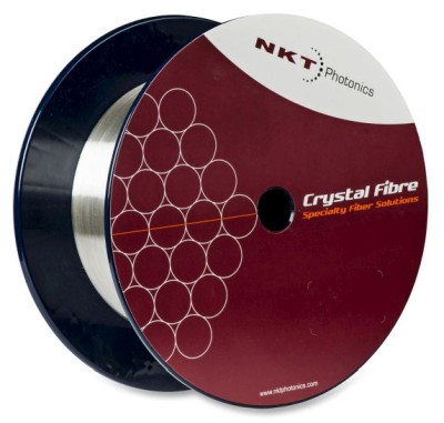
Our large mode area photonic crystal fibers are designed for diffraction-limited high-power delivery. The large mode area prevents nonlinear effects and material damage. With standard fibers, you trade large mode areas for single-mode operation. With our large mode area fibers, you get single-mode operation in a wide range of wavelengths. Also available in a polarization-maintaining version.
How does the NA change as one moves out of the nominal operating wavelength range? I have got a telecom fibre for 1300–1600 nm (NA = 0.14) and launch visible light into it.
Particularly, if it is a single-mode waveguide, the optimum coupling tells us that there you have best matching to the guided mode of the waveguide. Then you will have a similar mode profile at the output of the waveguide. The divergence in air should then be roughly the same as that of the laser beam. This is not exact, however, since the shape of the waveguide mode may somewhat differ from that of the laser beam.
Light propagation in most optical fibers, and particularly in single-mode fibers, cannot be properly described based on a purely geometrical picture (with geometrical optics) because the wave nature of light is very important; diffraction becomes strong for tightly confined light. Therefore, there is no close relation between properties of fiber modes and the numerical aperture. Only, high-NA fibers tend to have modes with larger divergence of the light exiting the fiber. However, that beam divergence also depends on the core diameter. As an example, Figure 3 shows how the mode radius and mode divergence of a fiber depend on the core radius for fixed value of the numerical aperture. The mode divergence stays well below the numerical aperture.
In the example case above, the numerical aperture of the lens is determined by its diameter and its focal length. Note, however, that a lens may not be designed for collimating light, but for example for imaging objects in a larger distance. In that case, one will consider rays coming from that object distance, and the obtained numerical aperture will be correspondingly smaller – sometimes even much smaller. This shows that the numerical aperture depends on the location of some object plane determined by the designer according to the intended use.
free-spacelaser communicationpdf
The extreme rays are limited by the size of the lens, or in some cases somewhat less if there is a non-transparent facet.
If you had an end face, you could couple in light even with large incidence angles. However, you probably mean ring resonators, where you do not have an end face to couple in. The coupling is then usually done via evanescent waves, and that may be hard because the evanescent field decays so fast.
In many cases, the light input comes from air, where the refractive index is close to 1. The numerical aperture is then necessarily smaller than 1, but for some microscope objectives it is at least not much lower, for example 0.9. Other microscope objectives for particularly high image resolution are designed for the use of some immersion oil between the object and the entrance aperture. Due to its higher refractive index (often somewhat above 1.5), the numerical aperture can then be significantly larger than 1 (for example, 1.3).
The NA is a property of the lens, while the beam divergence depends on other factors such as the beam radius before the lens. So you can generally not do that calculation. At most, you can calculate the maximum beam divergence angle with is possible without excessive aberrations.
In your discussion on the NA of a lens above you provide the equation <$w_\textrm{lens} = D / 4 = NA \cdot f / 2$>. Why is there a 1/2 factor in the NA definition? Does this mean NA is normally full angle for lenses?
A smaller NA can reduce the divergence angle (set a limit to it), but may make it more difficult to get enough light into the fiber. Alternatively, you try to inject light with smaller divergence, while also avoiding tight bending.
One might expect to obtain a tighter focus after the lens if the input light is already converging. However, the convergence angle of the light after the lens is limited by the NA of the lens. Trying to operate a lens in that way would mean that you violate its specifications, and the result would probably be substantial beam distortions, which may well prevent you from getting a tighter focus.
Free space laser communicationcompanies
Please do not enter personal data here. (See also our privacy declaration.) If you wish to receive personal feedback or consultancy from the author, please contact him, e.g. via e-mail.
For not too long distances (e.g. up to a few kilometers) and moderate data rates, one does not even need a laser transmitter, because light-emitting diodes can be used.
There exist microresonators based on silicon nitride as the core (n 2.0) and silica as the cladding (n 1.5). This leads to a NA around 1.32. What does it mean? No light could be sent in/out from/to air?
Normally, that should not be the case. It would require that the refractive index contrast between core and cladding changes, and that is unusual. It may happen that the core diameter somewhat varies, but that does not influence the numerical aperture.
Note that the NA is independent of the refractive index of the medium around the fiber. For an input medium with higher refractive index, for example, the maximum input angle will be smaller, but the numerical aperture remains unchanged.
I see, the idea is that light may do more of a zig-zag path, which is longer than a straight path through the fiber. However, that argument is questionable; for example, consider that light in any guided fiber mode does not perform a zig-zag path; it has wavefronts perpendicular to the fiber axis and propagates strictly in that direction. Only for light rays (which are anyway a problematic concept for fibers), you can imagine an increased path length, and that would be a quite weak effect. Anyway, other aspects as explained in the article are definitely more important.
If it is a single-mode fiber, the <$M^2$> value will be close to 1, somewhat dependent on the mode shape, which can be calculated from the index profile.
Enter input values with units, where appropriate. After you have modified some inputs, click the “calc” button to recalculate the output.
Occasionally, the literature contains statements on the numerical aperture of a laser beam. This use of the term is actually discouraged because the numerical aperture should be considered to be based on ray optics, which cannot be applied here. Still, it can be relevant to understand what is meant with such a statement. Here, the numerical aperture is taken to be the tangent of the half-angle beam divergence. Within the paraxial approximation, the tangent can be omitted, and the result is <$\lambda / (\pi w_0)$> where <$w_0$> is the beam waist radius.
Is there any reason an extrusion process for a plastic optical fiber would expect to change index of refraction of either core or cladding materials? It seems that if core and cladding IORs are both known, that calculating/predicting NA for a plastic multi-mode fiber should be highly consistent. When measuring finished samples, however, it seems that the numerical aperture fluctuates about 20%. What would be the reasons for fluctuations in measured NA? Could it be that the test system isn’t gauged properly, or have you seen in your experience that NA values will vary even though the theoretical value based on IORs should be consistent?
Please do not enter personal data here. (See also our privacy declaration.) If you wish to receive personal feedback or consultancy from the author, please contact him, e.g. via e-mail.
Note: the article keyword search field and some other of the site's functionality would require Javascript, which however is turned off in your browser.
At a first glance, you may think it is not possible, since the refractive index contrast stays the same – but it can actually change into different ways:
By submitting the information, you give your consent to the potential publication of your inputs on our website according to our rules. (If you later retract your consent, we will delete those inputs.) As your inputs are first reviewed by the author, they may be published with some delay.
Is there an equation relating the numerical aperture and far-field intensity distribution for a single-mode fiber, like figure 4, or does it need to be modelled in detail for each case?
Here you can submit questions and comments. As far as they get accepted by the author, they will appear above this paragraph together with the author’s answer. The author will decide on acceptance based on certain criteria. Essentially, the issue must be of sufficiently broad interest.
The relation between the numerical aperture and the beam divergence angle of an output beam emerging from a fiber end is generally not trivial:
The numerical aperture (NA) of an optical system (e.g. an imaging system) is a measure for its angular acceptance for incoming light. It is defined based on geometrical considerations and is thus a theoretical parameter which is calculated from the optical design. It cannot be directly measured, except in limiting cases with rather large apertures and negligible diffraction effects.
Presumably, you wonder whether the NA determines the beam divergence in free space. The answer is no for single-mode fibers. See also our case study on the numerical aperture.
For shorter-wavelength light, the refractive indices of core and cladding will generally increase, and the NA will presumably also increase somewhat. For example, for germanosilicate fibers that would be the case.
Using the term numerical aperture for laser beams is actually discouraged. I assume, however, that you mean the divergence angle of a beam which is convergent on the way to the lens.
For a single-mode fiber, the NA is typically of the order of 0.1, but can vary roughly between 0.05 and 0.4. (Higher values lead to smaller effective mode areas, smaller bend losses but to tentatively higher propagation losses in the straight form due to scattering.) Multimode fibers typically have a higher numerical aperture of e.g. 0.3. Very high values are possible for photonic crystal fibers.
Free spaceoptical
No, that factor results from the assumption that the beam radius is chosen to be only half the NA in order to avoid substantial beam clipping and aberrations.
What is the equation that relates the divergence of the laser beam to the fiber core (105 μm) and the numerical aperture of the optical fiber?
Could you comment on the effect of the clear aperture of the lens (provided by manufacturers), and the impact of spherical aberrations for w = D/4 vs. D/3 (99.9% vs. 99% transmitted of a Gaussian beam)?
Let's assume that we have a diode laser with fiber output, which has a certain NA and core diameter. How to determine its BPP or M2?
The requirement of total internal reflection would seem to set a strict limit for the angular distributions of fiber modes. However, some modes are found to exceed that limit significantly. We investigate that in detail for single-mode, few-mode and multimode fibers.
Note: this box searches only for keywords in the titles of articles, and for acronyms. For full-text searches on the whole website, use our search page.
Exail (formerly iXblue) offers a wide range of specialty optical fibers for lasers and amplifiers. We master erbium, erbium/ytterbium, ytterbium, thulium, holmium, thulium/holmium, neodymium, dysprosium, and phosphorous gain media. PM version are available, and Large Mode Area (LMA) or Very Large Mode Area (VLMA) versions as well. Depending of the requirement, single clad fibers are available for core pumping, double clad fibers for clad pumping. Triple clad and all glass structures are also available.
You cannot calculate the NA for that case. It is only defined for a step index fiber, meaning the core and cladding index are constant. But you may of course take the average values over some range to get an approximation.
Much less technologically challenging are data links between buildings in large cities (LAN-to-LAN connections), where a free-space laser data link over distances of hundreds of meters or even a few kilometers can be much easier and less expensive to install than any kind of cable, especially if a road or other barrier has to be crossed, or if the connection is only needed for a limited period of time. It is then possible, for example, to provide fast Internet access to all buildings involved, even if only one of them has direct access to a fiber optic network.
Free spaceOptics technology
In principle yes, if you apply the technique of mode division multiplexing: an increased numerical aperture gives you more modes and therefore in principle a potential for higher data rates.
The numerical aperture of such a fiber is simply not defined. At least, I am not aware of a reasonable way of defining it.
Although an optical fiber or other kind of waveguide can be seen as a special kind of optical system, there are some special aspects of the term numerical aperture in such cases.
That's a good approach. With that NA, it should work for any launch conditions. For favorable launch conditions, it can work even with a lower lens NA.
Especially for large transmission distances, it is essential to direct the energy of the transmitter in the form of a well-collimated laser beam to limit the often still very large power loss between transmitter and receiver. To limit the beam divergence, it is necessary to provide a large beam radius from an optical source with high beam quality. Ideally, one uses a diffraction-limited source and a large, high-quality large optical telescope to collimate the beam. Due to the short wavelength of the light, the beam divergence of an optical transmitter can be much smaller than that of a radio or microwave source of similar size. To use a term commonly used in the field of radio communications, the antenna gain of an optical telescope can be very high – well over 100 dB even for moderate telescope diameters of, say, 25 cm – and thus much higher than for any microwave antenna of limited size.
Indeed, some of the light will then be lost, i.e., not get into the guided mode. You can fully launch into the fundamental mode only if you have the perfect amplitude profile, including flat phase fronts perpendicular to the core axis. Particularly for single-mode fibers, the numerical aperture is not providing an accurate criterion.
The clear aperture defines the area to which the light should be restricted. That does not directly translate into a limit for Gaussian beams, which do not have a clear boundary. One will usually limit the Gaussian beam radius to be significantly below that aperture radius – e.g. 2/3 of it.
Advantages offree spaceopticalcommunication
Data can also be exchanged between a more distant spacecraft and a station on or near Earth. For example, planetary probes can generate large amounts of image data, and a major challenge is to send large amounts of data back to Earth. Until recently, the only available technology was radio links operating in the X- or Ka-band. Currently, optical data links are being considered primarily for the downlink, where the desired data volumes are much larger than for the uplink, and optical communications could greatly increase the transmission capacity to many megabits per second. The spacecraft then has a pulsed laser source (e.g. using pulse position modulation) and a moderate-sized optical telescope aimed at the receiver. The latter may be a large ground-based telescope or an Earth-orbiting transceiver.
The answer to that question is no – it generally the beam divergence also depends on the launch conditions, unless you have a single-mode fiber, where the output beam divergence is determined only by the fiber properties, but not specifically by the NA.
Evolution of output power and gain when an Yb-doped fiber laser is switched on. One can see the relaxation oscillations, with convergence towards the steady state. Each red or gray segment corresponds to 0.2 μs.
The main advantages of laser data links over radio frequency (RF) or microwave links are the possible high data rate, low power requirements, compact size, and lower probability of signal eavesdropping by unauthorized parties. In addition, there is no need for government frequency allocation and no risk of mutual interference between different laser data links.
If I have a light beam entering an optical fiber at a slight angle to the optic axis, is all of this beam collected by the SM fiber (ignoring the 4% reflection)? The light path is still well within the numerical aperture of the fiber, but is nevertheless some of the light lost to the coating because the light is not absolutely on axis?
The basic advantage of optical technology over radio is that the much shorter wavelength allows much more directional sending and receiving of information, resulting in much lower power requirements and higher data rates. This is especially important for bridging interplanetary distances. On the other hand, optical links are substantially more sensitive to weather conditions.
If you don't use that technology, however, it is usually better to have a single-mode fiber. Therefore, the numerical aperture should not be too large.
Ask RP Photonics for advice on free-space communication systems – e.g. concerning the selection or design of a suitable laser source, various noise issues, or beam quality requirements.
A somewhat smaller spot size may be possible with correspondingly larger input beam radius, if the performance is not spoiled by aberrations. In case of doubt, one should ask the manufacturer what maximum input beam radius is appropriate for a certain lens.
For the maximum incidence angle, it is demanded that the light can get through the whole system and not only through an entrance aperture.
Let us assume that I have a certain waveguide, where we know that the optimal coupling between laser and the waveguide can be reached when the beam waist at the focal point has a diameter of 38.4 μm. Can we somehow predict the divergence of the output ray at the exit of the waveguide?
Serving North America, RPMC offers a range of lasers, laser amplifiers, and laser diodes used for free-space optical communications. These lasers are available with IR (eye-safe) wavelengths and with different output powers. We have experience with space qualification for intra-satellite free-space communications, and can provide standard and custom solutions to meet your exact requirements. Let RPMC help you find the right laser today!
Does the numerical aperture of the fiber need to match the numerical aperture of a collimator and objective lens? Does the mismatch of numerical aperture result in higher divergence of the output beam?
For fibers or other waveguides not having a step-index profile, the concept of the numerical aperture becomes questionable. The maximum input ray angle then generally depends on the position of the input surface. Some authors calculate the numerical aperture of a graded-index fiber based on the maximum refractive index difference between core and cladding, using the equation derived for step-index fibers. However, some common formula in fiber optics involving the NA can then not be applied.
The same kind of considerations apply to microscope objectives. Such an objective is designed for operation with a certain working distance, and depending on the type of microscope with which it is supposed to be used, it may be designed for producing an image at a finite distance or at infinity. In any case, the opening angle on which the numerical aperture definition is based is taken from the center of the intended object plane. It is usually limited by the optical aperture on the object side, i.e., at the light entrance.
How to calculate the NA of a step index profile fiber if the core and cladding refractive index is not flat along radial direction?
Some lenses are used for focusing collimated laser beams to small spots. The numerical aperture of such a lens depends on its aperture and focal length, just as for the collimation lens discussed above. The beam radius <$w_\textrm{lens}$> at the lens must be small enough to avoid truncation or excessive spherical aberrations. Typically, it will be of the order of half the aperture radius of the lens (or perhaps slight larger), and in that case (<$w_\textrm{lens} = D / 4 = {\rm NA} \cdot f / 2$>, with the beam divergence angle being only half the NA) the achievable beam radius in the focus is
There is only a weak dependence of numerical aperture on the optical wavelength due to chromatic dispersion. For example, the NA of a telecom fiber for the 1.5-μm region is not significantly different from that for the 1.3-μm region.
I suppose you mean the NA of an optical system. The answer: theoretically yes, practically no, it probably can't be that high.
According to my knowledge, the numerical aperture of a photonic crystal fiber is not even clearly defined. Some people take it to be the sine of the half divergence angled of a mode, but I don't consider that as appropriate, particularly because the results for a simple step-index fiber do not agree. In science, we should not use conflicting definitions of the same term.
For a homogeneous fiber without a core region, the surrounding medium (e.g. air) is effectively the cladding, and the NA is then typically rather high. In that case, of course, the refractive medium of the surrounding medium matters.
It is even possible to establish short-range optical data links without a direct line of sight. If ultraviolet light is used, it is highly scattered in the atmosphere, and it is possible to receive some of that light. This technology has become more interesting with the advent of deep-UV (UV-C) light-emitting diodes (LEDs) and suitable semiconductor photodetectors.
In Figure 4 one can see that the angular intensity distribution somewhat extends beyond the value corresponding to the numerical aperture. This demonstrates that the angular limit from the purely geometrical consideration is not a strict limit for waves.
If I need to collimate the beam from a multimode fiber, should I use an aspheric lens with a NA matched that of the MM fiber?
In most cases, optical data transmission on Earth is done using fiber optics, because these allow transmission over relatively long distances without excessive power loss, alignment problems, and interference from the atmosphere. However, it is also possible to transmit data optically through free space (or similarly through water) without using any kind of waveguide structure. This type of optical communication has early origins, e.g. Alexander Graham Bell's “photophone” patent in the 1870s and the optical telegraph, and is now increasingly used both in space and on Earth. It usually requires an unobstructed line of sight between sender and receiver, and usually also some special free-space optics such as telescopes. The light source used nowadays is almost always some kind of laser (possibly combined with an amplifier), because the high directionality of a laser beam is obviously an essential ingredient for high-performance communication. The prominent role of a laser is emphasized by the term laser communications.
Of course, high directionality also implies the requirement of high precision in the alignment of the transmitter and receiver. It may be necessary to stabilize the alignment with an automatic feedback system. For ground-based receivers of signals from remote satellites (see below), one may use adaptive optics to further increase the directionality by reducing the influence of atmospheric disturbances.


 Ms.Cici
 8618319014500