
Infra® SWIR Lenses | Over 10 Shortwave Infrared Lenses - infrared lenses

Shallowdepth of field
Choose products to compare anywhere you see 'Add to Compare' or 'Compare' options displayed. Compare All Close
DOF = Depth of Field in mm λ = Wavelength of the light used in mm. n = Index of refraction NA = Numerical aperture of the objective used
Yes, opt-in. By checking this box, you agree to receive our newsletters, announcements, surveys and marketing offers in accordance with our privacy policy
Depth of field equationpdf
Skipping one of the 0.00055mm steps that I used means that the step size is approximately 0.0011mm. In the video below you can see that this is (barely) visible. The video shows two alternating stacks. In one of them one single photo is deleted. At this enlargement the area used from one photo is just a thin band of sharp pixels. The difference with and without one photo is a small flickering band of sharp/unsharp.
Deepdepth of field
Bandpass filters isolate a band of wavelengths from the total spectrum by providing a band of high transmission and bands of high rejection of spectral energy on both the long and short wavelength sides of the transmission band. These optical filters are defined by cut-on and cut-off slopes establishing the transition between high rejection and high transmission. Bandpass filters can be manufactured with a wide variety of performance attributes ranging from the simplest single-cavity, unblocked Fabry-Perot construction, to the more complex multi-cavity, fully-blocked, all-dielectric, single-substrate construction. Bandpass filters are widely deployed in many diverse applications including paint-color formulation, blood chemistry analysis, and traffic control.
When increasing the resolution from 2µm to 1µm the largest step size decreases from 0.028mm to 0.006mm. For an object that is 1mm from top to bottom the NA 0.15 objective needs at least 36 steps/pictures (1/0.028) and the NA 0.30 needs at least 167 (1/0.006) steps/pictures. Using a smaller step size to have some overlap increases the necessary steps/photos even more.
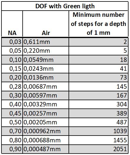
Table 1 shows some example calculations of DOF with green light and air. I usually chose a smaller step size than the calculated DOF for green light. Below is an example of two butterfly wing scales that are upside down. This is a focus stack with 255 photos, 0,00055 mm step size, Nikon BD plan apo 40x NA 0.80 microscope objective, Canon 6D camera, stacked in Zerene Stacker.
Depth of fieldphotography
Depth of field equationcalculator
Vissible light goes from violet approximately 0.380-0.450µm to red approximately 0.625-0.740µm. Green ligth is approximatlelight 0.500-0.565µm. Green light or 0.550µm (0.000550 mm) is a good starting point for the calculations.

Example calculations of Depth of Field (DOF) using a simplified formula for DOF and using the wavelength (λ) for green light 0.550µm. Case #1: NA=0.14 for example Mitutoyo M plan 5xDOF = 0.550µm / 0,14^2 ≈ 28µm or 0.028mm
Depth of field equationexample
For higher NA and or for other media than air I recommend the formula from the article “Depth-of-Focus in Microscopy” written by I.T. Young, R. Zagers, L.J. van Vliet, J. Mullikin, F. Boddeke, H. Netten. To get the “normal” 2-sided DOF I have multiplied their formula with a factor 2.
In practice the step size in focus stacking is usually a bit smaller than the calculated DOF. The reason for this is to have some overlap between the in-focus areas.
Numerical aperture (NA) can be used to calculate the Depth of Field (DOF). Calculating DOF is useful for deciding the (largest) step size for focus stacking.
This website uses affiliate links. If you use affiliate links the vendors will use cookies to track that you came from this website. This website uses cookies to personalise content and ads, to provide social media features and to analyse our traffic. By choosing “Allow” or by using this site, you are agreeing to our use of cookies.
Bandpass filters isolate a band of wavelengths from the total spectrum by providing a band of high transmission and bands of high rejection of spectral energy on both the long and short wavelength sides of the transmission band. These optical filters are defined by cut-on and cut-off slopes establishing the transition between high rejection and high transmission. Bandpass filters can be manufactured with a wide variety of performance attributes ranging from the simplest single-cavity, unblocked Fabry-Perot construction, to the more complex multi-cavity, fully-blocked, all-dielectric, single-substrate construction. Bandpass filters are widely deployed in many diverse applications including paint-color formulation, blood chemistry analysis, and traffic control.


 Ms.Cici
 8618319014500