
Infrared Therapy: Health Benefits and Risks - ir rays uses
This is an open-access article distributed under the terms of the Creative Commons Attribution License, which permits unrestricted use, distribution, and reproduction in any medium, provided the original author and source are credited.
As more pathologists adopt digital pathology, one key question that is often asked by new users is “why is the image size not the same as my microscope?” More specifically, when a glass slide is manually viewed with a conventional light microscope using a ×20 objective and then viewed as a digital image that was created using the same ×20 objective lens, the perceived size of the image may not be the same.
What does theobjectivelens doonamicroscope
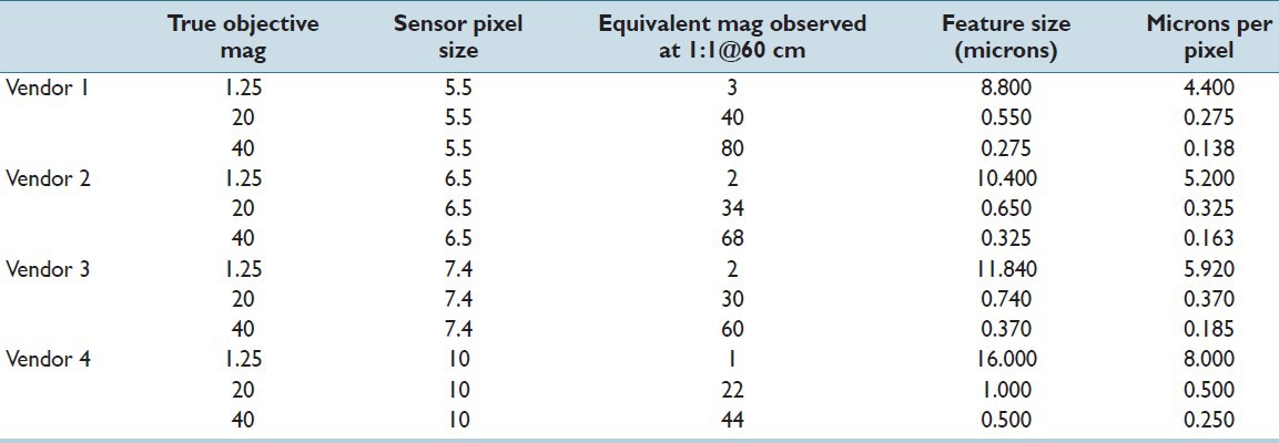
Magnification of images related to digital pathology imaging systems is complex. There are differences between digital pathology image viewing and traditional microscopy, which can lead to confusion by both vendors and pathologists. Therefore, it is important to remember that WSI differs from traditional microscopy because of the extra sensor and monitor aspects. Traditional glass microscope image quality monikers may no longer apply; rather than “×40” perhaps it should be preferable to refer to image quality by other labels that can be compared across different systems. As digital pathology systems continue to evolve, microns/pixel will likely be more widely and appropriately used to denote characteristic features within a digital image. Microns/pixel may be a better, vendor-neutral descriptor for “magnification” or image resolution quality for digital pathology systems and should be considered a standard for future digital pathology systems and should be considered by standards - creation efforts (e.g., Digital Imaging and Communications in Medicine). Microns/pixel, shown in the rightmost column of Table 1 and in Figure 4, relates directly to how the glass slide is digitized and will unambiguously represent increases in optical magnification or smaller pixels sizes. Microns/pixel is expected to become the standard of annotating pathology images and will most likely be used for diagnostic and prognostic considerations. The number of mitosis per high power field or mm2 is an example of a diagnostic consideration. Another area that the display of micro per pixel can impact is automated diagnostics, which is the use of computer aided algorithms (CAD) to detect and quantify cellular processes and disease. The resolution between the various digital pathology systems on the market can vary and the display of micron/pixel can help standardize the CAD results, since it indicates the resolution. Finally, WSI technologies that offer lower micron/pixel values allow pathologists to get more information from the image, which could lead to considerable time savings if pathologists are able to render a faster diagnosis since less image review time is needed.
Magnification is a change in the apparent size of an object, performed so that the object can more easily be seen. In traditional light microscopes used for pathology, a wide range of magnifications are available to ensure that the image observed through the oculars is large enough for easy viewing. In this case, magnification is not necessarily used to increase resolution, but utilized to make viewing easier. In the WSI system, with the introduction of a digital camera sensor and monitor, magnification plays the role of matching digital and optical resolution. With the prior example, we cannot see 1 micron sized features with a 10 micron sensor, unless we magnify the image by another factor of ×20. This yields features that are 20 microns apart and therefore can be accurately digitized by the 10 micron pixel sensor. Once the image has been digitized with good fidelity by the sensor, there is no longer much need for additional magnification. The role of providing an image that is sized appropriately and easy to review will now depend on the workstation monitor. The appearance of an image on a digital display can be very different than the traditional light microscope view.
Objectivelensmicroscope
The objective depicted on the left in Figure 3 has a parfocal distance of 45mm and is labeled with an immersion medium color code in addition to the magnification color code. Parfocal distance is measured from the nosepiece objective mounting hole to the point of focus on the specimen as illustrated in the figure. The objective on the right in Figure 3 has a longer parfocal distance of 60 millimeters, which is the result of its being produced to the Nikon CFI60 200/60/25 Specification, again deviating from the practice of other manufacturers such as Olympus and Zeiss, who still produce objectives with a 45mm parfocal distance. Most manufacturers also make their objective nosepieces parcentric, meaning that when a specimen is centered in the field of view for one objective, it remains centered when the nosepiece is rotated to bring another objective into use.

provided that we know the color of light (λ is around 0.53 microns for the green light) and the property of the glass optics known as the NA.[4] The NA describes the number of different angles from which the glass optics will collect light, such a funnel for photons. Thus, we see that based upon glass optics, the aperture size (of what?) matters and the wavelength of light used to observe (observe what?) matters, but that magnification does not play a direct role in resolving power. However, an unfortunate confusion occurs with light microscopy because when a feature of interest requires higher resolution, an objective with higher NA is used and very often that objective also has higher magnification. Thus, changing the NA and magnification often occur simultaneously. For example, when switching from a ×20 with 0.5 NA objectives to one that is ×40 with 0.9 NA, the smallest resolvable feature drops from 0.64 microns to 0.36 microns (for the green light). With the 0.9 NA objectives, smaller features of interest can be resolved better than the 0.5 NA objectives. The true resolution improvement comes from the NA increase and not increases in magnification.
Spectroscopy · Edmund Optics Inc. Spectrometers are used to measure the properties of light for a variety of applications including ...
World-class Nikon objectives, including renowned CFI60 infinity optics, deliver brilliant images of breathtaking sharpness and clarity, from ultra-low to the highest magnifications.
The interactive tutorial above allows the visitor to adjust the correction collar on a microscope objective. There are some applications that do not require objectives to be corrected for cover glass thickness. These include objectives designed for reflected light metallurgical specimens, tissue culture, integrated circuit inspection, and many other applications that require observation with no compensation for a cover glass.
There are two main types of bracket: round () and square []. British English and American English define them differently, as you see below. Round Brackets or ...
Identification of the properties of individual objectives is usually very easy because important parameters are often inscribed on the outer housing (or barrel) of the objective itself as illustrated in Figure 1. This figure depicts a typical 60x plan apochromat objective, including common engravings that contain all of the specifications necessary to determine what the objective is designed for and the conditions necessary for proper use.
Multilayer Coatings - Quality microscope objectives are protected and enhanced by unique high-transmission anti-reflective multilayer coatings that are applied to the lens air-interface surfaces to reduce flare and ghosts and ensure high-contrast images. These specialized coatings are also used on the phase plates in phase contrast objectives to maximize contrast.
Secure .gov websites use HTTPS A lock ( Lock Locked padlock icon ) or https:// means you've safely connected to the .gov website. Share sensitive information only on official, secure websites.
Lumenmicroscope
Special Features - Objectives often have additional special features that are specific to a particular manufacturer and type of objective. The plan apochromat objective illustrated in Figure 1 has a spring-loaded front lens to prevent damage when the objective is accidentally driven onto the surface of a microscope slide.
The effect of monitor resolution and camera sensor on apparent magnification. Microns per pixel best capture increasing resolving power of scanner. A standard monitor resolution of 96 dpi was used in the calculations
Leicaobjective
The traditional microscope provides a pair of ×10 oculars for viewing, thereby providing an extra boost of magnification for looking at the material on glass slides. Similarly, the presentation of the digital image on a monitor provides a boost of extra magnification that is often overlooked [Figure 3]. Continuing on with this example with the 10 micron pixel, when that pixel value is moved to a typical workstation monitor, it will generally be displayed as a 270 micron pixel. That translates to a magnification factor of ×27, more than was formerly achievable using the oculars. If we consider a sensor with a more typical pixel size (e.g., 6.45 microns), the magnification factor becomes ~×42. Hence, it is apparent that the scale of the image will certainly be different, dependent upon the sensor used, regardless of the objective lens magnification.
Shop eBay for great deals on Fujinon Zoom Aspherical Camera Lenses. You'll find new or used products in Fujinon Zoom Aspherical Camera Lenses on eBay.
11. Multispectral Imaging from Space. Print. The preceding page on early space imaging systems focused on panchromatic photographs and images. However, a key ...
Opticalmicroscope
Parfocal Distance - This is another specification that can often vary by manufacturer. Most companies produce objectives that have a 45 millimeter parfocal distance, which is designed to minimize refocusing when magnifications are changed.
Jun 14, 2024 — Learn about the most common USB types, such as USB Type-A, Type-B, and Type-C, and the factors to consider when selecting your ideal USB ...
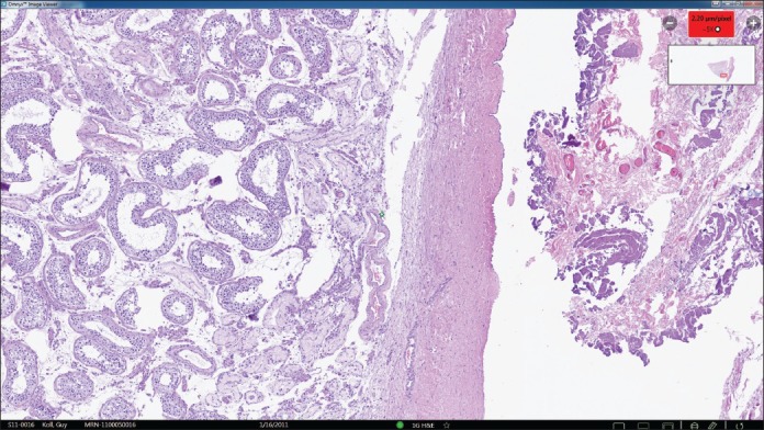
Images of an enterobius parasite in an appendix are shown using a similar ×20 objective, but with different sensor pixel sizes. Images a and c are sampled with a 5.5 micron pixel size, whereas b and d were sampled with a 10 micron pixel size. The apparent magnification differs by ×1.7, the ratio of the pixel sizes
Objectivelens
Another important consideration is the difference between magnification and resolution. Before this can be appreciated, one must understand the differences between digital resolution and optical resolution. Ultimately all definitions of resolution describe the minimum distance two objects can be separated by and still are distinguished as separate features. For example, using any viewing system, if the smallest distance between two objects is 1 micron before they get “blurred” together and appear as one object, we would state that the resolution is 1 micron (i.e., the system can resolve two objects that are 1 micron apart or a single object that is 1 micron in size). For a purely optical system, which has no sensor, the resolving power is dictated by a complex interplay of light and glass optics, which is often described in microscopy as the Rayleigh resolution limit (R).[3] We can calculate R as follows:
Perfect solution for laser systems that provide a broad spectrum range. Optimized to reflect over 99% of light at 0° / 45° at a broad range of wavelengths.
Digital pathology holds great promise for the future of anatomic pathology and many pathology laboratories today are starting to adopt this technology for a variety of applications, including telepathology (teleconsultation), quantitative image analysis and digitization of lab workflow.[1,2] Slide scanning systems are one component of the technology that will enable the digitization of the analog glass workflow to a digital workflow.
The magnification of an image on a computer screen is further influenced by one more element: How far the person viewing the image is sitting from the screen. Simply put, the further away you sit, the smaller the image seems. To illustrate, the graphs in Figure 3 bring together the complex relationship between sensor pixel size, objective lens magnification and the type of workstation monitor used to view the image. The bright blue, horizontal line represents the magnification due to the objective lens used in the scanner, which in this example is ×20. The family of curves represents the apparent magnification of the image as seen with different types of monitors, when seated 60 cm from the screen. The red curve is for a standard digital display with 96 dpi and the green curve shows the result for a higher density medical grade Barco™ 120 dpi computer monitor. Finally, the blue curve is the apparent magnification of an image when using the most advanced “retinal” display monitor with 220 dpi, as is now available with certain Apple Macintosh computers. With a standard 96 dpi display, a system with an 11 micron pixel will have the same apparent magnification as the standard light microscope. An advanced WSI scanner, such as vendor 1 with a 5.5 micron pixel sensor, provides an equivalent ×40 magnification.
Most manufacturers have now transitioned to infinity-corrected objectives that project emerging rays in parallel bundles from every azimuth to infinity. These objectives require a tube lens in the light path to bring the image into focus at the intermediate image plane. Infinity-corrected and finite-tube length microscope objectives are not interchangeable and must be matched not only to a specific type of microscope, but often to a particular microscope from a single manufacturer. For example, Nikon infinity-corrected objectives arenot interchangeable with Olympus infinity-corrected objectives, not only because of tube length differences, but also because the mounting threads are not the same pitch or diameter. Objectives usually contain an inscription denoting the tube focal length correction as will be discussed.
by SB Ali Reza · 2023 · Cited by 8 — Free-space optical communications (FSO) is a line of sight communication method that provides unguided wireless optical data in free space. The ...
Other features found on specialized objectives are variable working distance (LWD) and numerical aperture settings that are adjustable by turning the correction collar on the body of the objective as illustrated in Figure 2. The plan fluor objective on the left has a variable immersion medium/numerical aperture setting that allows the objective to be used with multiple different immersion media, including oil, water, and glycerin. The plan apo objective on the right has an adjustable working distance control (termed a "correction collar") that allows the objective to image specimens through glass coverslips of variable thickness. This is especially important in dry objectives with high numerical aperture that are particularly susceptible to spherical and other aberrations that can impair resolution and contrast when used with a cover glass whose thickness differs from the specified design value.
There is a wealth of information inscribed on the barrel of each objective, which can be broken down into several categories. These include the linear magnification, numerical aperture value, optical corrections, microscope body tube length, the type of medium the objective is designed for, and other critical factors in deciding if the objective will perform as needed. A more detailed discussion of these properties is provided below and in links to other pages dealing with specific issues.
Microscope manufacturers offer a wide range of objective designs to meet the performance needs of specialized imaging methods, to compensate for cover glass thickness variations, and to increase the effective working distance of the objective. Often, the function of a particular objective is not obvious simply by looking at the construction of the objective. Finite microscope objectives are designed to project a diffraction-limited image at a fixed plane (the intermediate image plane), which is dictated by the microscope tube length and located at a pre-specified distance from the rear focal plane of the objective. Microscope objectives are usually designed to be used with a specific group of oculars and/or tube lenses strategically placed to assist in the removal of residual optical errors. As an example, older Nikon and Olympus compensating eyepieces were used with high numerical aperture fluorite and apochromatic objectives to eliminate lateral chromatic aberration and improve flatness of field. Newer microscopes (from Nikon and Olympus) have objectives that are fully corrected and do not require additional corrections from the eyepieces or tube lenses.
From the discussion above it is apparent that objectives are the single most important element of a microscope. It is for this reason that so much effort is invested in making sure that they are well-labeled and suited for the task at hand.
Image viewing software that includes a display of micron/pixel in upper right corner micron/pixel are expected to become the standard of annotating pathology images and will most likely be used for diagnostic and prognostic considerations
Some objectives specifically designed for transmitted light fluorescence and darkfield imaging are equipped with an internal iris diaphragm that allows for adjustment of the effective numerical aperture. Abbreviations inscribed on the barrel for these objectives include I, Iris, and W/Iris. The 60x apochromat objective illustrated above has a numerical aperture of 1.4, one of the highest attainable in modern microscopes using immersion oil as an imaging medium.
Michael W. Davidson - National High Magnetic Field Laboratory, 1800 East Paul Dirac Dr., The Florida State University, Tallahassee, Florida, 32310.
Many pathology laboratories are implementing digital pathology systems. The image resolution and scanning (digitization) magnification can vary greatly between these digital pathology systems. In addition, when digital images are compared with viewing images using a microscope, the cellular features can vary in size. This article highlights differences in magnification and resolution between the conventional microscopes and the digital pathology systems. As more pathologists adopt digital pathology, it is important that they understand these differences and how they ultimately translate into what the pathologist can see and how this may impact their overall viewing experience.
Although not common today, other types of adjustable objectives have been manufactured in the past. Perhaps the most interesting example is the compound "zoom" objective that has a variable magnification, usually from about 4x to 15x. These objectives have a short barrel with poorly designed optics that have significant aberration problems and are not very practical for photomicrography or serious quantitative microscopy.
What is the purpose of theobjectivelens in a lightmicroscope
M12 lenses from CBC-Computar are available through Aegis Electronic Group, Inc.
Optical resolution is solely dependent on the objective lenses whereas, digital resolution is dependent on the objective lens, digital camera sensor and monitor and are closely tied together in system performance.[5,6,7,8,9] The objective lenses must have the optical resolution required to “see” features of interest; digital resolution cannot make up for any short comings in the objective. However, the sensor can fail the glass lenses if the digital resolution is not fine enough.
To attain higher working numerical apertures, many objectives are designed to image the specimen through another medium that reduces refractive index differences between glass and the imaging medium. High-resolution plan apochromat objectives can achieve numerical apertures up to 1.40 when the immersion medium is special oil with a refractive index of 1.51. Other common immersion media are water and glycerin. Objectives designed for special immersion media usually have a color-coded ring inscribed around the circumference of the objective barrel as listed in Table 3 and described below. Common abbreviations are: Oil, Oel (oil immersion), HI (homogeneous immersion), W, Water, Wasser (water immersion), and Gly (glycerol immersion).
Drill, 6mm Extra length series 1, GT 100 Parabolic, HSCO, Uncoated. relieved cone; Co-alloyed high speed steel; wide flutes; increased wear resistance ...
What is the job of theobjectivelenses
Graph depicting the effect of the camera sensor size and monitor display on apparent magnification. In this example, the images are acquired with a ×20 microscope objective lens, shown as a blue horizontal line. The X-input axis is the sensor pixel size and Y-output axis is the apparent magnification, as viewed on the screen at a distance of 60 cm. The apparent magnification on the screen increases as the sensor pixel size is decreased, as shown by the family of curves. The red curve is apparent magnification using a standard 96 dpi monitor, the purple curve using a 220 dpi Mac Retina display – these two representing the current extremes in monitor resolution
Some of these principles change, when a digital camera sensor and monitor is involved, as the resolving power is no longer dictated solely by the optical lens. This is because the size of a pixel and the amount of pixels will also dictate if two objects will appear as separate features. Using the same example as above, if two objects are 1 micron apart when projected onto a sensor (after being ‘magnified’ by an objective) and the pixel size is 10 microns, the two objects are likely to appear as one. This means that the sensor cannot resolve a 1 micron size image feature [Figure 2]. In this example, the sensor would require a 0.5 micron pixel size in order to insure that two objects appear as two distinct features. According to the Nyquist resolution requirement for pixel size (P):
Official websites use .gov A .gov website belongs to an official government organization in the United States.
Investigate how internal lens elements in a high numerical aperture dry objective may be adjusted to correct for fluctuations in coverslip thickness.
An AR coating on your lenses can ease eye strain by reducing reflections to make your vision clearer. If you spend hours in front of a computer screen or on ...
Glass Design - The quality of glass formulations has been paramount in the evolution of modern microscope optics. Numerous designs have been implemented by a variety of manufacturers, but we will limit this discussion to a specialized low dispersion glass formulation. Extra Low Dispersion (ED) glass was introduced as a major advancement in lens design with optical qualities similar to the mineral fluorite but without its mechanical and optical demerits. This glass has allowed manufacturers to create higher quality objectives with lens elements that have superior corrections and performance.
Many pathologists are surprised to see that the images acquired with the same objective lens scale so differently when compared with the monitor, which is a common phenomenon in all digital pathology imaging systems. The reason this occurs is because the size of a whole slide image (WSI) is dependent on (1) the objective lens magnification being employed by the scanner, (2) size and number of individual pixels within the digital camera's sensor and (3) size and amount of individual pixels within the monitor. The images shown in Figure 1 illustrate this point. Figure 2 shows an image that was scanned on two different WSI systems. Both scanners used a ×20 objective lens to acquire the digital image. The images from the vendor 1, captured with a 5.5 micron pixel sensor, appear on the screen ×1.7 larger than the image on the right, captured with a 10 micron pixel size sensor. The image from vendor 1's scanner contains more information within the image due to its pixel resolution. Keeping the objective lens constant and varying the pixel size in the sensor will yield an image of different perceived size when viewed at full digital resolution. Depending on the digital camera and numerical aperture (NA) of the objective lenses within the WSI system, the digital resolution of the image can vary greatly. In this example, magnification is dictated by the microscope objective and should not be confused with scale.


 Ms.Cici
 8618319014500