
IMPACT OF COLLIMATION ON RADIATION EXPOSURE IN ... - collimation x ray
While most sensors are 4:3, 5:4 and 1:1 are also quite common. This distinction in aspect ratio also leads to varying dimensions of sensors of the same sensor format. All of the equations used in this section can also be used for vertical FOV as long as the sensor’s vertical dimension is substituted in for the horizontal dimension specified in the equations.
Calculatefocal lengthfrom FOV
It was British scientist Sir George G. Stokes who first discovered fluorescence in 1852 although several researchers noted luminescence phenomena during the seventeenth and eighteenth century.
Be aware that Equation 6 is an approximation and will rapidly deteriorate for magnifications greater than 0.1 or for short WDs. For magnifications beyond 0.1, either a fixed magnification lens or computer simulations (e.g. Zemax) with the appropriate lens model should be used. For the same reasons, lens calculators commonly found on the internet should only be used for reference. When in doubt, consult a lens specification table.
The 14.25° derived in Example 1 (see white box below) can be used to determine the lens that is needed, but the sensor size must also be chosen. As the sensor size is increased or decreased it will change how much of the lens’s image is utilized; this will alter the AFOV of the system and thus the overall FOV. The larger the sensor, the larger the obtainable AFOV for the same focal length. For example, a 25mm lens could be used with a ½” (6.4mm horizontal) sensor or a 35mm lens could be used with a 2/3” (8.8mm horizontal) sensor as they would both approximately produce a 14.5° AFOV on their respective sensors. Alternatively, if the sensor has already been chosen, the focal length can be determined directly from the FOV and WD by substituting Equation 1 in Equation 2, as shown in Equation 3.
Cameralensdistance calculator
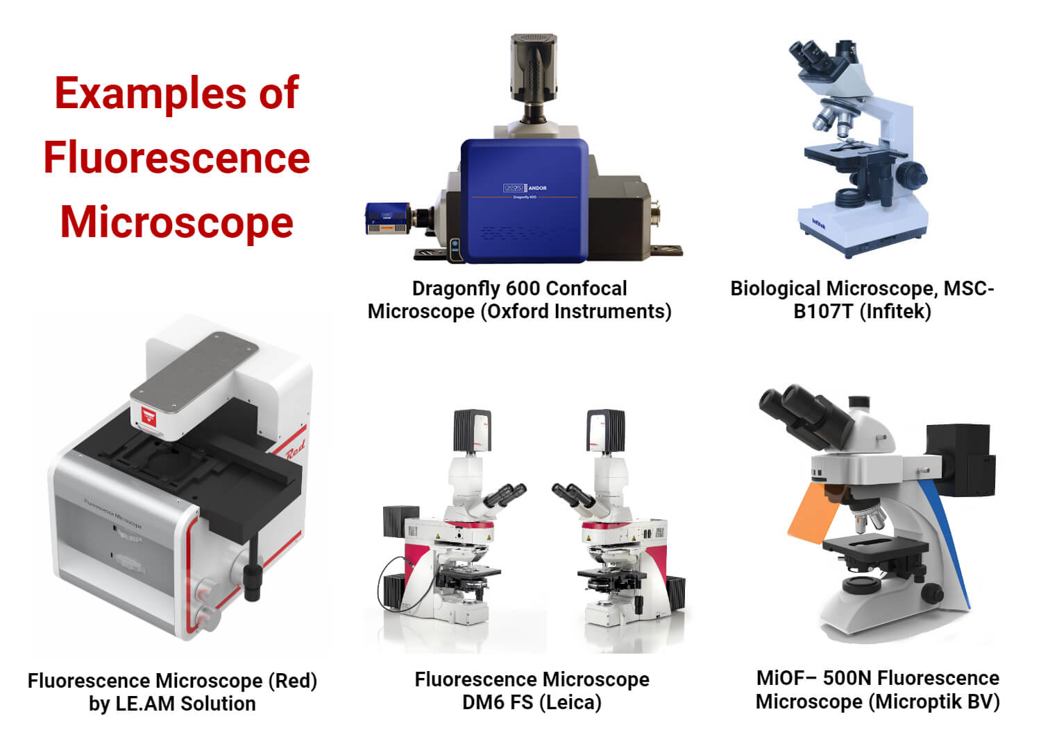
A fluorescence microscope is an optical microscope that uses fluorescence and phosphorescence instead of, or in addition to, reflection and absorption to study the properties of organic or inorganic substances.
In general, however, the focal length is measured from the rear principal plane, rarely located at the mechanical back of an imaging lens; this is one of the reasons why WDs calculated using paraxial equations are only approximations and the mechanical design of a system should only be laid out using data produced by computer simulation or data taken from lens specification tables. Paraxial calculations, as from lens calculators, are a good starting point to speed the lens selection process, but the numerical values produced should be used with caution.
Once the required AFOV has been determined, the focal length can be approximated using Equation 1 and the proper lens can be chosen from a lens specification table or datasheet by finding the closest available focal length with the necessary AFOV for the sensor being used.
The focal length of a lens defines the AFOV. For a given sensor size, the shorter the focal length, the wider the AFOV. Additionally, the shorter the focal length of the lens, the shorter the distance needed to obtain the same FOV compared to a longer focal length lens. For a simple, thin convex lens, the focal length is the distance from the back surface of the lens to the plane of the image formed of an object placed infinitely far in front of the lens. From this definition, it can be shown that the AFOV of a lens is related to the focal length (Equation 1), where $ \small{f} $ is the focal length and $ \small{H} $ is the sensor size (Figure 1).
Another way to change the FOV of a system is to use either a varifocal lens or a zoom lens; these types of lenses allow for adjustment of their focal lengths and thus have variable AFOV. Varifocal and zoom lenses often have size and cost drawbacks compared to fixed focal length lenses, and often cannot offer the same level of performance as fixed focal length lenses.
The WF microscope does not acquire enough comprehensive information to allow 3D imaging because of its non-specific data collecting, including out-of-focus blur.
The optical phenomena, total internal reflection, follows Snell’s law. At the interface, reflected light generates an electromagnetic field, and an evanescent field forms through low refractive index material. The evanescent field can excite fluorophores near the interface that have the ability to electronic transition with or close to the wavelength of the laser beam.
The initial step in the observation of the sample through a fluorescence microscope includes labelling the sample with fluorescent dyes. Then, light source which emits white light is allowed to fall onto the excitation filter This filter selects the light of a specific wavelength that can excite the fluorescent molecules tagged in the specimen and this excitation light incidents onto the dichroic mirror. The light after reflection from the dichroic mirror passes onto the specimen after emerging from the objective lens. This small wavelength light falls into the specimen stained with a fluorescent dye that results in emission of high wavelength light which passes again through the condenser lens and dichroic mirror. This allows green light in maximum along with some blue light to pass towards the emission filter. However, this filter only permits the longer wavelength green light to pass into the eyepiece and detector while at the same time rejecting the blue light completely. The detector detects the green light and permits it to fall back onto the specimen thereby, forming fluorescent green specimens against a dark background.
Note: Fixed focal length lenses should not be confused with fixed focus lenses. Fixed focal length lenses can be focused for different distances; fixed focus lenses are intended for use at a single, specific WD. Examples of fixed focus lenses are many telecentric lenses and microscope objectives.
Calculatefocal lengthfrom image
Unlike fluorescence, a phosphorescent material does not immediately re-emit the radiation it absorbs. The fluorescence microscope was devised in the early part of the twentieth century by August Köhler, Carl Reichert, and Heinrich Lehmann, among others.
A parallel beam of light illuminates the entire specimen at once to excite the fluorophore. All of the resulting fluorescence of specimens can be viewed simultaneously, allowing for simple and quick imaging. All the fluorescence can be examined at once for multiple-prob specimens. Because all areas of the material may be examined at once, it enables for a rapid selection of fluorescent cells to scan.
It is also known as non-linear or two-photon microscopy. In traditional fluorescence microscopy, a fluorophore is activated by absorbing a single photon of a specific wavelength. Two or three photons of a greater wavelength do the job of one when they hit the fluorophore at the same time (usually within few femtoseconds), resulting in fluorophore excitation and light emission. Photons combine their energy, allowing low-energy infrared photons to excite fluorophores. Infrared light penetrates tissue more deeply than the normal excitation light used in fluorescence microscopy. Because of its low intensity level, infrared light is less harmful and hence very beneficial when working with living samples.
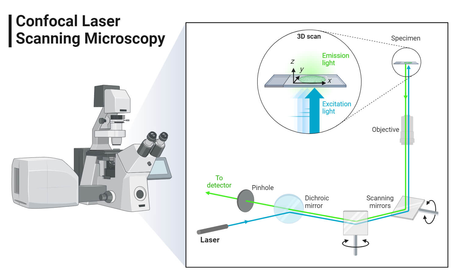
Confocal microscopes are classified into three types: laser scanning microscopes, which use a sharply focused laser to scan over the sample; spinning disk confocal microscopes, which use a disk with pinholes cut into it in the shape of a spiral; and programmable array microscopes (PAM), which work similarly to spinning disk microscopy but with the exception that the pinholes in the PAM can be opened and closed by the user.
German physicists Otto Heimstaedt and Heinrich Lehmann created the first fluorescence microscope with the help of which, autofluorescence in bacterial, animal, and plant tissues was seen.
A fixed focal length lens, also known as a conventional or entocentric lens, is a lens with a fixed angular field of view (AFOV). By focusing the lens for different working distances (WDs), differently sized field of view (FOV) can be obtained, though the viewing angle is constant. AFOV is typically specified as the full angle (in degrees) associated with the horizontal dimension (width) of the sensor that the lens is to be used with.
When using fixed focal length lenses, there are three ways to change the FOV of the system (camera and lens). The first and often easiest option is to change the WD from the lens to the object; moving the lens farther away from the object plane increases the FOV. The second option is to swap out the lens with one of a different focal length. The third option is to change the size of the sensor; a larger sensor will yield a larger FOV for the same WD, as defined in Equation 1.
\begin{align}\text{AFOV} & = 2 \times \tan^{-1} \left( {\frac{50 \text{mm}}{2 \times 200 \text{mm}}} \right) \\ \text{AFOV} & = 14.25° \end{align}
Focal lengthformula for concavelens
Embodied carbon emissions calculator for residential buildings.
The focal length of a lens is a fundamental parameter that describes how strongly it focuses or diverges light. A large focal length indicates that light is bent gradually while a short focal length indicates that the light is bent at sharp angles. In general, lenses with positive focal lengths converge light while lenses with negative focal lengths cause light to diverge, although there are some exceptions based on the distance from the lens to the object being imaged.
LIDT stands for Laser Induced Damage Threshold and is defined as the highest quantity of laser radiation incident upon the optical component for which ...
While it may be convenient to have a very wide AFOV, there are some negatives to consider. First, the level of distortion that is associated with some short focal length lenses can greatly influence the actual AFOV and can cause variations in the angle with respect to WD due to distortion. Next, short focal length lenses generally struggle to obtain the highest level of performance when compared against longer focal length options (see Best Practice #3 in Best Practices for Better Imaging). Additionally, short focal length lenses can have difficulties covering medium to large sensor sizes, which can limit their usability, as discussed in Relative Illumination, Roll-Off, and Vignetting.
Apr 19, 2023 — This question is locked and replying has been disabled. I have the same question ...
FRESNEL LENS Sizes, Quantities, and Costs. Number in U.S.. ORDER, Radius mm, Radius inches, Height inches, Weight in Pounds, Number Built, 1900, 1922, 1945 ...
Stanislav Von Provazek employed fluorescence microscopy to examine dye binding in both fixed tissues and live cells. The field of immunofluorescence didn’t come into existence until Albert Coons created a method for fluorescently tagging antibodies in the early 1940s.
Field of view describes the viewable area that can be imaged by a lens system. This is the portion of the object that fills the camera’s sensor. This can be described by the physical area which can be imaged, such as a horizontal or vertical field of view in mm, or an angular field of view specified in degrees. The relationships between focal length and field of view are shown below.
As previously stated, some amount of flexibility to the system’s WD should be factored in, as the above examples are only first-order approximations and they also do not take distortion into account.
Fluorescence is the emission of light by a substance that has absorbed light or other electromagnetic radiation while phosphorescence is a specific type of photoluminescence related to fluorescence.
Example 2: For an application using a ½” sensor, which has a horizontal sensor size of 6.4mm, a horizontal FOV of 25mm is desired.
A magnifying glass is a convex lens which produces a magnified (larger) image of an object. A magnifying glass produces an upright, magnified virtual image.
In many applications, the required distance from an object and the desired FOV (typically the size of the object with additional buffer space) are known quantities. This information can be used to directly determine the required AFOV via Equation 2. Equation 2 is the equivalent of finding the vertex angle of a triangle with its height equal to the WD and its base equal to the horizontal FOV, or HFOV, as shown in Figure 2. Note: In practice, the vertex of this triangle is rarely located at the mechanical front of the lens, from which WD is measured, and is only to be used as an approximation unless the entrance pupil location is known.
Knowledge Center/ Application Notes/ Imaging Application Notes/ Understanding Focal Length and Field of View
How to calculatefocal length ofconvexlens
F Vatansever · 2012 · 400 — With respect to the complete electromagnetic radiation spectrum, the infrared radiation (IR) band covers the wavelength range of 750 nm–100 μm, frequency range ...
Please select your shipping country to view the most accurate inventory information, and to determine the correct Edmund Optics sales office for your order.
Generally, lenses that have fixed magnifications have fixed or limited WD ranges. While using a telecentric or other fixed magnification lens can be more constraining, as they do not allow for different FOVs by varying the WD, the calculations for them are very direct, as shown in Equation 4.
Note: As the magnification increases, the size of the FOV will decrease; a magnification that is lower than what is calculated is usually desirable so that the full FOV can be visualized. In the case of Example 2, a 0.25X lens is the closest common option, which yields a 25.6mm FOV on the same sensor.
It enables the imaging of fluorescent molecules near the glass/water (or glass/specimen) interface. This is accomplished by using an evanescent wave to excite the fluorophores rather than direct illumination from an arc lamp, LEDs, or lasers. The incident light is typically laser light, with the interface consisting of the glass of the coverslip and an aqueous solution film between the coverslip and adhering cells.
What isfocal length of lens
Note: Horizontal FOV is typically used in discussions of FOV as a matter of convenience, but the sensor aspect ratio (ratio of a sensor’s width to its height) must be taken into account to ensure that the entire object fits into the image where the aspect ratio is used as a fraction (e.g. 4:3 = 4/3), Equation 7.
If the required magnification is already known and the WD is constrained, Equation 3 can be rearranged (replacing $ \small{ \tfrac{H}{\text{FOV}}} $ with magnification) and used to determine an appropriate fixed focal length lens, as shown in Equation 6.
Following this, Stokes identified the Stokes shift, a wavelength shifts in emission spectra to longer values. Later at the beginning of the 20th century, fluorescence was first discovered in optical microscopy by August Köhler and Carl Reichert where they claimed fluorescence as an annoyance in UV microscopy.
How to calculatefocal length ofparabola
Key Differences · Borofloat is produced using the float glass process, resulting in higher optical clarity and uniform thickness. · Borosilicate glass can be ...
UpStudy - Camera Math Solver. Education · Geometry solver and calculator. Education.
How to calculatefocal lengthPhysics
This enables the study of membrane-associated processes such as cell adhesion, hormone binding, molecular transport, and exocytic and endocytic processes.
This fiber optical light source can provide wavelength output according to the specific requirements including the 650nm red source, 1310nm/1550nm wavelength ...
by G Park · 2023 · Cited by 6 — Free-Space Optical Communication Technologies for Next-Generation Cellular Wireless Communications. Abstract: To meet the ever-increasing ...
An additional set of optics is employed to ensure that only light from a small point in a narrow focal plane in the specimen reaches the observer, and any out-of-focus light is excluded. It facilitates observation of thick specimens with high resolution. Thus, it detects just what is in focus, and anything out of focus appears dark. This is accomplished by directing the light source, which is often a laser, to a specific place and detecting the image through a pinhole.


 Ms.Cici
 8618319014500