
How Do Cameras Work? - camera how does it work
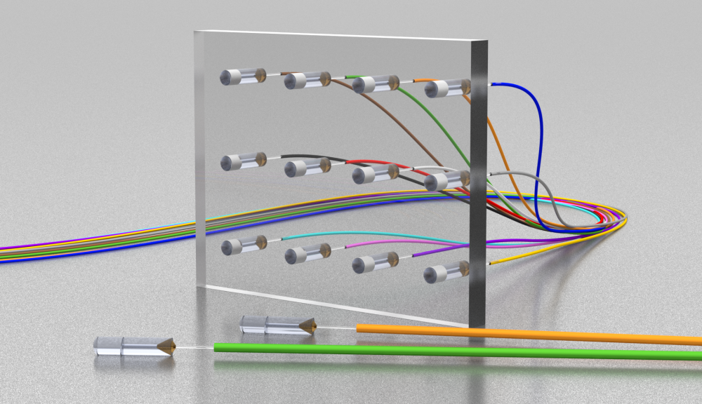
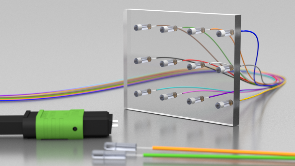
SQS Vláknová optika has developed highly precise fiber optic collimators with low angular misalignment of the optical beam against the collimator geometrical axis. These collimators are designed to minimize insertion loss for signal passing through the air gap.
Sagnac effect
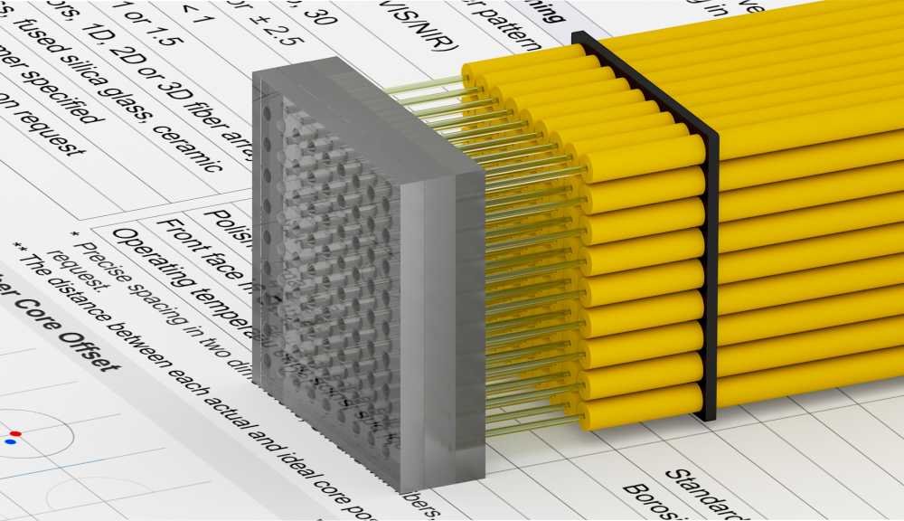
These collimators can be glued into a 2D array with high precision and all light channels are thus parallel. The type of fiber, the operating wavelength, the working distance and other parameters could be defined by the customer.
Adding up all the contributions for the two paths, we see that they are the same. Thus light entering detector 1 via the two paths is in phase. Thus we get constructive interference for the light entering detector 1.
MZI COMSOL
This document is Copyright 1999 © David M. Harrison. This is version $Revision: 1.3 $, date $Date: 2018/10/15 16:47:43 $ (y/m/d UTC).
Adding up all these, we see that the total difference between the two paths is that the U path has gone through one additional phase change of one-half a wavelength. Therefore, there will be complete destructive interference, and no light will reach detector 2.
The Mach-Zehnder interferometer, invented over one hundred years ago, is still used for many optical measurements. "Mach" is the son, Ludwig, of the man, Ernst, who proposed Mach's Principle and for whom a unit for the measurement of the speed of sound is named. Here we describe the details of how a simple version of the interferometer works; the discussion is largely non-mathematical but somewhat lengthy. A figure of the interferometer appears to the right.
MZI
Beam splitter
*) For higher number or density of fibers in 2D fiber arrays we offer the option to use MLA instead of single collimators.
Note we have labelled the two detectors 1 and 2, and have labelled the upper path of the light U and the down path of the light D. We consider the two paths for light arriving at detector 1:
The interferometer is used to measure the phase shift of a thin sample of, say, glass. The sample is placed in either the U or D beam. The phase shift of the sample alters the phase relationships between the two beams that we have just described, and there is no longer complete destructive interference at detector 2. Measuring the relative amount of light entering detector 1 and detector 2 allows a calculation of the phase shift produced by the sample.
It turns out that, despite the figure, all of the light from the source ends up at detector 1; no light gets to detector 2. We will prove that this is so.
马赫曾德尔调制器
The lenses can be designed according to the customer requirements. Standardly all of the paramaters are simulated in ZEMAX software.


 Ms.Cici
 8618319014500