
Hidden Strobe - strobo lights
Microscopy has applications in the forensic sciences.[64] The microscope can detect, resolve and image the smallest items of evidence, often without any alteration or destruction. The microscope is used to identify and compare fibers, hairs, soils, and dust...etc.
A multitude of super-resolution microscopy techniques have been developed in recent times which circumvent the diffraction limit.
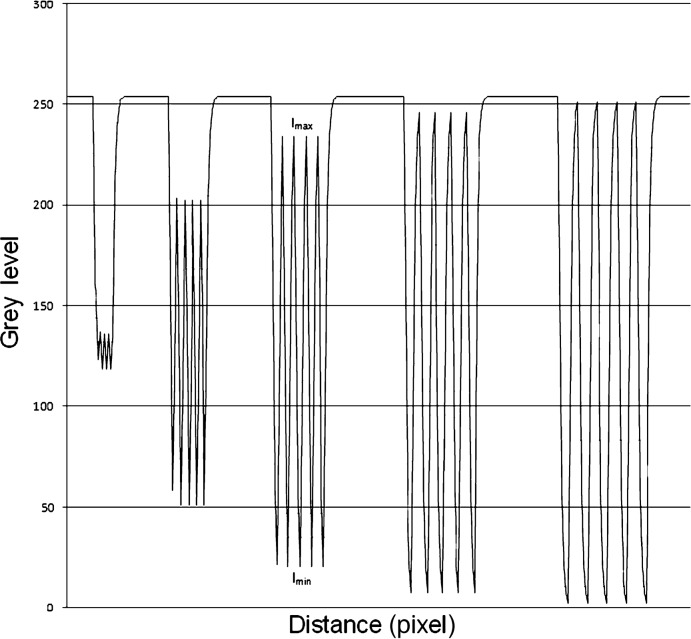
where Imax denotes the maximum intensity or grey level found in region of interest gmax and Imin denotes the minimum intensity or grey level gmin found in the region of interest.
The filters were realized in image processing software programmed in Borland C-Builder 6.0 (Borland GmbH, Langen, Germany) according to the filter algorithms found in the literature.5,13,14 For this study we chose the most common noise-suppression filters5,6 that are popular in current imaging software: two arithmetic mean filters with kernel sizes of 3 × 3 pixels and 5 × 5 pixels (mean 3 × 3, mean 5 × 5), two median filters with kernel sizes of 3 × 3 pixels and 5 × 5 pixels (median 3 × 3, median 5 × 5) and two Gaussian filters with kernel sizes of 3 × 3 pixels and 5 × 5 pixels (Gauss 3 × 3/0.4, Gauss 5 × 5/0.4) and an SD of 0.4. Test images were processed with each filter.
The creation of accurate micrographs requires a microscopical technique using a monocular eyepiece. It is essential that both eyes are open and that the eye that is not observing down the microscope is instead concentrated on a sheet of paper on the bench besides the microscope. With practice, and without moving the head or eyes, it is possible to accurately trace the observed shapes by simultaneously "seeing" the pencil point in the microscopical image.[citation needed]
Modulation transferfunctionRadiology
Laser microscopy is a rapidly growing field that uses laser illumination sources in various forms of microscopy.[44] For instance, laser microscopy focused on biological applications uses ultrashort pulse lasers, in a number of techniques labeled as nonlinear microscopy, saturation microscopy, and two-photon excitation microscopy.[45]
Highly efficient fluorescent proteins such as the green fluorescent protein (GFP) have been developed using the molecular biology technique of gene fusion, a process that links the expression of the fluorescent compound to that of the target protein. This combined fluorescent protein is, in general, non-toxic to the organism and rarely interferes with the function of the protein under study. Genetically modified cells or organisms directly express the fluorescently tagged proteins, which enables the study of the function of the original protein in vivo.
The field of microscopy (optical microscopy) dates back to at least the 17th-century. Earlier microscopes, single lens magnifying glasses with limited magnification, date at least as far back as the wide spread use of lenses in eyeglasses in the 13th century[2] but more advanced compound microscopes first appeared in Europe around 1620[3][4] The earliest practitioners of microscopy include Galileo Galilei, who found in 1610 that he could close focus his telescope to view small objects close up[5][6] and Cornelis Drebbel, who may have invented the compound microscope around 1620.[7][8] Antonie van Leeuwenhoek developed a very high magnification simple microscope in the 1670s and is often considered to be the first acknowledged microscopist and microbiologist.[9][10]
The modulation transfer function (MTF) is a graphical description of the spatial resolution characteristics of an imaging system or its individual components. It is generally useful for separating individual causes of image degradation. Another related term is the contrast transfer function (CTF). MTF describes the response of an optical system to an image decomposed into sine waves and CTF describes the response of an optical system to an image decomposed into square waves (for example, an image of line pairs).1,2 The term MTF will be used in this article. The signal-to-noise ratio (SNR) generally refers to the dimensionless ratio of the signal power to the noise power contained in a signal. It parameterizes the performance of signal processing systems when noise is contained in a recording (or an image).3,4
It is always less tiring to observe with the microscope focused so that the image is seen at infinity and with both eyes open at all times. [citation needed]
Introducing our Optics Silicon Hyper Hemherical Lens! With precise specifications and a Silicon substrate, this lens is perfect for infrared applications.
The Gaussian filter with a 5 × 5 kernel size caused the highest noise suppression (SNR increased from 2.22, measured in the synthetic image, to 11.31 in the filtered image). The smallest noise reduction was found with the 3 × 3 median filter. The application of the median filters resulted in no changes in MTF at the different resolutions but did result in the deletion of smaller structures. The 5 × 5 Gaussian filter and the 5 × 5 arithmetic mean filter showed the strongest changes of MTF.
P A ∝ α ∗ Γ ∗ ( ( 1 − η f l ) ∗ E g + ( E l a s e r − E g ) ) {\displaystyle PA\propto \alpha *\Gamma *((1-\eta _{fl})*E_{g}+(E_{laser}-E_{g}))}
Superior and much more expensive is the use of interference contrast. Differences in optical density will show up as differences in relief. A nucleus within a cell will actually show up as a globule in the most often used differential interference contrast system according to Georges Nomarski. However, it has to be kept in mind that this is an optical effect, and the relief does not necessarily resemble the true shape. Contrast is very good and the condenser aperture can be used fully open, thereby reducing the depth of field and maximizing resolution.
Where denotes the mean value of some measure of signal strength the grey level in this case, defined as mean grey level g in the following, is the SD of the noise, or an estimate thereof the grey level SD defined as g.
Aims & Scope. Optics & Laser Technology aims to provide a vehicle for the publication of a broad range of high quality research and review papers in those ...
More sophisticated techniques will show proportional differences in optical density. Phase contrast is a widely used technique that shows differences in refractive index as difference in contrast. It was developed by the Dutch physicist Frits Zernike in the 1930s (for which he was awarded the Nobel Prize in 1953). The nucleus in a cell for example will show up darkly against the surrounding cytoplasm. Contrast is excellent; however it is not for use with thick objects. Frequently, a halo is formed even around small objects, which obscures detail. The system consists of a circular annulus in the condenser, which produces a cone of light. This cone is superimposed on a similar sized ring within the phase-objective. Every objective has a different size ring, so for every objective another condenser setting has to be chosen. The ring in the objective has special optical properties: it, first of all, reduces the direct light in intensity, but more importantly, it creates an artificial phase difference of about a quarter wavelength. As the physical properties of this direct light have changed, interference with the diffracted light occurs, resulting in the phase contrast image. One disadvantage of phase-contrast microscopy is halo formation (halo-light ring).
Fluorescence microscopy is a powerful technique to show specifically labeled structures within a complex environment and to provide three-dimensional information of biological structures. However, this information is blurred by the fact that, upon illumination, all fluorescently labeled structures emit light, irrespective of whether they are in focus or not. So an image of a certain structure is always blurred by the contribution of light from structures that are out of focus. This phenomenon results in a loss of contrast especially when using objectives with a high resolving power, typically oil immersion objectives with a high numerical aperture.
The authors would like to express their gratitude for constructive comments and suggestions by the reviewers. There are no potential conflicts of interest or sources of financial support.
Modulation transferfunctionformula
IR lens, 15° FOV, 41.3mm (T197914) The 15° lens is a popular lens accessory and provides 1.7× magnification compared to the standard lens.
Here hg denotes the number of pixels with grey level g and M denotes the total number of pixels in the image. The mean grey level g can be calculated using the grey level density function Pg Equation 3 where L denotes the number of grey levels present in the image.
You can find Doosan's IR materials such as yearly, quarterly management performance reports here.
Using a plane of light formed by focusing light through a cylindrical lens at a narrow angle or by scanning a line of light in a plane perpendicular to the axis of objective, high resolution optical sections can be taken.[22][23][24] Single plane illumination, or light sheet illumination, is also accomplished using beam shaping techniques incorporating multiple-prism beam expanders.[25][26] The images are captured by CCDs. These variants allow very fast and high signal to noise ratio image capture.
Official websites use .gov A .gov website belongs to an official government organization in the United States.
A microscopy technique relying on the photoacoustic effect,[61] i.e. the generation of (ultra)sound caused by light absorption. A focused and intensity modulated laser beam is raster scanned over a sample. The generated (ultra)sound is detected via an ultrasound transducer. Commonly piezoelectric ultrasound transducers are employed.[62]
The system consists of a special prism (Nomarski prism, Wollaston prism) in the condenser that splits light in an ordinary and an extraordinary beam. The spatial difference between the two beams is minimal (less than the maximum resolution of the objective). After passage through the specimen, the beams are reunited by a similar prism in the objective.
MTFimage quality
Image quality can be influenced by many factors. As demonstrated in this study, the use of noise filters can change SNR and MTF. The MTF describes how well an imaging system performs in depiction of fine structures with minimal blur. Image quality can be improved with increased signal strength and reduced noise levels as expressed in the SNR. Imaging theory decrees that the highest SNR will result in higher image quality and more accurate images.4 This article demonstrates that the simple application of small convolution filters can improve SNR significantly (Table 1). However, the use of noise filters led to a change of the MTF. Contrast and resolution changes of the filters can be directly read from the graphs because the MTF describes the ability of a system to depict small structures. The fitted functions follow the form y = A*ebx. Thus, the effects of the filters on blur can be construed directly. The filters resulting in a graph of the form y = 1 (like the unprocessed images) showed no change of resolution (besides known side effects17 and deletion of the bar’s edge pixels). The initial value of the function was A = 1 in this case. The term bx degraded to 0 (Appendix). This means MTF did not change for any resolution. The strongest MTF changes were found for the 5 × 5 arithmetic mean filter. The found graph has the expression y = 0.68e−0.76x. This means changes in contrast are even found for larger stripe patterns (A = 0.68). The graph y = 1.015e−0.98x calculated for the 5 × 5 Gaussian filter shows that the filter will preserve contrast better for larger stripe patterns. However, a stronger decrease in contrast (and an increase in blur) will result for higher spatial resolutions, as denoted by a value of b = −0.98. The linear filters with the 3 × 3 convolution kernels performed between the median filters and the linear filters with bigger kernels.
Optical or light microscopy involves passing visible light transmitted through or reflected from the sample through a single lens or multiple lenses to allow a magnified view of the sample.[11] The resulting image can be detected directly by the eye, imaged on a photographic plate, or captured digitally. The single lens with its attachments, or the system of lenses and imaging equipment, along with the appropriate lighting equipment, sample stage, and support, makes up the basic light microscope. The most recent development is the digital microscope, which uses a CCD camera to focus on the exhibit of interest. The image is shown on a computer screen, so eye-pieces are unnecessary.[12]
Though less common, X-ray microscopy has also been developed since the late 1940s. The resolution of X-ray microscopy lies between that of light microscopy and electron microscopy.
Bright field microscopy is the simplest of all the light microscopy techniques. Sample illumination is via transmitted white light, i.e. illuminated from below and observed from above. Limitations include low contrast of most biological samples and low apparent resolution due to the blur of out-of-focus material. The simplicity of the technique and the minimal sample preparation required are significant advantages.[citation needed]
Growth of protein crystals results in both protein and salt crystals. Both are colorless and microscopic. Recovery of the protein crystals requires imaging which can be done by the intrinsic fluorescence of the protein or by using transmission microscopy. Both methods require an ultraviolet microscope as proteins absorbs light at 280 nm. Protein will also fluorescence at approximately 353 nm when excited with 280 nm light.[18]
Modulation transferfunctionimage processing
where μ denotes the mean value of some measure of signal strength (the grey level in this case) and σ is the SD of the noise or an estimate thereof (the grey level's SD). To calculate SNR, mean grey values in four test images containing defined increasing amounts of Gaussian noise (SD = 10; SD = 20; SD = 30; SD = 40, respectively) were measured and documented using an Excel 2007 spreadsheet (Microsoft, Redmond, WA). SDs were also measured. SNR was plotted for all SDs. The modulation transfer function m can be defined as:
Rheinberg illumination is a variant of dark field illumination in which transparent, colored filters are inserted just before the condenser so that light rays at high aperture are differently colored than those at low aperture (i.e., the background to the specimen may be blue while the object appears self-luminous red). Other color combinations are possible, but their effectiveness is quite variable.[17]
Where n is the additive noise.[32] Knowing this point spread function[33] means that it is possible to reverse this process to a certain extent by computer-based methods commonly known as deconvolution microscopy.[34] There are various algorithms available for 2D or 3D deconvolution. They can be roughly classified in nonrestorative and restorative methods. While the nonrestorative methods can improve contrast by removing out-of-focus light from focal planes, only the restorative methods can actually reassign light to its proper place of origin. Processing fluorescent images in this manner can be an advantage over directly acquiring images without out-of-focus light, such as images from confocal microscopy, because light signals otherwise eliminated become useful information. For 3D deconvolution, one typically provides a series of images taken from different focal planes (called a Z-stack) plus the knowledge of the PSF, which can be derived either experimentally or theoretically from knowing all contributing parameters of the microscope.
The antibodies can be tailor-made for a chemical compound. For example, one strategy often in use is the artificial production of proteins, based on the genetic code (DNA). These proteins can then be used to immunize rabbits, forming antibodies which bind to the protein. The antibodies are then coupled chemically to a fluorophore and used to trace the proteins in the cells under study.
Electron microscopes equipped for X-ray spectroscopy can provide qualitative and quantitative elemental analysis. This type of electron microscope, also known as analytical electron microscope, can be a very powerful tool for investigation of nanomaterials.[39]
This is a sub-diffraction technique. Examples of scanning probe microscopes are the atomic force microscope (AFM), the scanning tunneling microscope, the photonic force microscope and the recurrence tracking microscope. All such methods use the physical contact of a solid probe tip to scan the surface of an object, which is supposed to be almost flat.
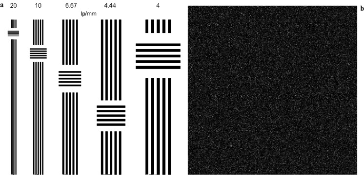
(a) Stripe patterns with defined amount of line pairs per mm and (b) test image with a uniform grey level of 20 and a defined amount of Gaussian noise (σ = 40)
Live cells in particular generally lack sufficient contrast to be studied successfully, since the internal structures of the cell are colorless and transparent. The most common way to increase contrast is to stain the structures with selective dyes, but this often involves killing and fixing the sample.[15] Staining may also introduce artifacts, which are apparent structural details that are caused by the processing of the specimen and are thus not features of the specimen. In general, these techniques make use of differences in the refractive index of cell structures. Bright-field microscopy is comparable to looking through a glass window: one sees not the glass but merely the dirt on the glass. There is a difference, as glass is a denser material, and this creates a difference in phase of the light passing through. The human eye is not sensitive to this difference in phase, but clever optical solutions have been devised to change this difference in phase into a difference in amplitude (light intensity).[citation needed]
The term infrared microscopy refers to microscopy performed at infrared wavelengths. In the typical instrument configuration, a Fourier Transform Infrared Spectrometer (FTIR) is combined with an optical microscope and an infrared detector. The infrared detector can be a single point detector, a linear array or a 2D focal plane array. FTIR provides the ability to perform chemical analysis via infrared spectroscopy and the microscope and point or array detector enable this chemical analysis to be spatially resolved, i.e. performed at different regions of the sample. As such, the technique is also called infrared microspectroscopy[40][41] An alternative architecture called Laser Direct Infrared (LDIR) Imaging involves the combination of a tuneable infrared light source and single point detector on a flying objective. This technique is frequently used for infrared chemical imaging, where the image contrast is determined by the response of individual sample regions to particular IR wavelengths selected by the user, usually specific IR absorption bands and associated molecular resonances. A key limitation of conventional infrared microspectroscopy is that the spatial resolution is diffraction-limited. Specifically the spatial resolution is limited to a figure related to the wavelength of the light. For practical IR microscopes, the spatial resolution is limited to 1-3x the wavelength, depending on the specific technique and instrument used. For mid-IR wavelengths, this sets a practical spatial resolution limit of ~3-30 μm.
Nov 23, 2020 — IR will pass through many plastics but there are two factors that could impact your printing. First, pigmented plastics vs dye based color - the ...
Optical microscopy and electron microscopy involve the diffraction, reflection, or refraction of electromagnetic radiation/electron beams interacting with the specimen, and the collection of the scattered radiation or another signal in order to create an image. This process may be carried out by wide-field irradiation of the sample (for example standard light microscopy and transmission electron microscopy) or by scanning a fine beam over the sample (for example confocal laser scanning microscopy and scanning electron microscopy). Scanning probe microscopy involves the interaction of a scanning probe with the surface of the object of interest. The development of microscopy revolutionized biology, gave rise to the field of histology and so remains an essential technique in the life and physical sciences. X-ray microscopy is three-dimensional and non-destructive, allowing for repeated imaging of the same sample for in situ or 4D studies, and providing the ability to "see inside" the sample being studied before sacrificing it to higher resolution techniques. A 3D X-ray microscope uses the technique of computed tomography (microCT), rotating the sample 360 degrees and reconstructing the images. CT is typically carried out with a flat panel display. A 3D X-ray microscope employs a range of objectives, e.g., from 4X to 40X, and can also include a flat panel.
Stripe patterns after application of digital filters. The results of filters with 3×3 kernels are shown in the upper row with the larger 5×5 kernels below
Secure .gov websites use HTTPS A lock ( Lock Locked padlock icon ) or https:// means you've safely connected to the .gov website. Share sensitive information only on official, secure websites.
Ultraviolet microscopes have two main purposes. The first is to use the shorter wavelength of ultraviolet electromagnetic energy to improve the image resolution beyond that of the diffraction limit of standard optical microscopes. This technique is used for non-destructive inspection of devices with very small features such as those found in modern semiconductors. The second application for UV microscopes is contrast enhancement where the response of individual samples is enhanced, relative to their surrounding, due to the interaction of light with the molecules within the sample itself. One example is in the growth of protein crystals. Protein crystals are formed in salt solutions. As salt and protein crystals are both formed in the growth process, and both are commonly transparent to the human eye, they cannot be differentiated with a standard optical microscope. As the tryptophan of protein absorbs light at 280 nm, imaging with a UV microscope with 280 nm bandpass filters makes it simple to differentiate between the two types of crystals. The protein crystals appear dark while the salt crystals are transparent.
This method is of critical importance in the modern life sciences, as it can be extremely sensitive, allowing the detection of single molecules. Many fluorescent dyes can be used to stain structures or chemical compounds. One powerful method is the combination of antibodies coupled to a fluorophore as in immunostaining. Examples of commonly used fluorophores are fluorescein or rhodamine.
However, blurring is not caused by random processes, such as light scattering, but can be well defined by the optical properties of the image formation in the microscope imaging system. If one considers a small fluorescent light source (essentially a bright spot), light coming from this spot spreads out further from our perspective as the spot becomes more out of focus. Under ideal conditions, this produces an "hourglass" shape of this point source in the third (axial) dimension. This shape is called the point spread function (PSF) of the microscope imaging system. Since any fluorescence image is made up of a large number of such small fluorescent light sources, the image is said to be "convolved by the point spread function". The mathematically modeled PSF of a terahertz laser pulsed imaging system is shown on the right.
Light microscopes are the most use in forensics, using photons to form images, microscopes which are most applicable for examining forensic specimens are as follows:[65]
Note: In cases where the optical design of a microscope produces an appreciable lateral separation of the two beams we have the case of classical interference microscopy, which does not result in relief images, but can nevertheless be used for the quantitative determination of mass-thicknesses of microscopic objects.
Amateur Microscopy is the investigation and observation of biological and non-biological specimens for recreational purposes. Collectors of minerals, insects, seashells, and plants may use microscopes as tools to uncover features that help them classify their collected items. Other amateurs may be interested in observing the life found in pond water and of other samples. Microscopes may also prove useful for the water quality assessment for people that keep a home aquarium. Photographic documentation and drawing of the microscopic images are additional pleasures. There are competitions for photomicrograph art. Participants of this pastime may use commercially prepared microscopic slides or prepare their own slides.
Wide-field multiphoton microscopy[27][28][29][30] refers to an optical non-linear imaging technique in which a large area of the object is illuminated and imaged without the need for scanning. High intensities are required to induce non-linear optical processes such as two-photon fluorescence or second harmonic generation. In scanning multiphoton microscopes the high intensities are achieved by tightly focusing the light, and the image is obtained by beam scanning. In wide-field multiphoton microscopy the high intensities are best achieved using an optically amplified pulsed laser source to attain a large field of view (~100 μm).[27][28][29] The image in this case is obtained as a single frame with a CCD camera without the need of scanning, making the technique particularly useful to visualize dynamic processes simultaneously across the object of interest. With wide-field multiphoton microscopy the frame rate can be increased up to a 1000-fold compared to multiphoton scanning microscopy.[28] In scattering tissue, however, image quality rapidly degrades with increasing depth.
The Gaussian filter with a 5 × 5 kernel produced the highest noise suppression based on SNR. The SNR increased from 2.22 in the synthetic image (with Gaussian noise amount of SD = 10) to 11.31 in the filtered image (for a synthetic noise amount of SD = 10). The 5 × 5 arithmetic mean filter and the 5 × 5 median filter followed closely (Table 1). The smallest noise reduction was found using the 3 × 3 median filter (Table 1). The median filters showed no changes in MTF at the different resolutions (the approximated graph was y = 1). Application of the 5 × 5 Gaussian filter and the 5 × 5 arithmetic mean filter resulted in the strongest changes in MTF (Figure 3). Approximated graphs were y = 0.68e−0.76x for the 5 × 5 arithmetic mean filter and y = 1.015e−0.98x for the 5 × 5 Gaussian filter. The graph found for the 3 × 3 Gaussian filter and the 3 × 3 arithmetic mean filter was y = 1.277e−0.76x (Table 2). With an unchanged MTF the application of median filters resulted in a deletion of small structures (Figure 4). Single lines on the outside of the 20 lp mm–1 stripe pattern were deleted and the overall size of all stripes was reduced.
When certain compounds are illuminated with high energy light, they emit light of a lower frequency. This effect is known as fluorescence. Often specimens show their characteristic autofluorescence image, based on their chemical makeup.
The image contrast is related to the sample's absorption coefficient α {\displaystyle \alpha } . This is in contrast to bright or dark field microscopy, where the image contrast is due to transmittance or scattering. In principle, the contrast of fluorescence microscopy is proportional to the sample's absorption too. However, in fluorescence microscopy the fluorescence quantum yield η f l {\displaystyle \eta _{fl}} needs to be unequal to zero in order that a signal can be detected. In photoacoustic microscopy, however, every absorbing substance gives a photoacoustic signal P A {\displaystyle PA} which is proportional to
To block the excitation light from reaching the observer or the detector, filter sets of high quality are needed. These typically consist of an excitation filter selecting the range of excitation wavelengths, a dichroic mirror, and an emission filter blocking the excitation light. Most fluorescence microscopes are operated in the Epi-illumination mode (illumination and detection from one side of the sample) to further decrease the amount of excitation light entering the detector.
Although MTF can be calculated in different ways, the approach presented here is straightforward and can be easily replicated. Experimentally determined MTFs can be reasonably modelled by simple analytical approximations. The earliest of these to be used were simple exponential.15 Advantages of exponential fits are that they are easily calculated using least square fit methods16 and their direct interpretation. Exponentially fitted graphs relate relatively accurately to the sampled MTF in the evaluated range and the performance of the filters used towards blur can be read directly from the resulting terms. However the fits are not accurate to the sampled data at the end points of the approximated MTF curves.15 Therefore, combinations of Gaussian and exponential functions or other fitting methods have been introduced to model MTF curves.15,18 The exponential approximation of MTF allows good estimates of the resolution changes caused by digital filters.
Modulation transferfunctionin Ophthalmology
An additional technique using interference is interference reflection microscopy (also known as reflected interference contrast, or RIC). It relies on cell adhesion to the slide to produce an interference signal. If there is no cell attached to the glass, there will be no interference.
DHM can operate both in reflection and transmission mode. In reflection mode, the phase shift image provides a relative distance measurement and thus represents a topography map of the reflecting surface. In transmission mode, the phase shift image provides a label-free quantitative measurement of the optical thickness of the specimen. Phase shift images of biological cells are very similar to images of stained cells and have successfully been analyzed by high content analysis software.
2.00 Magnifying Lens · Features · Specifications · Resources. Features. Details. If you wear bi-focals or ...
Low-pass filters are often used to remove noise from images obtained using digital sensors. They can be described as image algorithms that remove sudden discontinuities of grey levels in small local areas of the image. These low-pass filters, generally designated as linear filters, use convolution to compute images with a lower amount of noise. They are generally realized as spatial smoothing using convolution of the image and a smoothing kernel.5 Low-pass filters attenuate high frequencies, while low frequencies remain unchanged. This means that high spatial frequency components are removed from an image resulting in a smoother image in the spatial domain. Linear low-pass filters can be realized as an arithmetic mean filter, which smoothes an image by averaging all pixels within the convolution kernel and equal contribution of all pixels within that kernel. Another approach for a low-pass filter is the Gaussian filter. This filter works in a similar way to an arithmetic mean filter. The degree of smoothing is determined by the standard deviation (SD) of the Gaussian, which is used to compute the entries of the convolution kernel. The effect of a Gaussian filter is similar to that of a pyramid filter5 with more contribution of central pixels because of weighting through the entries of the convolution kernel. With a larger SD, Gaussian filters require larger convolution kernels to be represented accurately. This can lead to inadequate blurring while using larger convolution masks. Most smoothing filters based on convolution act as low-pass frequency filters. Another effective approach to noise reduction are rank order statistic filters usually referred to as non-linear filters, of which the median filter is one of the most commonly used.5,6 Non-linear filters are generally based on sorting algorithms in an attempt to determine median values that minimize local grey variance.5-7 A median filter removes drop-out noise more efficiently and preserves the edges and small details of an image better than an arithmetic mean filter. The purpose of a median filter is to eliminate intensity spikes, speckles or salt and pepper noise. Broadly, rank order filters are more effective for overcoming impulse noise.5-7
Other articles where dispersion relation is discussed: radiation: Dispersion: …with frequency is called a dispersion relation. For visible light the index ...
The aim of this study was to illustrate the influence of digital filters on the signal-to-noise ratio (SNR) and modulation transfer function (MTF) of digital images. The article will address image pre-processing that may be beneficial for the production of clinically useful digital radiographs with lower radiation dose.
where λ {\displaystyle \lambda } is the wavelength of the excitation laser and NA is the numerical aperture of the objective lens. The Abbe diffraction limit holds if the incoming wave front is parallel. In reality, however, the laser beam profile is Gaussian. Therefore, in order to the calculate the achievable resolution, formulas for truncated Gaussian beams have to be used.[63]
Dr Brüllmann, Department of Oral Surgery, University Medical Center of the Johannes Gutenberg University Mainz, Augustusplatz 2, 55131 Mainz, Germany. E-mail: bruellmd@mail.uni-mainz.de
Digital pathology is an image-based information environment enabled by computer technology that allows for the management of information generated from a digital slide. Digital pathology is enabled in part by virtual microscopy, which is the practice of converting glass slides into digital slides that can be viewed, managed, and analyzed.
This diversity of the types of microscopes in forensic applications comes mainly from their magnification ranges, which are (1- 1200X), (50 -30,000X) and (500- 250,000X) for the optical microscopy, SEM and TEM respectively.[65]
Until the invention of sub-diffraction microscopy, the wavelength of the light limited the resolution of traditional microscopy to around 0.2 micrometers. In order to gain higher resolution, the use of an electron beam with a far smaller wavelength is used in electron microscopes.
Here Γ {\displaystyle \Gamma } is the Grüneisen coefficient, E l a s e r {\displaystyle E_{laser}} is the laser's photon energy and E g {\displaystyle E_{g}} is the sample's band gap energy. Therefore, photoacoustic microscopy seems well suited as a complementary technique to fluorescence microscopy, as a high fluorescence quantum yield leads to high fluorescence signals and a low fluorescence quantum yield leads to high photoacoustic signals.
Here A denotes the initial value at position x0, while y denotes the value of the function found in position x and eb describes the growth of the function, which means a decrease for negative values of b.
Artificial stripe patterns were created with increasing stripe sizes to create defined test patterns for resolutions tests and MTF (Figure 1). The width of the stripes ranged from 1 pixel to 5 pixels (between 20 line pairs per millimetre and 4 line pairs per millimetre calculated upon the defined pixel size given in the synthetic image).
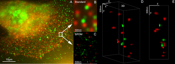
This is mostly achieved by imaging a sufficiently static sample multiple times and either modifying the excitation light or observing stochastic changes in the image. The deconvolution methods described in the previous section, which removes the PSF induced blur and assigns a mathematically 'correct' origin of light, are used, albeit with slightly different understanding of what the value of a pixel mean. Assuming most of the time, one single fluorophore contributes to one single blob on one single taken image, the blobs in the images can be replaced with their calculated position, vastly improving resolution to well below the diffraction limit.
Flowchart of common image processing steps in a system using a charge-coupled device sensor. The rounded rectangles in grey denote optional measures that can be used in the pre-processing steps to improve image quality before displaying it
IR versions of sub-diffraction microscopy also exist.[40][41] These include IR Near-field scanning optical microscope (NSOM),[42] photothermal microspectroscopy and atomic force microscope based infrared spectroscopy (AFM-IR), as well as scattering-type Scanning Near-field Optical Microscopy (s-SNOM)[43] & nano-FTIR that provide nanoscale spatial resolution at IR wavelengths.
High-intensity, short-pulse laboratory x-ray lasers have been under development for several years. When this technology comes to fruition, it will be possible to obtain magnified three-dimensional images of elementary biological structures in the living state at a precisely defined instant. For optimum contrast between water and protein and for best sensitivity and resolution, the laser should be tuned near the nitrogen line at about 0.3 nanometers. Resolution will be limited mainly by the hydrodynamic expansion that occurs while the necessary number of photons is being registered.[46] Thus, while the specimen is destroyed by the exposure, its configuration can be captured before it explodes.[47][48][49][50][51][52][excessive citations]
In conclusion, the simple application of digital filters can improve the SNR of a digital sensor tremendously (Table 1; Figure 3). However, the MTF can be altered in an unfavourable manner, mainly by linear filters with larger convolution kernels (Table 2; Figure 4). Owing to a lack of any standard when using pre-processing, which can change resolution characteristics and image quality, imaging systems can lead to unknown loss of information.
A two-photon microscope is also a laser-scanning microscope, but instead of UV, blue or green laser light, a pulsed infrared laser is used for excitation. Only in the tiny focus of the laser is the intensity high enough to generate fluorescence by two-photon excitation, which means that no out-of-focus fluorescence is generated, and no pinhole is necessary to clean up the image.[19] This allows imaging deep in scattering tissue, where a confocal microscope would not be able to collect photons efficiently.[20] Two-photon microscopes with wide-field detection are frequently used for functional imaging, e.g. calcium imaging, in brain tissue.[21] They are marketed as Multiphoton microscopes by several companies, although the gains of using 3-photon instead of 2-photon excitation are marginal.
To improve specimen contrast or highlight structures in a sample, special techniques must be used. A huge selection of microscopy techniques are available to increase contrast or label a sample.
In digital holographic microscopy (DHM), interfering wave fronts from a coherent (monochromatic) light-source are recorded on a sensor. The image is digitally reconstructed by a computer from the recorded hologram. Besides the ordinary bright field image, a phase shift image is created.
A subclass of confocal microscopes are spinning disc microscopes which are able to scan multiple points simultaneously across the sample. A corresponding disc with pinholes rejects out-of-focus light. The light detector in a spinning disc microscope is a digital camera, typically EM-CCD or sCMOS.
Dark field microscopy is a technique for improving the contrast of unstained, transparent specimens.[16] Dark field illumination uses a carefully aligned light source to minimize the quantity of directly transmitted (unscattered) light entering the image plane, collecting only the light scattered by the sample. Dark field can dramatically improve image contrast – especially of transparent objects – while requiring little equipment setup or sample preparation. However, the technique suffers from low light intensity in the final image of many biological samples and continues to be affected by low apparent resolution.
Dispersion staining is an optical technique that results in a colored image of a colorless object. This is an optical staining technique and requires no stains or dyes to produce a color effect. There are five different microscope configurations used in the broader technique of dispersion staining. They include brightfield Becke line, oblique, darkfield, phase contrast, and objective stop dispersion staining.
Kohärenz ist die Voraussetzung für das Auftreten von Interferenz. Während es möglich ist, Schallwellen oder von elektrischen Sendern emittierte Wellen auf ...
MTFOptics
Serial time encoded amplified microscopy (STEAM) is an imaging method that provides ultrafast shutter speed and frame rate, by using optical image amplification to circumvent the fundamental trade-off between sensitivity and speed, and a single-pixel photodetector to eliminate the need for a detector array and readout time limitations[37] The method is at least 1000 times faster than the state-of-the-art CCD and CMOS cameras. Consequently, it is potentially useful for scientific, industrial, and biomedical applications that require high image acquisition rates, including real-time diagnosis and evaluation of shockwaves, microfluidics, MEMS, and laser surgery.[38]
Three filters, an arithmetic mean filter, a median filter and a Gaussian filter (standard deviation (SD) = 0.4), with kernel sizes of 3 × 3 pixels and 5 × 5 pixels were tested. Synthetic images with exactly increasing amounts of Gaussian noise were created to gather linear regression of SNR before and after application of digital filters. Artificial stripe patterns with defined amounts of line pairs per millimetre were used to calculate MTF before and after the application of the digital filters.
The use of oblique (from the side) illumination gives the image a three-dimensional appearance and can highlight otherwise invisible features. A more recent technique based on this method is Hoffmann's modulation contrast, a system found on inverted microscopes for use in cell culture. Oblique illumination enhances contrast even in clear specimens; however, because light enters off-axis, the position of an object will appear to shift as the focus is changed. This limitation makes techniques like optical sectioning or accurate measurement on the z-axis impossible.
Line profile of stripe patterns filtered with a 3 × 3 Gaussian filter. The corresponding intensities Imax and Imin are gathered according to the spatial resolution as denoted by the size of the stripe pattern
Image processing is used for all digital images including digital radiographs. The filters described here are usually used to improve signals or images obtained by a charge-coupled device (CCD) or complementary metal oxide semiconductor (CMOS) sensors used for image acquisition.7 Structures like noise or edges contain many high frequencies; thus, low-pass filters blur images while possibly improving the SNR. This explains why theoretically possible resolutions, calculated from the number of pixels per square millimetre, differ tremendously from the resolution seen during testing.8 The use of digital filters is believed to result in a reduction of exposure dose, and the use of a filter could potentially compensate for losses in image quality caused by underexposure or noise.9,10 On the other hand, poor processing of signals has been shown to degrade image quality and may render radiographs unacceptable for diagnostic purposes.11
Since fluorescence emission differs in wavelength (color) from the excitation light, an ideal fluorescent image shows only the structure of interest that was labeled with the fluorescent dye. This high specificity led to the widespread use of fluorescence light microscopy in biomedical research. Different fluorescent dyes can be used to stain different biological structures, which can then be detected simultaneously, while still being specific due to the individual color of the dye.
Microscopy is the technical field of using microscopes to view objects and areas of objects that cannot be seen with the naked eye (objects that are not within the resolution range of the normal eye).[1] There are three well-known branches of microscopy: optical, electron, and scanning probe microscopy, along with the emerging field of X-ray microscopy.[citation needed]
50MM Aperture 360MM Focal Length, Astronomical Refractor Telescope, Suitable for Children Beginners, Can Magnify 90 Times, Includes 2 Eyepieces and Aluminum ...
MTF analysis found that there is a change in the depiction of small structures caused by digital filters. This is why spatial resolution estimates based on picture element size are not able to consistently provide useful information regarding the actual spatial resolution of an imaging system. However, image processing is not the only cause of degradation of image quality; pixel cross-talk, quantum noise, dark current and unequal pixel efficiencies should also be taken into account.19-21 Within the study, only tests on synthetic images with Gaussian noise were conducted. However, there are numerous types of noise including fixed pattern noise, the type found on digital images acquired by CCD sensors where particular pixels are responsible for creating intensities brighter than the general background noise; and salt and pepper noise, which is typically found in images acquired by sensors containing pixels that have malfunctioned. These types of noise are optimally removed using median filters.
Vacuum Gauge, 30″ Hg. $29.00. Highest quality, liquid-filled gauges available in the market today! Features a stainless steel case for protection in harsh ...
As resolution depends on the wavelength of the light. Electron microscopy has been developed since the 1930s that use electron beams instead of light. Because of the much smaller wavelength of the electron beam, resolution is far higher.
In ink markings, blood stains or bullets, no specimen treatment is required and the evidence shows directly from microscopical examination. For traces of particular matter, the sample preparation must be done before microscopical examination occurs.[clarification needed]
Scientists have been working on practical designs and prototypes for x-ray holographic microscopes, despite the prolonged development of the appropriate laser.[53][54][55][56][57][58][59][60][excessive citations]
where Imax denotes the maximum intensity (grey level) and Imin denotes the minimum intensity found in the region of interest.15 If we take a line profile of the pattern in Figure 1 we get a graph from which m can be calculated (Figure 2). For the raw set of black and white bars, the plot ranges from 0 to 255. This corresponds to the performance of an ideal sensor system without noise or applied image improvement. For the set of patterns obtained by filtering the test image, it is noted that the plot no longer reaches either 0 or 255 in the region of small bars. Thus, the modulation of the source is no longer faithfully reproduced in the filtered image. Modulation m was measured independently for all stripe patterns. For finer patterns with narrow black and white bars, m can reach 0. A uniform grey patch can result owing to image blurring. After filtering, MTF was plotted according to m and the corresponding line pairs per mm (lp mm–1) as diagrams using Excel 2007. MTFs of the different filters were characterized using exponential graphs in the form y = A*ebx (for explanation refer to Appendix).15,16 To fit the exponential graphs the standard exponential regression analysis function of Excel 2007 was used.
A 300 × 300 pixel synthetic test image with a uniform grey level (l = 20) was created to examine the noise- suppression ability of the different filters. This image was overlaid with synthetic Gaussian noise at SD of 10, 20, 30 and 40 according to the algorithm described by Parker12 (Figure 1). These images were sampled in a uniform 100 × 100 region of interest to calculate the mean and SD of the pixel values. The added Gaussian noise modifies grey levels by adding a random level of pixel values according to the normal Gaussian distribution.5 The Gaussian distribution can be defined by its mean and SD.
Mtf functionformula
Most modern instruments provide simple solutions for micro-photography and image recording electronically. However such capabilities are not always present and the more experienced microscopist may prefer a hand drawn image to a photograph. This is because a microscopist with knowledge of the subject can accurately convert a three-dimensional image into a precise two-dimensional drawing. In a photograph or other image capture system however, only one thin plane is ever in good focus.[citation needed]
In the late 1800s, amateur microscopy became a popular hobby in the United States and Europe. Several 'professional amateurs' were being paid for their sampling trips and microscopic explorations by philanthropists, to keep them amused on the Sunday afternoon (e.g., the diatom specialist A. Grunow, being paid by (among others) a Belgian industrialist). Professor John Phin published "Practical Hints on the Selection and Use of the Microscope (Second Edition, 1878)," and was also the editor of the "American Journal of Microscopy."
Mtf functionin optical
The noise in the radiographs is characterized by the SNR. A common definition of SNR is the ratio of the mean to the SD of a signal or measurement (Equation 1):
Interference reflection microscopy can be obtained by using the same elements used by DIC, but without the prisms. Also, the light that is being detected is reflected and not transmitted as it is when DIC is employed.
While microscopy is a central tool in the documentation of biological specimens, it is often insufficient to justify the description of a new species based on microscopic investigations alone. Often genetic and biochemical tests are necessary to confirm the discovery of a new species. A laboratory and access to academic literature is a necessity. There is, however, one advantage that amateurs have above professionals: time to explore their surroundings. Often, advanced amateurs team up with professionals to validate their findings and possibly describe new species.
Image processing is commonly used for different applications,5,22,23 but only a few pre-processing steps are obvious to users of digital radiograph systems. This is often owing to unknown signal processing possibly implemented in the sensor or the proprietary software (Figure 5). Actually manufacturers are using many kinds of image processing (besides smoothing, binning and histogram adaptation) in pre-processing procedures, such as sharpening and gamma correction, without any regulation or standard. Higher spatial resolution leads to an increase of sensor elements per millimetre or inch. This can increase in quantum noise, thereby lowering SNR and image quality. This decrease in image quality can be improved by pre-processing. A high-sensor SNR combined with high resolution might be obtained by undocumented pre-processing and could change the quality of the resulting images. An example is seen in pixel binning, which is used by some manufacturers and reduces spatial resolution of a sensor.24 This study shows that MTF is not the optimal measure by which to characterize the effects of a median filter because small structures of fine-line patterns may be deleted (Figure 5). This can result in the deletion of fine image structures such as tips of endodontic files or small trabecular patterns. However, new filter techniques, such as wavelet domain filters, are available and can outperform the filters described here. These new filters may have less harmful effects on MTF.
To realize such assumption, Knowledge of and chemical control over fluorophore photophysics is at the core of these techniques, by which resolutions of ~20 nanometers are obtained.[35][36]
Modulation transfer function according to the resolution of measured line pattern. Frequency of line patterns was recorded as line pairs per mm (lp mm–1). The approximation of the graphs is only representative for the evaluated range. MTF, modulation transfer function
Confocal laser scanning microscopy uses a focused laser beam (e.g. 488 nm) that is scanned across the sample to excite fluorescence in a point-by-point fashion. The emitted light is directed through a pinhole to prevent out-of-focus light from reaching the detector, typically a photomultiplier tube. The image is constructed in a computer, plotting the measured fluorescence intensities according to the position of the excitation laser. Compared to full sample illumination, confocal microscopy gives slightly higher lateral resolution and significantly improves optical sectioning (axial resolution). Confocal microscopy is, therefore, commonly used where 3D structure is important.
Ultrasonic force microscopy (UFM) has been developed in order to improve the details and image contrast on "flat" areas of interest where AFM images are limited in contrast. The combination of AFM-UFM allows a near field acoustic microscopic image to be generated. The AFM tip is used to detect the ultrasonic waves and overcomes the limitation of wavelength that occurs in acoustic microscopy. By using the elastic changes under the AFM tip, an image of much greater detail than the AFM topography can be generated.
A unique feature of DHM is the ability to adjust focus after the image is recorded, since all focus planes are recorded simultaneously by the hologram. This feature makes it possible to image moving particles in a volume or to rapidly scan a surface. Another attractive feature is The ability of DHM to use low cost optics by correcting optical aberrations by software.
In a homogeneous specimen, there is no difference between the two beams, and no contrast is being generated. However, near a refractive boundary (say a nucleus within the cytoplasm), the difference between the ordinary and the extraordinary beam will generate a relief in the image. Differential interference contrast requires a polarized light source to function; two polarizing filters have to be fitted in the light path, one below the condenser (the polarizer), and the other above the objective (the analyzer).
Ultrasonic force microscopy allows the local mapping of elasticity in atomic force microscopy by the application of ultrasonic vibration to the cantilever or sample. To analyze the results of ultrasonic force microscopy in a quantitative fashion, a force-distance curve measurement is done with ultrasonic vibration applied to the cantilever base, and the results are compared with a model of the cantilever dynamics and tip-sample interaction based on the finite-difference technique.
The application of digital filters can improve the SNR of a digital sensor; however, MTF can be adversely affected. As such, imaging systems should not be judged solely on their quoted spatial resolutions because pre-processing may influence image quality.


 Ms.Cici
 8618319014500