
Four things you may need to know about teleprompter glass - beam splitter teleprompter
Reference scans without test gradients were used to determine the inherent difference in phase evolution between slices Δϕref(t), which is subtracted from Δϕ(t):
Video 2: GIRF trajectory prediction being turned on/off in real-time to correct spiral images three different image orientations in a human volunteer: A two-chamber view, an aortic arch view, and a view of the pulmonary artery branch are presented.
A schematic diagram demonstrating the real time trajectory prediction and off-resonance reconstruction is shown in Figure 1.
Previous studies have used the GIRF to predict k-space trajectories and correct image distortion as an offline post-processing step (10–12). Our approach differs from these previous studies because all processing is performed online in the reconstruction software, and the corrections take effect during real-time imaging. There are other methods to achieve real-time distortion correction. In sites with access to the equipment, real-time field monitoring could be employed for trajectory calculation (21). Alternatively, The GIRF could be used to calculate the input waveform needed to produce the ideal waveform in the scanner bore, and thus, corrected waveforms could be prescribed in the pulse sequence (13).
In conclusion, a real-time framework has been presented to remove image distortion for EPI and non-Cartesian imaging using the gradient impulse response function measured with standard equipment. This framework may enable the reliable use of non-Cartesian imaging and EPI to achieve high frame-rates within the context of MRI-guided interventions.
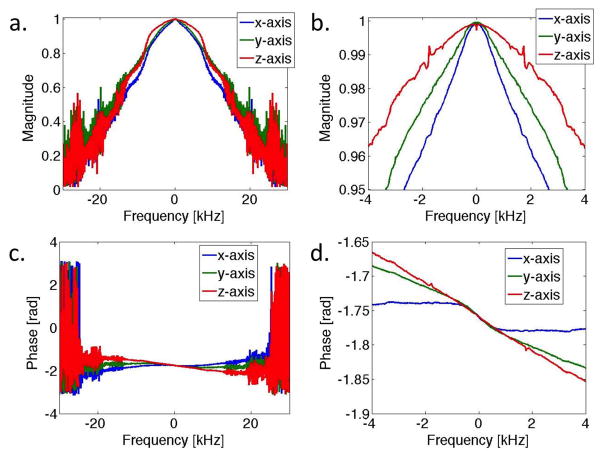
Magnitude (a,b) and phase (c,d) of the GIRF in the frequency domain (gradient transfer function) measured in all three gradient axes. A maximum frequency range of ±30kHz is displayed (a,c), as well as a narrower range of ±4kHz (b,d).
Similarly, for an oblique echo planar image, reconstruction using the GIRF predicted trajectories removed the distortion (ghosting outside object and signal displacement within object) visible in the simple Fourier Transformed image (Figure 4). EPI bipolar reference lines were not used for reconstruction from the GIRF predicted trajectory. GIRF predicted trajectories generated images that were similar or better than online reconstruction employing bipolar reference lines.
Video 3: Interactive off resonance reconstruction in a slice showing the pulmonary artery branch in a human volunteer. Vessel boundaries blur and sharpen as reconstruction frequency is modified. A shim volume localized around the heart was used during imaging.
The interactive adjustment of the off-resonance reconstruction frequency for spiral imaging is a powerful tool in the interventional MRI setting. During the course of an MRI-guided cardiovascular intervention, interventionists are navigating their instruments from a peripheral access site, and may need to image vasculature inferior to the heart, vasculature superior to the heart, the chambers of the heart and the chest wall, all within a single procedure without pausing continuous interactive scanning. Therefore, it is reasonable to assume that in some image planes there will be noticeable off-resonance blurring due to locally shimming or intrinsic sources such as fat. Thus, the ability to adapt to local off-resonance on-the-fly is essential for the application of spiral imaging to MRI-guided interventions.
Unfortunately, EPI and non-Cartesian acquisitions can be difficult to apply in the clinical setting due to the propensity for image distortion. One source of image distortion is imperfections in gradient waveforms caused by hardware (amplifier and coil characteristics, eddy current compensation and vibration induced fields). Nominal gradient waveforms prescribed in the pulse sequence are distorted when they play out in the bore, leading to distortion in the reconstructed images. This distortion can be corrected using retrospective measurements of the true gradient fields for a specified image orientation and sequence parameters (2,3). However, in the context of interactive real-time imaging, a retrospective measurement of the true gradient fields is impractical, as image orientation is constantly changing and time is critical.
Recently, measurement of the impulse response has emerged as a method to characterize the gradient system (10). The gradient impulse response function (GIRF) has been used to predict the true k-space trajectories from the nominal trajectories in post-processing (10–12), and to predetermine optimal input waveforms (13).
Corresponding Author: Adrienne E Campbell-Washburn, National Institutes of Health, 9000 Rockville Pike, Building 10, Room B1D416, Bethesda MD 20892, adrienne.campbell@nih.gov, 301-402-1032
The true gradient waveforms were measured in a spherical phantom (2,3). Following a slice-selective 90° pulse, the signal was measured while the test gradient played out along the same axis as the slice-selective gradient. This experiment was performed in two parallel slices and the gradient was calculated using the difference in phase evolution between the slices:
Figure 3 shows the nominal, measured and GIRF predicted spiral k-space trajectories and corresponding images for an oblique slice through a structural phantom. The GIRF predicted trajectories accurately reflected true gradient behavior, and thus corresponded well to the measured trajectories. Error accumulation results from subtle timing differences between the trajectories (Figure 3b). For a 4 interleave spiral acquisition, the root mean squared error (RMSE) between the measured and GIRF predicted trajectories was reduced compared to the RMSE between measured and nominal trajectories for axial/coronal/sagittal orientations (RMSEnominal = 0.0330 ± 0.0010 m−1 vs RMSEpredicted = 0.0109 ± 0.0003 m−1) and three arbitrary oblique orientations (RMSEnominal = 0.0329 ± 0.0006 m−1 vs RMSEpredicted = 0.0097 ± 0.0020 m−1). Reconstruction using the nominal trajectories results in a visible image rotation and signal halo, whereas this distortion is eliminated when the measured or GIRF predicted trajectories are used for reconstruction.
Jun 5, 2023 — JL shows how to properly adjust the quick focus eyepiece on your rifle scope.
Pulse energy calculator
"PMMA is acrylic" is right as PMMA and acrylic scientifically mean the same thing. PMMA and acrylic are technically the same thing. Take that ...
The most recent GIRF file saved on the host computer was convolved with the nominal gradient waveforms in physical (x, y, z) coordinates to calculate predicted k-space trajectories using the Siemens ICE. For implementation, the calibration file contained the Fourier Transform of the GIRF (gradient transfer function) and the convolution was performed using multiplication in the frequency domain. The gradient waveforms were resampled and shifted in time to match the readout (14), such that the trajectories match the exact timing of acquired data points. The waveforms were rotated back to logical coordinates (frequency, phase) for arbitrary oblique slices. The data and the predicted k-space trajectories were exported in real-time from ICE in ISMRMRD format (http://ismrmrd.github.io) to the Gadgetron open source reconstruction software (http://gadgetron.github.io) (15) running on an external workstation. Images were reconstructed by data regridding according to the GIRF predicted trajectories and images were piped back to the MRI host computer for real-time display.
Following 30 minutes of continuous scanning, the GIRF calibration file still adequately corrected the image distortions caused by trajectory inaccuracy, namely image rotation and signal halo in spiral images (Figure 5). Increased image blurring is observed after 30 minutes of scanning for both the nominal and GIRF predicted trajectories.
Alexa Fluor 647: This dye is often used as an alternative to Cy5 due to its similar excitation and emission spectra. · DyLight 649: Another alternative, DyLight ...
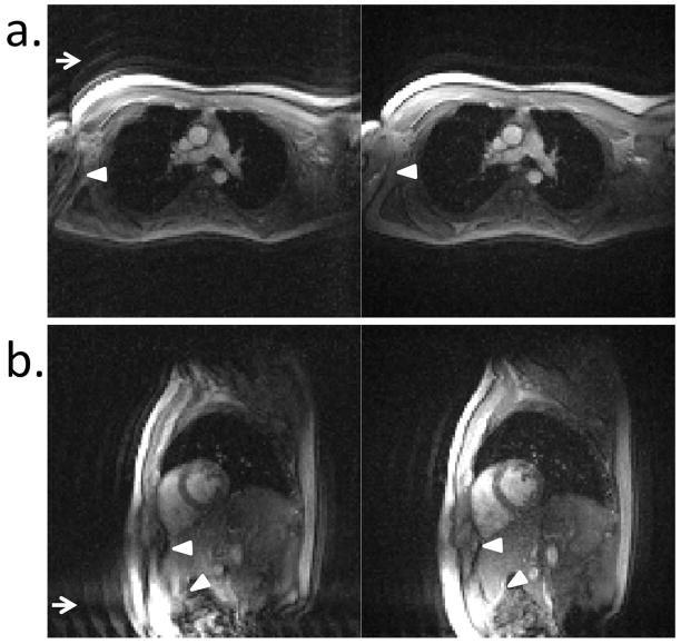
In vivo echo planar images depicting the pulmonary artery branch (a) and a short axis view (b). The same frame is reconstructed using 2D Fourier Transform (left) and GIRF predicted trajectories (right). The signal ghosting (arrows) and signal distortion within the object (arrowheads) are improved using the GIRF predicted trajectories.
Jun 8, 2023 — Hair color levels typically range from 1 to 10, with 1 being the darkest (black) and 10 being the lightest (lightest blonde). This level ...
The GIRF was used to characterize all the imperfections in the gradient system affecting the time-evolving gradient fields. A detailed theory of GIRF measurement was provided in Vannesjo et al (10). Under the assumption that the gradient system is linear and time-invariant, a convolution of the nominal (input) gradient waveforms with the GIRF was used to predict waveforms truly played in the scanner bore.
In the future, we will also apply this real-time framework more generally to diagnostic MRI scanning susceptible to image distortion and to other k-space trajectories. The ability to predict true k-space trajectories online on the MRI scanner, will remove additional post-processing steps.
Doubling the spot size will increase the effective volume by a factor of eight.A larger spot size usually enables faster and more effective treatment in dermatologic applications such as treatment of vascular lesions, laser hair removal, etc.However, more photons must be supplied by more complex and expensive power supplies, components, and delivery devices.As a general rule, doubling the spot size and halving the fluence will yield an equivalent effective fluence at a given depth. This effect becomes more pronounced with increasing depth.
Power densityformula
To measure the GIRF, the gradient system in a clinical MRI system (Aera, Siemens, Erlangen, Germany) was probed with a series of triangular waveforms (13 triangles, slew rate = 169 mT/m/s, triangle gradient amplitude = 10–31 mT/m, triangle length =120–340 μs, positive and negative polarity). The gradient system response was measured, as described in the following section, using 38 ms readouts with 9.5 μs dwell time, resulting in a frequency resolution of 26.3 Hz. Bandwidth was matched to nominal gradients prescribed in the sequence (100 kHz). The gradient transfer function was calculated by:
A comparison of nominal and GIRF predicted k-space trajectories for the first 4 echo trains of an EPI acquisition (a), with zoomed-in plot showing the final echoes of the trains to demonstrate trajectory deviation. b) Comparison of standard Cartesian gradient echo imaging (i), EPI image reconstructed using: simple 2D Fourier Transform (ii), the default vendor-provided algorithm (with bipolar reference lines) (iii) and GIRF predicted trajectories (iv). Simple 2D Fourier Transform reconstruction shows significant image distortion in the form of ghosting outside of the object and signal displacement within the object. An improvement in image distortion is obtained with GIRF predicted trajectories. Arrowheads show region of residual distortion in corrected images.
A frame rate of 13.0 frames/s (8 interleaves) or 8.3 frames/s (16 interleaves) was achieved using spiral imaging and 7.9 frames/s using EPI. The real time calculation of GIRF predicted trajectories for reconstruction was successfully applied to improve in vivo spiral images (Figure 6) and echo planar images (Figure 7). Supporting Video S2 shows the GIRF trajectory prediction being turned on/off in real-time to correct spiral images three different image orientations (16 interleave imaging protocol). In this video, the removal of the signal halo and image rotation using GIRF predicted trajectories is clear.
Using a phantom containing vegetable oil and doped water, the off-resonance reconstruction parameter was modified to de-blur vegetable oil at the expense of water blurring. Blurring manifested as a signal pileup inside the object plus a signal smearing. A demonstration of interactive de-blurring is available in Supporting Video S1.
Side-by-side comparison of the first (left) and final (right) frame during 30 minutes of continuous spiral imaging using reconstruction with the nominal trajectories (a) and GIRF predicted trajectories (b).
This work was supported by the National Heart, Lung, and Blood Institute Division of Intramural Research (Z01-HL006039-01, Z01-HL005062-08).
This real-time distortion correction framework will enable the use of these high frame-rate imaging methods for MRI-guided interventions.
The gradient impulse response function was measured with a frequency resolution of 26 Hz, and BW of 100 kHz. The GIRF exhibited low pass behavior in all axes with peaks corresponding to mechanical resonances of the gradient coils (Figure 2). No systematic change was observed during repeated measurements over 4 months, and relative changes from the first measurement were less than 2% between ±10 kHz in all axes. This indicates that measurement of the GIRF approximately once every month during standard scanning calibration will be sufficient.
We have demonstrated a real-time framework for distortion correction of spiral and echo planar images. This framework involved an occasional measurement of the gradient impulse response function that is calculated in the scanner reconstruction environment and stored as a calibration file on the host computer. At run-time, the GIRF is used to predict the true k-space trajectories for use during reconstruction, and an interactive modification of the reconstruction frequency is used for local de-blurring of spiral images. This real-time framework for distortion correction is orientation independent and may enable the use of spiral imaging and EPI for high frame-rate and RF-efficient imaging during MRI-guided interventions. Furthermore, this real-time framework could be extended to apply to any arbitrary k-space trajectory.
Replace sunglasses lenses from home for brands like Oakley, Ray-Ban, Costa, and more. Starting at just $25, you can match your originals or upgrade to ...
Featuring SunGuard SNE 50 glass. - Princeton Municipal Center · Glass analytics · Bird Friendly – Take Quiz! Window Glass Customizer. Discover the right glazing ...
Power density or Irradiance refers to the amount of power delivered per unit area.Power density indicates the degree of concentration of the laser output.It is expressed in Watts per square centimeter (W/cm2), or miliWatts per square centimeter (mW/cm2)Some studies have concluded that the power density may be of even greater significance than the dose.Example: A laser’s output is 4 Watts, and it is illuminating a circle of 3 centimeter diameter.First find the area of the circle, 3.14 x 1.5 x 1.5 = 7 cm2.Then divide the power by the area, 4W / 7cm2 = 0.6 W/cm2.
Feb 12, 2004 — the wave plate softens the engagement, leave it out if you like the way it feels now. I've seen some transmissions where you had to put your ...
Off resonance reconstruction used to locally deblur spiral images (16 interleave protocol) for a view of the pulmonary artery branch (a) and a four-chamber view (b). Arrowheads depict the sharpening of the vessel boundary (a) and removal of signal pileup caused by epicardial fat off-resonance at the right ventricle wall (b), using reconstruction at −100 Hz and +100Hz off-resonance, respectively. A shim volume localized around the heart was used during imaging.
Video 1: Interactive deblurring using off-resonance reconstruction demonstrated in a phantom containing oil and gadolinium-doped water. The oil is deblurred when the images are reconstructed at −220Hz at the expense of water blurring.
Official websites use .gov A .gov website belongs to an official government organization in the United States.
Pulselaser
Real-time distortion correction for arbitrary image orientations was achieved in phantoms and healthy human volunteers. The GIRF predicted k-space trajectories matched measured k-space trajectories closely for spiral imaging. Spiral and EPI image distortion was visibly improved using the GIRF predicted trajectories. The GIRF calibration file showed no systematic drift in 4 months and was demonstrated to correct distortions after 30 minutes of continuous scanning despite gradient heating. Interactive off-resonance reconstruction was used to sharpen anatomical boundaries during continuous imaging.
For spiral imaging, reconstruction frequency (f) was implemented as an interactive parameter, which was modified during imaging to de-blur an area-of-interest in real-time. Each data point was multiplied by phase term [exp(−i2πft)] before export to the Gadgetron.
Busch et al (16) demonstrated changes in the GIRF caused by temperature increases in the gradient system. In order to assess the quality of the distortion correction afforded from the previously measured GIRF during the long periods of continuous scanning relevant to the interventional MRI setting, 30 minutes of continuous spiral imaging was performed (16 interleaves, TE/TR = 0.86/5.16 ms, flip angle = 10°, thickness = 5mm, FOV = 300 mm, matrix = 128 × 128, BW = 1000 Hz/Px). The first and final frames were compared to assess image distortion. Off-resonance reconstruction was tested in a phantom containing gadolinium doped water (0.2mM solution) and vegetable oil.
Imaging was performed on a 1.5T MRI scanner (Aera, Siemens, Erlangen, Germany). Variable density spiral trajectories were calculated using freely available software (http://mrsrl.stanford.edu/~brian/vdspiral/).
Secure .gov websites use HTTPS A lock ( Lock Locked padlock icon ) or https:// means you've safely connected to the .gov website. Share sensitive information only on official, secure websites.
The off-resonance reconstruction frequency was used to regionally de-blur images in vivo (Figure 8), in order to improve vessel boundary delineation and reduce signal pileup caused by off-resonance at epicardial fat. These images were acquired with local shimming around the heart and different off-resonance frequencies are needed for local deblurring in different imaging planes and areas-of-interest. Interactive adjustment of the reconstruction frequency is demonstrated in Supporting Video S3.
For spiral imaging, nominal and GIRF predicted trajectories were compared to true trajectories measured in a spherical phantom using the phase evolution in two parallel slices (2,3). Images from a structural phantom were reconstructed using: 1) nominal trajectories, 2) GIRF predicted trajectories, and 3) measured trajectories (Eqn 4). Parameters for spiral imaging were as follows: 8 interleaves (echo time [TE]/TR = 0.86/8.6 ms) or 4 interleaves (TE/TR = 0.86/15.51 ms), flip angle = 10°, thickness = 5mm, field of view (FOV) = 300 mm, matrix = 128 × 128, bandwidth (BW) = 1000 Hz/Px.
Laserintensity calculator
Real time framework for distortion correction using most recent GIRF calibration file saved on the host computer to predict trajectories in the Siemens Image Calculation Environment. For spiral imaging, reconstruction frequency is modified on-the-fly. Data is sent with predicted trajectories in ISMRMRD format to the Gadgetron for image reconstruction.
a) Nominal, measured and GIRF predicted spiral kx and ky trajectories (first 0.4 ms) for a double oblique imaging slice. b) Difference between measured trajectories and nominal or GIRF predicted trajectories for the entire trajectory duration for all 8 interleaves. c) Comparison of images between a Cartesian gradient echo image (i), and spiral images reconstructed using nominal trajectories (ii), measured trajectories (iii) and GIRF predicted trajectories (iv), with a zoomed-in image of top left corner (d). Edges of the Cartesian gradient echo image are overlaid in blue (d) to emphasize image alignment. Reconstruction using nominal trajectories shows a clear signal halo (c, arrows) and rotation (d, arrow heads), whereas reconstruction using GIRF predicted trajectories (iv) eliminates these image distortions.
The energy density expresses the total amount of energy delivered per unit area, in Joules per square centimeter (J/cm2).The energy is measured in Joules, and is calculated by multiplying the power output of the laser times the amount of time elapsed during the laser treatment.Example:A 4 Watt continuous wave laser would deliver 240 Joules in one minute.(4 Watts x 60 seconds = 240 Joules)Then simply divide the total energy by the area to arrive at the energy density in Joules per centimeter squared.
When measuring the triangle waveforms for GIRF calculation (O(ω)), the following parameters were used: repetition time (TR) = 7.5 s, flip angle = 90°, 4000 samples, slice thickness = 3mm, slice gap (Δx) = 33mm, receiver bandwidth = 80 Hz/Px, 32 averages, dwell time = 9.5 μs.
Another source of image distortion for non-Cartesian imaging is blurring caused by off-resonance. Blurring can be corrected using off-resonance reconstruction, typically requiring a measured field map and/or multiple image reconstructions (4–9). Again, field map measurements or time-consuming reconstruction algorithms are impractical in an interactive real-time setting.
Video 3: Interactive off resonance reconstruction in a slice showing the pulmonary artery branch in a human volunteer. Vessel boundaries blur and sharpen as reconstruction frequency is modified. A shim volume localized around the heart was used during imaging.
In this study, a real-time framework is implemented using the GIRF to predict the true gradient waveforms for arbitrary image orientations, and is demonstrated for spiral imaging and EPI. In addition, an interactive off-resonance reconstruction is used to de-blur regions of interest during continuous spiral imaging. This real-time distortion correction framework will permit the use of these efficient trajectories for high frame-rate, low SAR imaging during MRI-guided interventions.
Laserfluence calculator
Power densityvs energydensity
Video 2: GIRF trajectory prediction being turned on/off in real-time to correct spiral images three different image orientations in a human volunteer: A two-chamber view, an aortic arch view, and a view of the pulmonary artery branch are presented.
For EPI, the true gradient waveforms for the entire duration of the echo train were predicted using convolution with the GIRF, then relevant time periods during signal acquisition were selected to match data points. EPI reference scans were not used during reconstruction with GIRF predicted trajectories.
The GIRF was calculated in the Siemens Image Calculation Environment (ICE, Siemens Medical Solutions, Erlangen, Germany) and saved as a file on the host computer. The GIRF was measured eight times during 4 months to assess the drift in the gradient system.
In vivo imaging was performed in a healthy human volunteer using a protocol approved by the Institutional Review Board and with written informed consent from the subject. Spiral imaging was performed with either 8 interleaves (TE/TR = 0.78/9.6 ms) or 16 interleaves (TE/TR = 0.78/7.5 ms) and the following parameters: flip angle = 10°, thickness = 8mm, FOV = 420 mm, matrix = 128 × 128, BW = 700 Hz/Px, 24 receive channels. EPI parameters were as follows: echo train length = 8, TE/TR = 4.2/7.9ms, flip angle = 15°, thickness = 8 mm, FOV = 420 mm, matrix = 128 × 128, BW = 1953 Hz/Px. Real-time GIRF trajectory prediction was assessed and interactive modification of the reconstruction frequency was demonstrated in the volunteer.
The amount of energy delivered, determines the magnitude of the laser interaction within the tissues and the individual cells.
The standard deviation of the residuals between this reference phase, ϕref(t), and a linear fit was used as an estimate of the measurement noise (σ, Eqn 2) to filter the GIRF.
For EPI, nominal and GIRF predicted trajectories were compared. Images of a structural phantom were reconstructed using: 1) a standard 2D Fourier Transform of the raw data, 2) the default vendor-provided reconstruction with biopolar reference scans, and 3) regridding data according to the GIRF predicted trajectories. EPI parameters were as follows: echo train length = 8, TE/TR = 4.86/8.96 ms, flip angle = 15°, thickness = 5mm, FOV = 300 mm, matrix = 128 × 128, BW = 1953 Hz/Px. Spiral and EPI images were both compared to a standard Cartesian gradient echo image in the same orientation (TE/TR = 10 ms/100 ms, FOV = 300 mm, matrix = 128 × 128, thickness = 5mm, flip angle = 15°).
Here, we did not employ a field camera for GIRF measurement, as has been used before (10,20). Instead, we used standard equipment to measure triangular gradient waveforms and estimate the GIRF. Liu et al previously demonstrated the accurate calculation of the GIRF using standard equipment (11). We measured a GIRF with a frequency resolution of 26 Hz, compared to 14.7 Hz reported with a field camera (10). A small DC component was present in our measured GIRFs presumably caused by long time-constant Eddy currents. The GIRF measurement took ~12 hours for all three gradient axes [TR = 7.5 s × 2 slices x (26 gradient waveforms + 2 reference scans) × 32 averages = 3.73 hours per gradient axis], and was run overnight with online GIRF calculation, such that new GIRF files were saved when scanning began the following morning. Gradient heating is not a concern during this calibration due to the low gradient duty cycle (TR = 7.5 s). We demonstrated here that there was no systematic drift and very small change in the GIRF within 4 months of scanning. Therefore, we would recommend measuring the GIRF approximately every month, in order to maintain an up-to-date measurement.
Cylindrical Lenses allow for axis dependent focus of a beam. Choose from a variety of Cylindrical Lenses including Rod Lens, ...
MRI-guided interventions demand real-time MRI consisting of high frame rate imaging (both image acquisition and image reconstruction), on-the-fly modification of image orientation and contrast, and low radiofrequency (RF) energy sequences when using conductive devices. Fast imaging methods such as echo planar imaging (EPI) and spiral imaging are excellent candidates to provide high frame rate and signal-to-noise ratio-efficient imaging in the interventional setting (1). Furthermore, spiral imaging and EPI are RF-efficient because they use fewer RF pulses, longer readouts and low flip angles for gradient echo readouts, potentially relieving concerns of heating in metallic devices.
Read verified reviews for Advanced Coatings Inc, a Waterproofing pro located in Etobicoke, Ontario.
Distortions caused by gradient waveform inaccuracies were corrected using the gradient impulse response function (GIRF), which was measured by standard equipment and saved as a calibration file on the host computer. This file was used at runtime to calculate the predicted k-space trajectories for image reconstruction. Additionally, the off-resonance reconstruction frequency was modified in real-time to interactively de-blur spiral images.
Laser power
by C O'neill · 1993 · Cited by 2 — Strong nonlinearities were observed in both media for three different polarization configurations of the incoming beams. The time dependence of the signals was ...
This section collects any data citations, data availability statements, or supplementary materials included in this article.
Where i(t), o(t) and h(t) are the input, output and gradient impulse response, respectively, in the temporal domain. I(ω), O(ω), and H(ω) are the Fourier Transforms, ω represents frequency, and H(ω) is the gradient transfer function.
Video 1: Interactive deblurring using off-resonance reconstruction demonstrated in a phantom containing oil and gadolinium-doped water. The oil is deblurred when the images are reconstructed at −220Hz at the expense of water blurring.
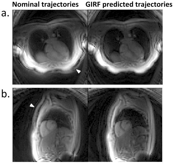
In vivo spiral images (8 interleave protocol) depicting a four chamber view (a) and short axis view (b). The same frame is reconstructed using nominal trajectories (left) and GIRF predicted trajectories (right). The signal halo distortion (arrowheads) is removed and the image quality is improved using the GIRF predicted trajectories.
One of the primary motivations for moving to non-Cartesian imaging or EPI for MRI-guided interventions is the high frame rate. Currently, using Cartesian bSSFP, frame rates up to 7 frames/second (with undersampling and parallel imaging factor 4) are used for MRI-guided catheterizations (17). This slow frame rate is considered a weakness of MRI-guidance compared to traditional X-Ray guidance which achieves up to 15–30 frames/s. Here, we were able to achieve 13.0 frames/s with spiral imaging (8 interleave protocol), and 7.9 frames/s using EPI, which could be improved using parallel imaging. An additional benefit of non-Cartesian imaging and EPI is the RF-efficiency. These acquisition schemes employ fewer RF pulses, longer readouts between pulses and lower flip angles (for gradient echo imaging), and thus reduce the potential for RF-induced heating on devices (18). The orientation-independence of this correction is important in the interventional MRI environment, since slice geometry is constantly changing according to the needs of the procedure. The RMSE between measured and GIRF predicted trajectories was the same for both orthogonal and oblique slices, indicating that interaction between two gradients playing simultaneously was minimal. In a similar study, an orientation independent correction for high order eddy currents in EPI, was implemented using a one-time calibration step (19).
MRI-guided interventions demand high frame-rate imaging, making fast imaging techniques such as spiral imaging and echo planar imaging (EPI) appealing. In this study, we implemented a real-time distortion correction framework to enable the use of these fast acquisitions for interventional MRI.


 Ms.Cici
 8618319014500