
RETRACTA-CADE® Lights Kits - queue lights
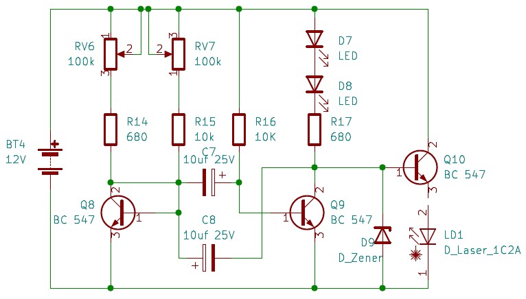
Laser lights are very famous in recent times. Most DIY projects tend to involve at least one laser light into their projects. The above circuit demonstrates a straightforward on how to use a laser as a DIY strobe light. In few modifications can be clearly noticed. A Zener diode can use depending on the laser maximum voltage specification. The value of the Zener diode can be found using the laser diode's datasheet. The reason behind using the Zener diode is the laser diode's protection. The zener diode ensures correct current is passing through it so it won't receive too much light to cause any harm. The zener operates by providing a constant current and a constant voltage.
Konfokale Mikroskope sollen optisch Scheibchen aus dem Präparat separieren und als Bild aufzeichnen. Im günstigsten Fall sind diese Scheibchen etwa gerade so dick wie die Schärfentiefe im Mikroskop. Um dies zu erreichen, wird das Präparat mit einem kleinen Lichtfleck abgerastert – vergleichbar mit dem Rasterprinzip einer altmodischen Fernsehröhre. Der kleinste Fleck, den man durch gewöhnliche optische Linsen erzeugen kann, hat einen „beugungsbegrenzten“ Durchmesser, der Durchmesser wird nur von der Farbe des Lichtes und vom Öffnungswinkel der Linse bestimmt. Es ist das Bild eines unendlich kleinen Lichtpunktes. Die Intensitätsverteilung in der Bildebene nennt man „Punktverwaschungsfunktion“ (engl: point spread function, psf). Tatsächlich ist die Punktverwaschungsfunktion ein dreidimensionales Gebilde; es definiert die Auflösung in allen drei Raumrichtun-gen. Wie diese Intensitätsverteilung (Airy-Muster) in der Fokusebene aussieht ist in Abbildung 1 zu sehen. In der Mitte findet sich ein heller Fleck (das Airy-Scheibchen) und drum herum konzentrische Ringe. Da gewöhnliche Lichtquellen keine unendlich kleinen Punkte sind, sondern endliche Ausdehnung haben, wird das Licht der Lichtquelle auf eine sehr kleine Blende fokussiert, eben auf ein Pinhole, das hier als näherungsweise punktartige Quelle fungiert. Über dieses Pinhole auf der Beleuchtungsseite wird in der Regel nicht gesprochen: Laserlicht lässt sich direkt beugungsbegrenzt fokussieren – ohne Pinhole.
Im Gegensatz zu Pinholedurchmessern über 1 AU, wird bei kleineren Durchmessern auch die laterale Auflösung günstig beeinflusst. Bei Pinhole = 0 kann man eine Verbesserung [4] von etwa 30% erwarten. Diese Verbesserung lässt sich zumindest teilweise ausschöpfen, indem das Pinhole etwas unter 1 AU einge-stellt wird. Beispielsweise können wir schon fast 60% des möglichen Auflösungsgewinnes ernten, wenn wir das Pinhole auf 0,6 AU reduzieren. Um ein gutes Signal-Rausch-Verhältnis auch bei kleineren Durchmessern zu gewährleisten, verwenden wir am besten ein Gerät mit sehr hoher Effizienz für die emittierte Fluoreszenz und fast rauschfreie Sensoren.
XKGLOWStrobe controller
Strobe lights are useful as a self-defence tool in addition to lighting. They currently play a significant role in flashlights. Typical light sources for strobe kits include LEDs, halogen lights, and xenon flash lamps. Additionally, they are the standard blinking mechanism in clubs and party venues. Strobes have a quick recycling time and an output range for a complete flash of 100 to 1,000 watts. Above all, special lighting equipment emits a quick flash of LED strobe light that produces stroboscopic effects. They are also used for industrial, commercial, and medicinal purposes.
Die dünnsten optischen Schnitte erhält man an der Beugungsgrenze in axialer Richtung, wenn das Pinhole den Durchmesser 0 annimmt. Das ist freilich nicht praktisch, weil dann gar kein Signal mehr das Pinhole passieren kann. Tatsächlich ist die Schichtdicke bei Pinhole 0 etwa 25% besser [4] als bei 1 AU.
Eine Alternative zur Verkleinerung des Pinholes um die laterale Auflösung zu verbessern, ist eine „Bild-Rescanning“ genannte Methode [5]. Hier wird sinngemäß das Beu-gungsmuster selbst nochmals abgerastert und die Signale werden auf die zugehörigen Bildelemente verteilt (Abbildung 3, rechts). Durch Berechnung eines neuen synthetischen Bildes lässt sich die laterale Auflösung, verglichen zur Weitfeld-Mikroskopie, etwa um das 1,4-fache verbessern, was etwa der Auflösung beim geschlossenen Pinhole in der konfokalen Mikroskopie entspricht. Die Leistung bezüglich des optischen Schneidens geht jedoch von der Leistung des optischen Schneiden des gesamten gescannten Bereichs aus und folgt den in Abbildung 3 dargestellten Beziehungen.
LED Strobe ControllerModule
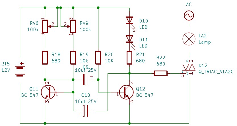
The primary distinction between AC and DC voltages is that the polarity of the wave in an AC voltage varies with time, and it always remains the same in a DC voltage. All the above circuits designed to use DC voltages. The following circuit design shows how to use an AC lamp as a DIY strobe light. This circuit has two main changes. There is a Triac involvement, and the circuit uses AC and DC voltages. The DC voltage operates as the strobe's primary circuit while the AC voltage drives the AC lamp using the Triac.
The terms "strobe flash" and "strobe light" are frequently misunderstood by electronic hobbyists. The strobe flash of light is just as attention-grabbing. As a result, they serve several purposes as entertainment equipment. The flash energy is a key distinction between strobing and flashing, though. However, a strobe light flashes and the manner of the flash is undoubtedly distinct.
A stroboscopic gadget produces strobe effects. Simply put, an LED strobe light emits intense bursts of light. It creates a steady, powerful burst of light. The blue and red overhead lights on a police car are a great illustration of a strobe light.
Strobe Controller12V
Hinzu kommt, dass ein variables Pinhole natürlich die Freiheit des Benutzers sicherstellt, die Schärfe des optischen Schnittes zu verbessern, indem er den Durchmesser kleiner macht. Oder eine dickere Schicht aufzuzeichnen, indem er den Durchmesser erweitertet.
Nicht alle Produkte oder Dienstleistungen sind in allen Märkten zugelassen oder verfügbar, und die Kennzeichnungen und Anweisungen können von Land zu Land unterschiedlich sein. Bitte wenden Sie sich für weitere Informationen an Ihre lokale Leica Vertretung.
Here a torch bulb is using as the light source, as shown in the circuit below. Here it is noticeble that there are minor modifications in the 12v strobe light circuit .
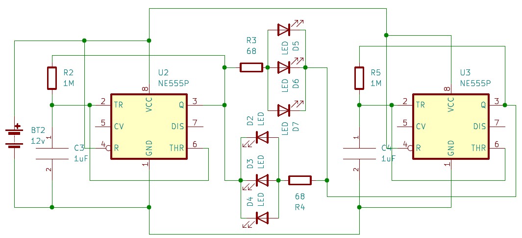
We utilized two identical astable circuits tuned at various frequencies to create this police strobe-style flashing LED circuit. Because the first 555 timer IC has a big capacitor, switching the output takes longer. The output is toggled extremely quickly by the second 555 timer IC since it has a smaller capacitor. When there is a positive voltage at the anode and a negative voltage at the Cathode, the first group of LEDs (the red LEDs) goes ON. This scenario occurs when the outputs of the first and second 555 timer ICs are both ON simultaneously. When the outputs of the first and second 555 timer ICs are turned off simultaneously, the above scenario occurs. Therefore, only the first group of LEDs have a chance of going ON when the output of the first 555 timers IC is ON. They blink at the rate at which the second 555 timer IC toggles the output. Similar to how only the second group of LEDs have a chance of going ON when the first 555 timer IC toggles the output, and they flash at the same rate as the second 555 time IC. This cycle can be repeated endlessly to provide a significant LED flasher effect that resembles the flashing lights on police cars. The construction of the DIY strobe controller is shown in circuit 7.
As in Circuit 1, the circuit uses 12v DC voltage. Therefore this circuit is a 12v strobe light circuit. However, in order to use 5v power input, it is advisable to not use the 330-ohm Resistor due to the voltage drop.
Modifying the above 12v strobe light circuit a little further allows laser light to use instead of LEDs or Motorcycle bulbs, as shown in Citcuit 4.
SafetyStrobeLights
Additionally, stronger and producing extremely brief bursts of light, strobe flashes are used. A strobe light has a pulse-switching light in the meanwhile. Unlike flashing, the strobe light double flash pattern is tailored to produce sharp blinking light flashes (2 x 20ms per second). While flashes clearly have a brief flash duration, compared to strobes, they also have a longer recycle time and less accurate colour.
The 555 timer IC will function as an astable multivibrator in this design. At the output, it will continuously create square pulses. Anode and Cathode are the two terminals of the 1-watt white LED. The duration of these waves, which turn the LED on and off, is determined by the square wave's duty cycle. By adjusting the potentiometer's knob, we can alter the LED's blinking rate. Use an LED heat sink with the LED if you wish to operate this circuit continuously.
LED StrobeLights for trucks
Wer ein konfokales Mikroskop benutzt und über die Eigenschaften und Parameter eines solchen Gerätes diskutiert, wird notwendigerweise über das Pinhole reden – und wie dessen Größe sich auf das Ergebnis auswirkt. Diese kurze einführende Schrift soll die Bedeutung des Pinholes erläutern und ist für Leser gedacht, die nicht allzu viel Zeit mit der Theorie und den Details der konfokalen Mikroskopie verbringen aber dennoch eine Vorstellung über die Wirkungsweise und die Grenzen solcher Instrumente bekommen möchten.
The 100k preset can change the frequency of the lights by switching to the corresponding resistance. 12v strobe light circuit can be further modified as follows.
This article introduces a few methods to implement a DIY strobe controller. Here, the article forcus on desiging transistor-based and 555 timers IC based circuits. Under the transistor-based method, there are five variations according to the type of light source. However, each strobe light circuit diagram was an extension of the primary transistor-based DIY light strobe. There are two 12v strobe light circuit implementations under the 555 timers IC-based light strobe construction. The first one used a single LED to implement the strobe effect, and the second was to implement the police light effect. Two 555 timer IC combined to use in the police car light circuits. However, there are many other methods of implementing a DIY strobe controllers. Suppose you are a hobbyist and have the craving to dig deeper in the field of electronics and circuit designing. In that case, this article is not the end.
Truckstrobe lightmodule
The 555 is an astable multivibrator in this High Intensity LED Strobe Circuit. On the output side, it will provide square pulses that are constant. The LED will on and off by these pulses. By altering the potentiometer connected to the circuit, we may change the pace at which the LED blinks. This time is dependent on the duty cycle of the square wave. Several applications use 555 IC, some of which are as follows.
Nothing is more fascinating than watching an electrical circuit turn an LED on and off. Creating a light strobe is simple, with a suitable drive circuit. Any DIY store will have what you need. This article focuses on two easy ways of DIY strobe light construction such as transistor based method and timer IC 555 based methods. During this article, you will be able to learn many variations of the strobe light controllers. Moreover, this article presents DIY strobe light controllers based on their power usage, such as, AC voltage powered diy strobe controller, DC voltage powered DIY strobe controllers. However, most of the circuits operate at 12v (12v strobe light circuits)
The transistor is an amplification component. It is available in valuable items like hearing aids, one of the earlier devices people used before transistors. Hearing aids use a small microphone to capture noises from your environment and transform them into different electric currents. Additionally, microphones are sent into a transistor, which enhances a tiny loudspeaker so that you may hear an improved version of the sounds around you.
©2024 NEXTPCB All Rights Reserved. Address: 5F, Building 1, Shenzhen New Generation Industrial Park, Futian District, Shenzhen, China. Phone: 0086-755-83643663
Optische Linsen sind im Wesentlichen durch zwei Parameter gekennzeichnet: die Krümmung der Linsenoberflächen und den Durchmesser. Der Krümmungsradius entscheidet, in welche Richtung die Strahlen gebrochen werden und der Durchmesser bestimmt, wieviel Strahlen zum Ergebnisbild beitragen. Der Durchmesser kann im einfachsten Fall durch den Linsenrand gegeben sein, in vielen Fällen wird der Strahldurchmesser aber durch eine separate Blende eingestellt. Oft setzt man Blenden ein, die aus einer größeren Zahl von Lamellen zusammengesetzt sind und deren Durchlass sich durch mechanische Verstellung dieser Lamellen stufenlos einstellen lässt. So eine Vorrichtung heißt Irisblende, nach der im Durchmesser veränderlichen bunten Regenbogenhaut im Auge, die wiederum nach der griechischen Göttin des Regenbogens Iris benannt ist. Sehr kleine Blenden lassen sich mit dieser Lamellentechnik aber nur sehr schwer oder gar nicht fertigen. Die einfachste Methode, mit der sich sehr kleine Blenden herstellen lassen, ist recht trivial: man nehme ein Stück Karton oder Aluminiumfolie und steche mit einer dünnen Nadel ein kleines Loch hinein. So erhält man ein Pinhole (engl. Nadel-Loch). Mit solch einem Pinhole kann man sich eine Camera obscura basteln – ganz ohne Linsen.[1]
EmergencyStrobe Light Controller
All computer chips operate in the same manner. For instance, a memory chip has hundreds of transistors that may all be individually turned on or off. Every transistor has two possible states, allowing it to independently store the integers 0 and 1. With billions of transistors and as many characters and digits, a chip can hold many zeros and ones.
An electronic component known as a transistor can use in circuits to amplify or switch electrical impulses or power, making a vast range of electronic devices possible. Two PN diodes linked back to back form a transistor. It features emitter, base, and collector terminals as its three terminals. The fundamental principle of a transistor is that it enables you to modify the intensity of a much smaller current flowing through a second channel to regulate the current flow through one channel.
Wie oben angedeutet, sollte ein Pinhole für gewöhnliche konfokale Aufnahmen gerade das Airy-Scheibchen übertragen. Das ist ein guter praktischer Kompromiss, kein Naturgesetz. Wird der Durchmesser vergrößert, dann werden nach und nach mehr Beiträge von außerhalb der Fokusebene den Sensor erreichen und das scharfe Bild nach und nach „vernebeln“ [4]. Die Helligkeit des Bildes nimmt also zu und man könnte den Eindruck gewinnen, dass dadurch das Signal-Rausch-Verhältnis verbessert würde. Tatsächlich kommt die Zunahme der Helligkeit nur durch die Wahrnehmung der eigentlich unerwünschten unscharfen Anteile. Wird das Pinhole unendlich groß (= aus dem Strahlengang entfernt), dann verhält sich das Mikroskop wie ein gewöhnliches nicht-konfokales Weitfeld-Mikroskop (vgl. Abbildung 3). Deshalb ist es grundsätzlich nicht empfehlenswert, das Pinhole größer als 1 AU einzustellen, nur um das Schrotrauschen, d.h. das statistische Rauschen, das jedem Lichtstrahl eigen ist, im Bild etwas zu unterdrücken.
This 12V strobe light circuit use a TB122 PNP transisor. This makes the strobe process easier. However, the 100k presets need to adjust appropriately for better results.
Strobe ControllerFlasher Module
Das Schrotrauschen ist eine Folge der Teilchen-Natur des Lichtes. Je heller das Licht, desto geringer das statistische Schrotrauschen. Die laterale Auflösung wird für größere Pin-holedurchmesser nicht beeinflusst und bleibt stets ungefähr bei einem Wert, der auch in der normalen Weitfeld-Mikroskopie erreicht wird und etwa der Abbe‘schen Auflösungsgrenze d=λ/2NA entspricht (Abbildung 4).
Moreover, transistors serve as switches. A tiny electric current can cause a significantly more significant current to flow through one of a transistor's parts and vice versa.
The above mentioned components are required for the DIY strobe controller using 555 timer IC. Timer IC 555 placed with few variable and fixed resistors, as shown in the 12v strobe light circuit diagram. This 12v strobe light circuit power up with a 12 v DC power supply. If you use an external power source, set the voltage to 12 volts. Feed wire connectors are also necessary to connect the individual Resistor and capacitor to the 555 timer device. The connection of the circuit can explaine as follows. First, connect the positive terminal of the power supply, in this case, the 12v DC power supply, to the timer IC 555 pins 4 and 8. Then connect the negative terminal of the power supply, which can also named as the ground terminal in this circuit, to pin 1 of the IC 555 timer. Then, the capacitor terminals can connect, as shown in the 12v strobe light circuit diagram. Next, the variable Resistor and the fixed Resistor placed between six and seven pins of the timer IC 555. The threshold capacitor, which is 0.1uF, is connecting between the ground and pin 2 of the IC 555 timer. 0.01uF capacitor has to connect via pin 5 of timer IC 555 and the ground supply. Then, between pin 7 of the timer IC and the battery holder, the 10k Resistor must be placed. As the final step, the output pin of the IC 555 timer (pin 3) can use to connect the LEDs, as shown in circuit 6.
All these circuits went through a testing process by our circuit moderators to ensure their operation. Therefore, the users can select any circuit design and start building to their liking.
Der Begriff „konfokal“ bezieht sich auf das Arrangement der Beleuchtungs- und Wahrnehmungsflecken. Beide sind auf den gleichen Punkt fokussiert [2]. Die Brennpunkte sind überlagert. Das Bild wird dann dadurch erzeugt, dass das ganze Sehfeld punktweise aufgenommen wird. Der Rastervorgang wird üblicherweise durch eine Anordnung mit meh-reren schwenkbaren Spiegeln (engl: scanning mirrors) verwirklicht. Solche „Scanner“ kennt man auch von der Supermarktkasse oder aus der Disco.
In Abbildung 1 [3] sieht man, wie das Detektions-Pinhole alle Emission abschneidet, die nicht aus der Fokusebene kommt. Es wird daher auch als „Raumfilter“ bezeichnet, der die scharf abgebildeten Anteile herausfiltert und das extrafokale Signal unterdrückt. Da so ein Gerät optische Schnitte aus dem Präparat herausschneidet, nennt man es auch „Optisches Messer“.
Für gewöhnlich wird für die Aufnahme von konfokalen Bildern empfohlen, die Blende gerade so groß zu machen, dass gerade das Airy-Scheibchen übertragen wird (Abbildung 2, links). Dieser Durchmesser wird als Airy-Einheit (engl.: Airy-Unit, AU) bezeichnet. Der Durchmesser dieses Airy-Scheibchens im Zwischenbild hängt ab von der Farbe des Lichtes (seiner Wellenlänge), vom Öffnungswinkel des Objektives (der numerischen Apertur NA), der Vergrößerung des Objektives und von internen Vergrößerungsfaktoren des Mikroskopes. Die NA und die Objektivvergrößerung sind auf dem Objektivgehäuse eingraviert und ändern sich natürlich, wenn man das Objektiv wechselt. Folglich ist auch der vorgeschriebene Pinhole-durchmesser von 1 AU unterschiedlich, wenn die Objektive verschiedene Vergrößerungen und verschiedene Aperturen haben. Ebenso sollte sich der Durchmesser ändern, wenn man blaue, grüne oder rote Emission aufzeichnet.
Um ein optisches Scheibchen zu erhalten, muss der Sensor in gleicher Weise das Präparat abrastern – synchron zur Beleuchtung. Und auch die Detektionsfunktion soll einem beugungsbegrenzten Fleck entsprechen, die beim Rastervorgang stets mit dem Anregungsfleck überlagert ist. So eine beugungsbegrenzte Wahrnehmungsfunktion erhält man, wenn man das vom Präparat ausgesandte Licht durch eine sehr kleine Blende fädelt: das Detektions-Pinhole. Dieses Pinhole ist normalerweise gemeint, wenn man über das Pinhole und seinen Durchmesser in einem konfokalen Mikroskop spricht.


 Ms.Cici
 8618319014500