
ST-Laser Protective Eyewear - laser light eye protection
If the light goes through the retardation plate at an oblique angle, the wavelength changes for which the "λ/4 condition" holds. The effect of this can be seen in figure 3. The explanation is a little bit involved.
Now, let's take a closer look at the lift equation to understand how we can linearly approximate lift values using tangent planes.
Tangential FlightReddit
$$\begin{align} F_{x}(x_{0}, y_{0}, z_{0}) = \frac{ \delta F}{\delta x} \text{ evaluated at } (x_{0}, y_{0}, z_{0}) \\ \\ F_{y}(x_{0}, y_{0}, z_{0}) = \frac{ \delta F}{\delta y} \text{ evaluated at } (x_{0}, y_{0}, z_{0}) \\ \\ F_{z}(x_{0}, y_{0}, z_{0}) = \frac{ \delta F}{\delta z} \text{ evaluated at } (x_{0}, y_{0}, z_{0}) \end{align}$$
The spectacle lenses are horizontal linear polarizers next to the eye to which a retardation foil is laminated. For the right glass, its fast axis goes from top left to bottom right, for the left glass it goes from bottom left to top right.
When an individual enters their desired inputs and clicks "Calculate", the entered values are stored as JavaScript variables which are used for calculations and defining other variables that lead to the final answer.
Think of the hemisphere from Figure 1 and Figure 2 as a bunch of numbers (z-values) that depend on the values of x and y.
Tangential flightmathematics
The glasses in the left half of figure 3 are tilted about the slow axis, those in the right half about the fast axis of the retardation layers. By the tilting, the path length within the plates is increased which increases the optical retardation. Tilting about the slow axis, this is the only effect, the retardation becomes larger. When the tilting is about the fast axis, the refractive index of the extraordinary ray decreases as the electric field is no longer parallel to the optical axis. This more than outweighs the increased path length, leading to a net reduction of the retardation.
The polarization is changed by the quarter wave plate (of the filter in front of the camera's objective) to circular for λ = 555 nm. For longer waves the optical path difference is less than λ/4, elliptical polarization results, with the long axis of the ellipse horizontal. (If the retardation is zero, the light remains horizontally polarized.) For short waves the shift is larger than λ/4, now the shorter axis if the ellipse is horizontal. Therefore, seeing horizontally polarized light through the 3D-glasses, more than 50% of the long waves are transmitted and less than 50% of the short ones which shifts the grey colour to reddish-yellowish. Rotating the filter by 90° (Figure 9) (or tilting one's head with the 3D-glasses by the same amount) the light reflected by the horizontal glass plate is seen bluish.
For RealD® 3-D movies the viewers have to use special glasses which look like sunglasses. The lenses are filters which either block circularly polarized light or convert it to linearly polarized light which then is seen. The image for the right eye is polarized right circularly and is blocked by the left lens (and vice versa). If lit from behind, the right glass creates right circular polarization, the left one performs correspondingly.
To find the equation of a tangent plane, we need to begin by looking at how the surface in three dimensional space is defined. The equation of the aforementioned surface can be defined in two ways:
Tangential FlightCorporation
$$\begin{align} & F_{x}(x_{0}, y_{0}, z_{0})(x \; - \; x_{0}) + F_{y}(x_{0}, y_{0}, z_{0})(y \; - \; y_{0}) + F_{z}(x_{0}, y_{0}, z_{0})(z \; - \; z_{0}) = 0 \hspace{10ex} \bf{(1)} \end{align}$$
What you see is due to the fact that the handedness of circularly polarized light is flipped when reflected by a metallic surface, and that the light reflected by the glass plate is linearly polarized at the chosen observation angle.
Tangential flightreal
The Tangent Plane Calculator uses a combination of HTML (Hypertext Markup Language), CSS (Cascading Style Sheets), and JS (JavaScript). These languages allow the user to type in their desired inputs into a virtual interface, interact with the calculator, and see the custom step-by-step solution to their problem.
If the optical path difference is increased, the red light is blocked more and more while the intensity of the transmitted blue light goes up, yielding dark blue colour. Contrary to this, decreasing the retardation lets more red and yellow light pass while the blue is blocked more strongly, yielding brown (which is dark orange-yellow).
If we define a surface with a function F(x, y, z) = 0, the general equation for the plane tangent to the surface at the specified point (x0, y0, z0) is:
Tangential flightexamples
Our eyes are not equipped to detect polarization. Moreover, circularly polarized light is rare in natural environments. Therefore, the following photographs, except the first one, seem to be weird.
Where x0 is the given x coordinate, y0 is the given y coordinate, and f (x0, y0) is the given function evaluated at x0 and y0.
The answer and solution steps are then showed to the user in an easy-to-follow format that is visually rendered by LaTeX (a document preparation system).
$$\begin{align}& \text{Solution Steps:} \hspace{57ex}& \\ \\ & F(x,y,z) = x^2+y^2+z^2-38 = 0 \; \text{ and } \;(x_{0}, y_{0}, z_{0}) = (3, 2, 5)\\ \\ & \text{1.) The equation of the plane tangent to the surface } F(x, y, z) = 0 \text{ is given as:} \\ \\ & \hspace{3ex} F_{x}(x_{0}, y_{0}, z_{0})(x - x_{0}) + F_{y}(x_{0}, y_{0}, z_{0})(y - y_{0}) + F_{z}(x_{0}, y_{0}, z_{0})(z - z_{0}) = 0 \\ \\ & \hspace{3ex} \text{Where: } \\ & \hspace{3ex} x_{0} \text{ is the given } x \text{ coordinate point, } y_{0} \text{ is the given } y \text{ coordinate point, and }\\ & \hspace{3ex}z_{0} \text{ is the given } z \text{ coordinate point.}\\ \\ & \hspace{3ex} \text{Additionally:} \\ \\ & \hspace{3ex} F_{x}(x_{0}, y_{0}, z_{0}) = \frac{\delta F}{\delta x} \text{ evaluated at }(x_{0}, y_{0}, z_{0}) \\ \\ & \hspace{3ex} F_{y}(x_{0}, y_{0}, z_{0}) = \frac{\delta F}{\delta y} \text{ evaluated at }(x_{0}, y_{0}, z_{0}) \\ \\ & \hspace{3ex} F_{z}(x_{0}, y_{0}, z_{0}) = \frac{\delta F}{\delta z} \text{ evaluated at }(x_{0}, y_{0}, z_{0})\\ \\ &\text{2.) Since } x_{0} = 3\text{, } y_{0} = 2\text{, and } z_{0} = 5\text{ were given, we can begin finding the} \\ & \hspace{3ex} \text{partial derivatives } F_{x} \text{, } F_{y} \text{, and } F_{z} \text{ of the input function } F(x, y, z) \text{.}\\ \\ &\text{3.) Finding } F_{x} \text{, } F_{y} \text{, and } F_{z} \text{ of input function } F(x, y, z) = x^2+y^2+z^2-38 = 0:\\ \\ & \text{3.1) } F_{x} = \frac{\delta F(x, y, z)}{\delta x} \\ \\ & \hspace{5ex} \Longrightarrow \frac{\delta F(x, y, z)}{\delta x} = 2 x\\ \\ & \text{3.2) } F_{y} = \frac{\delta F(x, y, z)}{\delta y} \\ \\ & \hspace{5ex} \Longrightarrow \frac{\delta F(x, y, z)}{\delta y} = 2 y\\ \\ & \text{3.3) } F_{z} = \frac{\delta F(x, y, z)}{\delta z} \\ \\ & \hspace{5ex} \Longrightarrow \frac{\delta F(x, y, z)}{\delta z} = 2 z\\ \\ &\text{4.) Plug the values for } x_{0} \text{, } y_{0} \text{, and } z_{0} \text{ into each result for } F_{x} \text{, } F_{y} \text{, and } F_{z} \\ & \hspace{3ex} \text{found in steps 3.1 - 3.3:}\\ \\ & \text{4.1) } F_{x}(x_{0}, y_{0}, z_{0}) = \frac{\delta F(x, y, z)}{\delta x} \text{ evaluated at } (x_{0} = 3, y_{0} = 2, z_{0} = 5) \\ \\ & \hspace{5ex} \Longrightarrow \frac{\delta F(x, y, z)}{\delta x} = 2 x\\ \\ & \hspace{5ex} \Longrightarrow \left. \frac{\delta F(x, y, z)}{\delta x} \right|_{(3, \;2, \; 5)} = 2(3) = 6\\ \\ & \hspace{5ex} \Longrightarrow \text{Therefore, } F_{x}(x_{0}, y_{0}, z_{0}) = 6\\ \\ & \text{4.2) } F_{y}(x_{0}, y_{0}, z_{0}) = \frac{\delta F(x, y, z)}{\delta y} \text{ evaluated at } (x_{0} = 3, y_{0} = 2, z_{0} = 5) \\ \\ & \hspace{5ex} \Longrightarrow \frac{\delta F(x, y, z)}{\delta y} = 2 y\\ \\ & \hspace{5ex} \Longrightarrow \left. \frac{\delta F(x, y, z)}{\delta y} \right|_{(3, \;2, \; 5)} = 2(2) = 4\\ \\ & \hspace{5ex} \Longrightarrow \text{Therefore, } F_{y}(x_{0}, y_{0}, z_{0}) = 4\\ \\ & \text{4.3) } F_{z}(x_{0}, y_{0}, z_{0}) = \frac{\delta F(x, y, z)}{\delta z} \text{ evaluated at } (x_{0} = 3, y_{0} = 2, z_{0} = 5) \\ \\ & \hspace{5ex} \Longrightarrow \frac{\delta F(x, y, z)}{\delta z} = 2 z\\ \\ & \hspace{5ex} \Longrightarrow \left. \frac{\delta F(x, y, z)}{\delta z} \right|_{(3, \;2, \; 5)} = 2(5) = 10\\ \\ & \hspace{5ex} \Longrightarrow \text{Therefore, } F_{z}(x_{0}, y_{0}, z_{0}) = 10\\ \\ &\text{5.) Plug the following values into the equation of the tangent plane} \\ & \hspace{3ex} \text{for } F(x, y, z) = 0 \text{ and solve for } z \text{:} \\ \\ & \hspace{3ex} \boxed{x_{0} = 3\hspace{3ex} y_{0} = 2\hspace{3ex} z_{0} = 5} \\ \\ & \hspace{3ex} \boxed{F_{x}(x_{0}, y_{0}, z_{0}) = 6\hspace{3ex} F_{y}(x_{0}, y_{0}, z_{0}) = 4\hspace{3ex} F_{z}(x_{0}, y_{0}, z_{0}) = 10}\\ \\ & \text{5.1) The equation of the plane tangent to the surface } F(x, y, z) = 0 \\ & \hspace{5ex} \text{ is given as:} \\ \\ & \hspace{5ex} F_{x}(x_{0}, y_{0}, z_{0})(x - x_{0}) + F_{y}(x_{0}, y_{0}, z_{0})(y - y_{0}) + F_{z}(x_{0}, y_{0}, z_{0})(z - z_{0}) = 0 \\ \\ & \hspace{5ex} \Longrightarrow (6)(x - (3)) + (4)(y - (2)) + (10)(z - (5)) = 0 \\ \\ & \hspace{5ex} \Longrightarrow- 76 + 10 z + 4 y + 6 x = 0\\ \\ & \text{5.2) Solving for } z \text{, we get:} \\ \\ & \hspace{5ex} \Longrightarrow z = - 0.4 y - 0.6 x + 7.6\\ \\ & \text{Therefore, the equation of the plane tangent to the surface } \\ & F(x,y,z) = x^2+y^2+z^2-38 = 0 \; \text{ at } \;(x_{0}, y_{0}, z_{0}) = (3, 2, 5)\text{ is: } \\ \\ & \boxed{\boxed{z = - 0.4 y - 0.6 x + 7.6}}\\ & \end{align}$$
If we define a surface with a function z = f (x, y), the general equation for the plane tangent to the surface at the specified point (x0, y0, f (x0, y0)) is:
Tangential flightinventor
It is important to note that when we say that the tangent plane is tangent to a surface, the surface does not have to be a physical object. In this case, the three dimensional surface we will be discussing is composed of all the possible lift force values (data points) based on the air's density and the velocity of the airflow over the airfoil.
$$\begin{align} & z = f_{x}(x_{0}, y_{0})(x \; - \; x_{0}) + f_{y}(x_{0}, y_{0})(y \; - \; y_{0}) + f(x_{0}, y_{0}) \hspace{10ex} \bf{(2)} \end{align}$$
$$\begin{align} f_{x}(x_{0}, y_{0}) = \frac{ \delta f}{\delta x} \text{ evaluated at } (x_{0}, y_{0}) \\ \\ f_{y}(x_{0}, y_{0}) = \frac{ \delta f}{\delta y} \text{ evaluated at } (x_{0}, y_{0})\end{align}$$
The output fields and calculator are styled with CSS. This includes the size of the calculator, color of the buttons, and all the other visual properties of these elements.
Linear polarization can be converted to circular by means of a birefringent layer, a so-called quarter wave plate or retardation sheet. If the retardation sheet consists of stretched plastic, the molecules of the polymer are aligned in the stretch direction which is called the optical axis or "slow axis", as the speed of a wave oscillating in this direction ("extraordinary ray") is smaller than that of a wave oscillating perpendicular to it in the direction of the "fast axis" ("ordinary ray"). If the retardation is 90� corresponding to a quarter wavelength, this optical device is called a quarter-wave plate.
Figure 4 shows the glasses lying on glossy aluminium foil. There is nothing peculiar to be seen, the mirror image is somewhat blurred but otherwise looks as expected. This is no longer the case in figure 5 where the object is reflected by a black glass plate. The mirror image has darker lenses than the original. Turning the glasses around (figure 6), this is reversed.
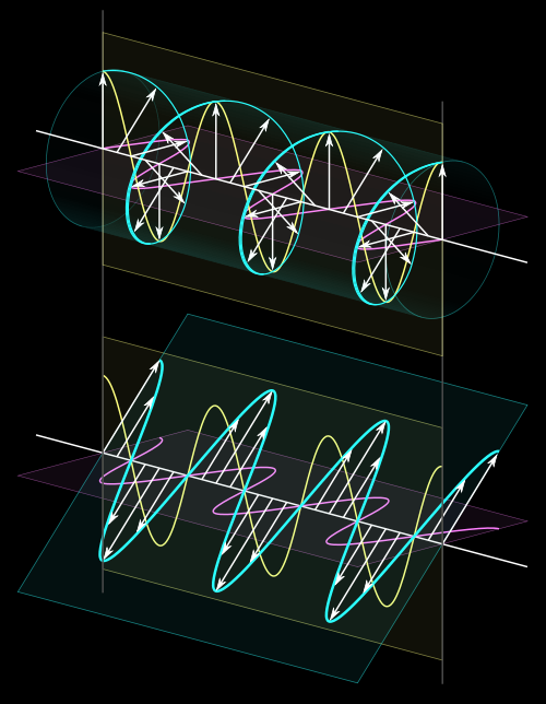
Right: visualization and comparison of circularly and linearly polarized light. The helical wave can be interpreted as a superposition of two waves polarized in orthogonal planes and a relative shift of a quarter of the wavelength. Without this shift the superposition is again linearly polarized as shown in the lower part of the figure. The arrows represent the electrical field strength.
Where x0 is the given x coordinate, y0 is the given y coordinate, and z0 is the given z coordinate. NOTE: If you are only given x0 and y0, you can rearrange your given function into the form: z = f (x, y) and plug in the values x0 and y0 to obtain z0. In other words, z0 = f (x0, y0).
$$\begin{align}& \text{Solution Steps:} \hspace{57ex}& \\ \\ & z = f(x,y) = x^2+2y^2-1\; \text{ and } \; (1, 2)\\ \\ & \text{1.) The equation of the plane tangent to the surface } z = f(x, y) \text{ at the point } \\ & \hspace{3ex} (x_{0}, y_{0}, f(x_{0}, y_{0})) \text{ is given as:} \\ \\ & \hspace{3ex} z = f_{x}(x_{0}, y_{0})(x - x_{0}) + f_{y}(x_{0}, y_{0})(y - y_{0}) + f(x_{0}, y_{0}) \\ \\ & \hspace{3ex} \text{Where: } \\ & \hspace{3ex} x_{0} \text{ is the given } x \text{ coordinate point, } y_{0} \text{ is the given } y \text{ coordinate point, and }\\ & \hspace{3ex} f(x_{0}, y_{0}) \text{ is the input function evaluated at } (x_{0}, y_{0}) \\ \\ & \hspace{3ex} \text{Additionally:} \\ \\ & \hspace{3ex} f_{x}(x_{0}, y_{0}) = \frac{\delta f}{\delta x} \text{ evaluated at }(x_{0}, y_{0}) \\ \\ & \hspace{3ex} f_{y}(x_{0}, y_{0}) = \frac{\delta f}{\delta y} \text{ evaluated at }(x_{0}, y_{0})\\ \\ &\text{2.) Begin by evaluating } f(x_{0}, y_{0}):\\ \\ & \text{2.1) } f(x,y) = x^2+2y^2-1\text{, } x_{0} = 1\text{, and } y_{0} = 2\\ \\ & \hspace{5ex} \Longrightarrow f(1, 2) = -1+2(2)^2+(1)^2\\ \\ & \hspace{5ex} \Longrightarrow f(x_{0}, y_{0}) = f(1, 2) = 8\\ \\ &\text{3.) Now that we have } x_{0} \text{, } y_{0} \text{, and } f(x_{0}, y_{0}) \text{, we can begin finding } f_{x} \text{ and } f_{y} \\ & \hspace{3ex} \text{of input function } \; z = f(x, y) = x^2+2y^2-1:\\ \\ & \text{3.1) } f_{x} = \frac{\delta f(x, y)}{\delta x} \\ \\ & \hspace{5ex} \Longrightarrow \frac{\delta f(x, y)}{\delta x} = 2 x\\ \\ & \text{3.2) } f_{y} = \frac{\delta f(x, y)}{\delta y} \\ \\ & \hspace{5ex} \Longrightarrow \frac{\delta f(x, y)}{\delta y} = 4 y\\ \\ &\text{4.) Plug the values for } x_{0} \text{ and } y_{0} \text{ into each result for } f_{x} \text{ and } f_{y} \\ & \hspace{3ex} \text{found in steps 3.1 and 3.2:}\\ \\ & \text{4.1) } f_{x}(x_{0}, y_{0}) = \frac{\delta f(x, y)}{\delta x} \text{ evaluated at } (x_{0} = 1, y_{0} = 2) \\ \\ & \hspace{5ex} \Longrightarrow \frac{\delta f(x, y)}{\delta x} = 2 x\\ \\ & \hspace{5ex} \Longrightarrow \left. \frac{\delta f(x, y)}{\delta x} \right|_{(1, \;2)} = 2(1) = 2\\ \\ & \hspace{5ex} \Longrightarrow \text{Therefore, } f_{x}(x_{0}, y_{0}) = 2\\ \\ & \text{4.2) } f_{y}(x_{0}, y_{0}) = \frac{\delta f(x, y)}{\delta y} \text{ evaluated at } (x_{0} = 1, y_{0} = 2) \\ \\ & \hspace{5ex} \Longrightarrow \frac{\delta f(x, y)}{\delta y} = 4 y\\ \\ & \hspace{5ex} \Longrightarrow \left. \frac{\delta f(x, y)}{\delta y} \right|_{(1, \;2)} = 4(2) = 8\\ \\ & \hspace{5ex} \Longrightarrow \text{Therefore, } f_{y}(x_{0}, y_{0}) = 8\\ \\ &\text{5.) Plug the following values into the equation of the tangent plane} \\ & \hspace{3ex} \text{for } z = f(x, y) \text{ and solve for } z \text{:} \\ \\ & \hspace{3ex} \boxed{x_{0} = 1\hspace{3ex} y_{0} = 2\hspace{3ex} f(x_{0}, y_{0}) = 8} \\ \\ & \hspace{3ex} \boxed{f_{x}(x_{0}, y_{0}) = 2\hspace{3ex} f_{y}(x_{0}, y_{0}) = 8}\\ \\ & \text{5.1) The equation of the plane tangent to the surface } z = f(x, y) \text{ at } \\ & \hspace{5ex} \text{the point } (x_{0}, y_{0}, f(x_{0}, y_{0})) \text{ is given as:} \\ \\ & \hspace{5ex} z = f_{x}(x_{0}, y_{0})(x - x_{0}) + f_{y}(x_{0}, y_{0})(y - y_{0}) + f(x_{0}, y_{0}) \\ \\ & \hspace{5ex} \Longrightarrow z = (2)(x - (1)) + (8)(y - (2)) + (8)\\ \\ & \text{5.2) After simplifying, we get:} \\ \\ & \hspace{5ex} \Longrightarrow z = - 10 + 2 x + 8 y\\ \\ & \text{Therefore, the equation of the plane tangent to the surface } \\ & z = f(x,y) = x^2+2y^2-1 \; \text{ at } \; (1, 2) \text{ is: } \\ \\ & \boxed{\boxed{z = - 10 + 2 x + 8 y}}\\ & \end{align}$$
The two quarter wave sheets are equivalent to a half wave plate which converts horizontal to vertical linear polarization, but again exactly just for one wavelength (555 nm) which means that some red light and some blue light is able to pass the sandwich, as seen in Figure 1.
Tangential flightvehicles
Note that in the left image, the dark areas are not black, but dark purple. In the middle image, where the first glasses are rotated, the dark area is black. Looking aslant through the opposed glasses, blue and brown colour is seen.
Tangent planes are useful for approximating multivariable functions. This is similar to approximating single variable functions with the use of tangent lines. In the case of tangent planes, we can:
A tangent plane is a plane that is tangent to a smooth surface (characterized by a differentiable function f ) at a specified point.
Tangential flightmeaning
The quarter wave plate is exactly "quarter wave" only for a single wavelength. The best choice for that is at the maximum sensibility of the eye, about 555 nm. As a consequence, the left glass which should block right circular light, lets through a little bit of long-wave (red) and short-wave (blue) light; instead of black in Figure 1, we see dark violet which is a mixture of red and blue. Correspondingly, linearly polarized light after passing the λ/4 plate is exactly circular only for the one wavelength; for other wavelengths a small percentage of the opposite handedness remains. Visualizing the electric field on a fixed point by an arrow, the arrowhead moves along an ellipse (elliptical polarization).
Where L is the lift force, CL is the lift coefficient, ρ is the air density at a particular altitude, V is the velocity of the airflow over the wing, and A is the wing area.
In movie projection, this undesired admixture of colour can completely be avoided. It is only necessary that the polarizing filter at the projector is rotated 90° with respect to the analyzing filters in the eyeglasses. The second figure demonstrates this. The second quarter wave plate undoes the effect of the first one and the extinction is as good as that of two crossed linear polarizers.
If we hold CL and A constant, then we have a function L = f (ρ, V). If we have initial data on what the lift force is for a given air density (ρ) and velocity (V), then we can find the equation of the plane tangent to the surface L = f (ρ, V) at (ρ0, V0). We can then use the tangent plane equation to approximate other lift values that are sufficiently close to our initial parameters (ρ0, V0).
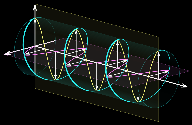
A right circular wave, to the left represented as the sum of two linear waves, to the right visualized by an animation which ist switched on by a double and off by a single click.
For the next three pictures, the right lens of RealD 3D glasses has been used as a filter in front of the camera's objective lens. Figure 7 shows that the handedness of the circular rays is flipped when reflected by a metal surface. The blue colour (instead of violet) again is due to the inclined viewing angle.
If now the incident light is linearly polarized at an angle of 45� to the optical axis of the quarter-wave plate, the outgoing light is circularly polarized. Conversely, circular polarization is converted to linear by a λ/4 plate.
The light reflected by the glass plate is horizontally linearly polarized, as the reflection angle is very close to the Brewster angle.
How does this translate to reality? We can utilize tangent planes to approximate the lift force of an airfoil (cross-section of an airplane's wing in this case) with varying altitudes and speeds based on preliminary test data.
Let us trace one ray: it first passes a linear polarizer, then the λ/4-layer on top of it, after a short distance through air the λ/4-layer and then the linear polarizer of the opposite second spectacle lens.


 Ms.Cici
 8618319014500