
Pupil of the Eye: Definition, Anatomy & Function - admits light
Light measurementdevice

Human vision depends on light. Light reflects off surfaces into the eyes, passing through the cornea and pupil to form an image on the retina. The eye is sensitive to a very wide range of light intensity but at low levels loses the ability to discern detail. That’s why precision work like surgery, measurement or assembly is best done under bright light. Working under poor lighting causes fatigue and mistakes. Industrial accidents are more common when light levels are low. In addition, good lighting determines how well people can observe a show and take quality photographs. To aid in understanding light intensity measurement this White Paper from OMEGA Engineering addresses: What is light? How light is measured? Situations needing light measurement Light measurement technology Light measurement equipment
Circularly polarized luminescence (CPL) can occur when either a luminophore or an ensemble of luminophores is chiral. The extent to which emissions are polarized is quantified in the same way it is for circular dichroism, in terms of the dissymmetry factor, also sometimes referred to as the anisotropy factor. This value is given by:
The classical sinusoidal plane wave solution of the electromagnetic wave equation for the electric and magnetic fields is:
In the quantum mechanical view, light is composed of photons. Polarization is a manifestation of the spin angular momentum of light. More specifically, in quantum mechanics, the direction of spin of a photon is tied to the handedness of the circularly polarized light, and the spin of a beam of photons is similar to the spin of a beam of particles, such as electrons.[17]
Circular polarization may be referred to as right-handed or left-handed, and clockwise or anti-clockwise, depending on the direction in which the electric field vector rotates. Unfortunately, two opposing historical conventions exist.
Radio astronomers also use this convention in accordance with an International Astronomical Union (IAU) resolution made in 1973.[8]
Islightmeasured in wavelengths
Circular dichroism (CD) is the differential absorption of left- and right-handed circularly polarized light. Circular dichroism is the basis of a form of spectroscopy that can be used to determine the optical isomerism and secondary structure of molecules.
This convention is in conformity with the Institute of Electrical and Electronics Engineers (IEEE) standard and, as a result, it is generally used in the engineering community.[4][5][6]

Circularly polarized light can be converted into linearly polarized light by passing it through a quarter-waveplate. Passing linearly polarized light through a quarter-waveplate with its axes at 45° to its polarization axis will convert it to circular polarization. In fact, this is the most common way of producing circular polarization in practice. Note that passing linearly polarized light through a quarter-waveplate at an angle other than 45° will generally produce elliptical polarization.
Light measurementapp
Circular polarization occurs when the two orthogonal electric field component vectors are of equal magnitude and are out of phase by exactly 90°, or one-quarter wavelength.
The handedness of polarized light is reversed reflected off a surface at normal incidence. Upon such reflection, the rotation of the plane of polarization of the reflected light is identical to that of the incident field. However, with propagation now in the opposite direction, the same rotation direction that would be described as "right-handed" for the incident beam, is "left-handed" for propagation in the reverse direction, and vice versa. Aside from the reversal of handedness, the ellipticity of polarization is also preserved (except in cases of reflection by a birefringent surface).
As a specific example, refer to the circularly polarized wave in the first animation. Using this convention, that wave is defined as right-handed because when one points one's right thumb in the same direction of the wave's propagation, the fingers of that hand curl in the same direction of the field's temporal rotation. It is considered clockwise circularly polarized because, from the point of view of the source, looking in the same direction of the wave's propagation, the field rotates in the clockwise direction. The second animation is that of left-handed or anti-clockwise light, using this same convention.
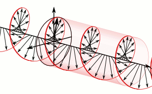
In a circularly polarized electromagnetic wave, the individual electric field vectors, as well as their combined vector, have a constant magnitude, and with changing phase angle. Given that this is a plane wave, each vector represents the magnitude and direction of the electric field for an entire plane that is perpendicular to the optical axis. Specifically, given that this is a circularly polarized plane wave, these vectors indicate that the electric field, from plane to plane, has a constant strength while its direction steadily rotates. Refer to these two images[dead link] in the plane wave article to better appreciate this dynamic. This light is considered to be right-hand, clockwise circularly polarized if viewed by the receiver. Since this is an electromagnetic wave, each electric field vector has a corresponding, but not illustrated, magnetic field vector that is at a right angle to the electric field vector and proportional in magnitude to it. As a result, the magnetic field vectors would trace out a second helix if displayed.
The bioluminescence of the larvae of fireflies is also circularly polarized, as reported in 1980 for the species Photuris lucicrescens and Photuris versicolor. For fireflies, it is more difficult to find a microscopic explanation for the polarization, because the left and right lanterns of the larvae were found to emit polarized light of opposite senses. The authors suggest that the light begins with a linear polarization due to inhomogeneities inside aligned photocytes, and it picks up circular polarization while passing through linearly birefringent tissue.[20]
Using this convention, the electric field vector of a left-handed circularly polarized wave is as follows: ( E x , E y , E z ) ∝ ( cos 2 π λ ( c t − z ) , − sin 2 π λ ( c t − z ) , 0 ) . {\displaystyle \left(E_{x},\,E_{y},\,E_{z}\right)\propto \left(\cos {\frac {2\pi }{\lambda }}\left(ct-z\right),\,-\sin {\frac {2\pi }{\lambda }}\left(ct-z\right),\,0\right).}
"... two crossed dipoles provide the two orthogonal field components.... If the two dipoles are identical, the field intensity of each along zenith ... would be of the same intensity. Also, if the two dipoles were fed with a 90° degree time-phase difference (phase quadrature), the polarization along zenith would be circular.... One way to obtain the 90° time-phase difference between the two orthogonal field components, radiated respectively by the two dipoles, is by feeding one of the two dipoles with a transmission line which is 1/4 wavelength longer or shorter than that of the other," p.80;
To avoid confusion, it is good practice to specify "as defined from the point of view of the source" or "as defined from the point of view of the receiver" when discussing polarization matters.
Only a few mechanisms in nature are known to systematically produce circularly polarized light. In 1911, Albert Abraham Michelson discovered that light reflected from the golden scarab beetle Chrysina resplendens is preferentially left-polarized. Since then, circular polarization has been measured in several other scarab beetles such as Chrysina gloriosa,[18] as well as some crustaceans such as the mantis shrimp. In these cases, the underlying mechanism is the molecular-level helicity of the chitinous cuticle.[19]
The next pair of illustrations is that of left-handed, counterclockwise circularly polarized light when viewed by the receiver. Because it is left-handed, the rightward (relative to the direction of travel) horizontal component is now lagging the vertical component by one quarter of a wavelength, rather than leading it.
The phenomenon of polarization arises as a consequence of the fact that light behaves as a two-dimensional transverse wave.
When determining if the wave is clockwise or anti-clockwise circularly polarized, one again takes the point of view of the receiver and, while looking toward the source, against the direction of propagation, one observes the direction of the field's temporal rotation.
Light is a form of electromagnetic energy that travels through space as a wave. Like microwaves and x-rays those waves have a wavelength and a frequency. The difference is that humans possess receptors able to sense energy with wavelengths between 400 and 700 nm and turn it into images. Individual wavelengths correspond to distinct colors. Light with a wavelength around 420 nm is perceived as blue, 525 nm is green and 635 nm is red. Longer wavelengths are termed infrared (which is sensed as heat) and shorter waves are ultraviolet and then x-rays. Light sources based on heat (“incandescent” sources) radiate electromagnetic energy across all wavelengths, which is why they appear white. The actual distribution of wavelengths within that light depends on the temperature of the source. Fluorescent lights appear white only as a result of fluorescence from a coating on the glass or tube and LEDs emit light only at one specific wavelength.
In electrodynamics, circular polarization of an electromagnetic wave is a polarization state in which, at each point, the electromagnetic field of the wave has a constant magnitude and is rotating at a constant rate in a plane perpendicular to the direction of the wave.
As stated earlier, there is significant confusion with regards to these two conventions. As a general rule, the engineering, quantum physics, and radio astronomy communities use the first convention, in which the wave is observed from the point of view of the source.[5][7][8] In many physics textbooks dealing with optics, the second convention is used, in which the light is observed from the point of view of the receiver.[7][9]
Light measurementunit K
Note that the IEEE defines RHCP and LHCP the opposite as those used by physicists. The IEEE 1979 Antenna Standard will show RHCP on the South Pole of the Poincare Sphere. The IEEE defines RHCP using the right hand with thumb pointing in the direction of transmit, and the fingers showing the direction of rotation of the E field with time. The rationale for the opposite conventions used by Physicists and Engineers is that Astronomical Observations are always done with the incoming wave traveling toward the observer, where as for most engineers, they are assumed to be standing behind the transmitter watching the wave traveling away from them. This article is not using the IEEE 1979 Antenna Standard and is not using the +t convention typically used in IEEE work.
To appreciate how this quadrature phase shift corresponds to an electric field that rotates while maintaining a constant magnitude, imagine a dot traveling clockwise in a circle. Consider how the vertical and horizontal displacements of the dot, relative to the center of the circle, vary sinusoidally in time and are out of phase by one quarter of a cycle. The displacements are said to be out of phase by one quarter of a cycle because the horizontal maximum displacement (toward the left) is reached one quarter of a cycle before the vertical maximum displacement is reached. Now referring again to the illustration, imagine the center of the circle just described, traveling along the axis from the front to the back. The circling dot will trace out a helix with the displacement toward our viewing left, leading the vertical displacement. Just as the horizontal and vertical displacements of the rotating dot are out of phase by one quarter of a cycle in time, the magnitude of the horizontal and vertical components of the electric field are out of phase by one quarter of a wavelength.
If α y {\displaystyle \alpha _{y}} is rotated by π / 2 {\displaystyle \pi /2} radians with respect to α x {\displaystyle \alpha _{x}} and the x amplitude equals the y amplitude, the wave is circularly polarized. The Jones vector is:
where the plus sign indicates left circular polarization, and the minus sign indicates right circular polarization. In the case of circular polarization, the electric field vector of constant magnitude rotates in the x-y plane.
Rugged Handheld Environmental Meters for RPM and Light Measurement are designed as easy-to-use handheld instruments for measuring light intensity. Based on the CIE Standard Illuminant A, these units are ideal for use in areas of incandescent lighting, and will provide a reading under fluorescent lighting with a small error with a measuring range from 1 to 200,000 lux (0 to 18,580 foot candles). These instruments are ideal for anyone needing to verify light levels in indoor work environments, for photography, theater set design, interior design and cinematography. It can be used outdoors where comparative values or ratios are sufficient but should not be relied upon for accurate intensity values owing to its CIE calibration.
FM broadcast radio stations sometimes employ circular polarization to improve signal penetration into buildings and vehicles. It is one example of what the International Telecommunication Union refers to as "mixed polarization", i.e. radio emissions that include both horizontally- and vertically-polarized components.[14] In the United States, Federal Communications Commission regulations state that horizontal polarization is the standard for FM broadcasting, but that "circular or elliptical polarization may be employed if desired".[15]
Light measurementfor plants
To convert circularly polarized light to the other handedness, one can use a half-waveplate. A half-waveplate shifts a given linear component of light one half of a wavelength relative to its orthogonal linear component.
is the angular frequency of the wave; Q = [ x ^ , y ^ ] {\displaystyle \mathbf {Q} =\left[{\hat {\mathbf {x} }},{\hat {\mathbf {y} }}\right]} is an orthogonal 2 × 2 {\displaystyle 2\times 2} matrix whose columns span the transverse x-y plane; and c {\displaystyle c} is the speed of light.
Also, under the right conditions, even non-chiral molecules will exhibit magnetic circular dichroism — that is, circular dichroism induced by a magnetic field.
The nature of circular polarization and its relationship to other polarizations is often understood by thinking of the electric field as being divided into two components that are perpendicular to each other. The vertical component and its corresponding plane are illustrated in blue, while the horizontal component and its corresponding plane are illustrated in green. Notice that the rightward (relative to the direction of travel) horizontal component leads the vertical component by one quarter of a wavelength, a 90° phase difference. It is this quadrature phase relationship that creates the helix and causes the points of maximum magnitude of the vertical component to correspond with the points of zero magnitude of the horizontal component, and vice versa. The result of this alignment are select vectors, corresponding to the helix, which exactly match the maxima of the vertical and horizontal components.
Using this convention, polarization is defined from the point of view of the source. When using this convention, left- or right-handedness is determined by pointing one's left or right thumb away from the source, in the same direction that the wave is propagating, and matching the curling of one's fingers to the direction of the temporal rotation of the field at a given point in space. When determining if the wave is clockwise or anti-clockwise circularly polarized, one again takes the point of view of the source, and while looking away from the source and in the same direction of the wave's propagation, one observes the direction of the field's temporal rotation.
A light source, like the filament of an incandescent bulb, emits light in all directions. Effectively, it sits at the center of a sphere of radiated light (which is why light units reference the steradian). The total energy of all the light given off is termed the “luminous flux.” The fundamental unit of light is the candela, nominally the light given off by one candle, or more precisely, “a source that emits monochromatic radiation of frequency 540 x 1012 hertz and that has a radiant intensity in that direction of 1/683 watt per steradian.” One candela per steradian is termed a lumen, which is the measure of light intensity people are most familiar with. However, what matters most in terms of measuring light intensity is the number of lumens falling on a surface, which is expressed as lux. So one lux is one lumen per square meter, this relating brightness to distance from the source. (In the US it’s common to express light intensity in unit of foot-candles. One foot-candle is equivalent to one lumen per square foot). Summarizing, while light output is expressed in lumens, light intensity is measured in terms of lumens per square meter or lux.
lightunits of measure w/m2
Water-air interfaces provide another source of circular polarization. Sunlight that gets scattered back up towards the surface is linearly polarized. If this light is then totally internally reflected back down, its vertical component undergoes a phase shift. To an underwater observer looking up, the faint light outside Snell's window therefore is (partially) circularly polarized.[22]
In general, this phenomenon will be exhibited in absorption bands of any optically active molecule. As a consequence, circular dichroism is exhibited by most biological molecules, because of the dextrorotary (e.g., some sugars) and levorotary (e.g., some amino acids) molecules they contain. Noteworthy as well is that a secondary structure will also impart a distinct CD to its respective molecules. Therefore, the alpha helix, beta sheet and random coil regions of proteins and the double helix of nucleic acids have CD spectral signatures representative of their structures.
"... circular and elliptical polarizations can be obtained using various feed arrangements or slight modifications made to the elements.... Circular polarization can be obtained if two orthogonal modes are excited with a 90° time-phase difference between them. This can be accomplished by adjusting the physical dimensions of the patch.... For a square patch element, the easiest way to excite ideally circular polarization is to feed the element at two adjacent edges.... The quadrature phase difference is obtained by feeding the element with a 90° power divider," p.859.
"To achieve circular polarization [in axial or end-fire mode] ... the circumference C of the helix must be ... with C/wavelength = 1 near optimum, and the spacing about S = wavelength/4," p.571;
Light measurementunit lux
The main reasons for measuring light intensity are to ensure that minimum standards of illumination are being met, and to determine appropriate exposure times in photography and cinematography. Four commonly encountered situations are set out below. 1. Ergonomics and Safety Minimum illumination levels are recommended for many environments. While some, such as construction and shipyards, have very specific OSHA requirements, for general industrial applications OSHA refers to ANSI/IESNA RP-7-2001 standard, “Practice for Industrial Lighting.” This defines the minimum intensity required to safely and accurately perform a range of tasks. In some organizations light intensity is only measured reactively, typically after a fall or other accident. A more prudent approach is to perform a lighting survey, documenting light levels throughout the workplace. If areas are found below the minimum acceptable levels an improvement plan can then be implemented. 2. Photography and Cinematography Light intensity is at the heart of photography. Low light forces a photographer to increase exposure time or open up the lens aperture, and sometimes both. While many modern cameras have light metering built-in it’s still advantageous to know light levels around the subject, especially for studio or portrait photography. Knowing light levels also helps ensure the reproducibility of a shot, something of concern in cinematography. By measuring light levels a cameraman can produce consistent results, ensuring continuity is maintained. 3. Weather Monitoring While many light meters are configured for incandescent light they are still useful for providing comparisons outdoors. A meter could for example produce records showing the difference in intensity between the summer and winter solstice. Mapping light intensities in an area designated for solar arrays could help determine the optimal location for each panel. Those involved in agriculture may benefit from identifying areas of lower light intensity within a greenhouse. 4. Theater Set and Interior Design Differences in light intensities is an effective way of directing an audience’s attention. A set designer may want a particular prop or actor cast in shadow for one scene and highlighted for the next. Likewise, an interior designer will use differences in intensity to create a particular look and feel. Establishing light levels also helps ensure the reproducibility of a particular look and feel as well as confirming that there is sufficient light for the audience to see the actors’ features.
Lightintensitymeasurementunit
Weaker sources of circular polarization in nature include multiple scattering by linear polarizers[dubious – discuss], as in the circular polarization of starlight, and selective absorption by circularly dichroic media.
where θ l e f t {\displaystyle \theta _{\mathrm {left} }} corresponds to the quantum yield of left-handed circularly polarized light, and θ r i g h t {\displaystyle \theta _{\mathrm {right} }} to that of right-handed light. The maximum absolute value of gem, corresponding to purely left- or right-handed circular polarization, is therefore 2. Meanwhile, the smallest absolute value that gem can achieve, corresponding to linearly polarized or unpolarized light, is zero.
Circular polarization is a limiting case of elliptical polarization. The other special case is the easier-to-understand linear polarization. All three terms were coined by Augustin-Jean Fresnel, in a memoir read to the French Academy of Sciences on 9 December 1822.[1][2] Fresnel had first described the case of circular polarization, without yet naming it, in 1821.[3]
Circular polarization is often encountered in the field of optics and, in this section, the electromagnetic wave will be simply referred to as light.
In electrodynamics, the strength and direction of an electric field is defined by its electric field vector. In the case of a circularly polarized wave, the tip of the electric field vector, at a given point in space, relates to the phase of the light as it travels through time and space. At any instant of time, the electric field vector of the wave indicates a point on a helix oriented along the direction of propagation. A circularly polarized wave can rotate in one of two possible senses: right-handed circular polarization (RHCP) in which the electric field vector rotates in a right-hand sense with respect to the direction of propagation, and left-handed circular polarization (LHCP) in which the vector rotates in a left-hand sense.
Light falls on a sensor where the energy of the photons is converted to electrical charge. The more light that strikes the surface, the more charge is built up. In general terms the two are correlated. A calibration in the measurement electronics converts either current or voltage to a lux value. Complicating matters, the human eye is not equally sensitive to all wavelengths of light and has greater sensitivity to green. Thus if equal intensities of blue light and green light fall on a meter, while the raw lux value might be the same the human observer would perceive more green light. To address this, lux meters are configured to expect light with the spectral distribution of domestic, tungsten-filament lighting. This is defined as CIE standard illuminant A and adjusts the raw intensity measurement to better correlate with the human perception of brightness. CIE standard illuminant A is recommended for use in all applications involving the use of incandescent lighting.
When using this convention, in contrast to the other convention, the defined handedness of the wave matches the handedness of the screw type nature of the field in space. Specifically, if one freezes a right-handed wave in time, when one curls the fingers of one's right hand around the helix, the thumb will point in the direction of progression for the helix, given the sense of rotation. Note that, in the context of the nature of all screws and helices, it does not matter in which direction you point your thumb when determining its handedness.
Note that this principle only holds strictly for light reflected at normal incidence. For instance, right circularly polarized light reflected from a dielectric surface at grazing incidence (an angle beyond the Brewster angle) will still emerge as right-handed, but elliptically polarized. Light reflected by a metal at non-normal incidence will generally have its ellipticity changed as well. Such situations may be solved by decomposing the incident circular (or other) polarization into components of linear polarization parallel and perpendicular to the plane of incidence, commonly denoted p and s respectively. The reflected components in the p and s linear polarizations are found by applying the Fresnel coefficients of reflection, which are generally different for those two linear polarizations. Only in the special case of normal incidence, where there is no distinction between p and s, are the Fresnel coefficients for the two components identical, leading to the above property.
In this alternative convention, polarization is defined from the point of view of the receiver. Using this convention, left- or right-handedness is determined by pointing one's left or right thumb toward the source, against the direction of propagation, and then matching the curling of one's fingers to the temporal rotation of the field.
Many optics textbooks use this second convention.[9][10] It is also used by SPIE[11] as well as the International Union of Pure and Applied Chemistry (IUPAC).[12]
A number of different types of antenna elements can be used to produce circularly polarized (or nearly so) radiation; following Balanis,[16] one can use dipole elements:
Quantum physicists also use this convention of handedness because it is consistent with their convention of handedness for a particle's spin.[7]
Just as in the other convention, right-handedness corresponds to a clockwise rotation, and left-handedness corresponds to an anti-clockwise rotation.


 Ms.Cici
 8618319014500