
Products | AI Wi-Fi Controller - ai led lights
The image of a specimen in phase contrast can be influenced by appropriately selecting the retardation of the direct (non-diffracted) beam through careful selection of the phase ring in the objective. Depending on the retardation value selected, objects with a higher refractive index than their surroundings appear either brighter or darker than their surroundings. This is also called either positive or negative phase contrast. In modern microscopes, positive phase contrast is standard, where the darkness of object features increases with their refractive index. The effect simulates absorption to the observer's eye in areas where a higher refractive index produces high contrast features. This impression is considered the optimum, particularly with cells and tissue in aqueous media because cell nuclei and organelles, for example, appear darker than the cytoplasm. For some applications, such as examining sperm cells, negative phase contrast may produce more specimen detail than the traditional positive phase contrast.

Recently, a renewed interest in transmitted darkfield microscopy has arisen due to its advantages when used in combination with fluorescence microscopy. Darkfield microscopy is a specialized illumination technique that capitalizes on oblique illumination, as described above, to enhance contrast in specimens that are not imaged well under normal brightfield illumination conditions. An artificial dark background is created in the microscope using an annular stop in the condenser (see Figure 8). Although the condenser optics then illuminate the sample, they do so with a hollow inverted cone of light that passes through the specimen at extremely oblique angles at all azimuths so that only the light interacting with specimen features is able to enter the microscope objective to form a bright image of the specimen superimposed onto a dark background. To create the high angles, it is necessary for the objective aperture to be smaller than the inner aperture of the illuminating light cone (see Figure 8(a)). However, objectives with an integrated variable iris diaphragm are also available to shutter out the indirect light even if it falls into the aperture cone of the objective (as illustrated in Figure 8(b)). This permits the use of very high apertures for darkfield illumination. Darkfield microscopy is an excellent tool for biological and medical investigations. It can be effectively used at high magnifications to image living bacteria, or at low magnifications to view and image cells, tissues, and whole mounts.
Hunter earned a Ph.D. in Materials Science and Engineering at the University of Illinois at Urbana-Champaign, before joining Los Alamos National Laboratory in the Chemistry Division. Ultimately the value proposition of UbiGro is about boosting crop yields and quality without the cost or energy impact of lighting. Hunter has more than fifty publications and patents, and more than 2000 total citations, h-index: 20. Hunter fundamentally believes that novel materials underpin every significant technology advancement, and he is focused on leveraging new materials to have a lasting and sustainable impact.
In transmitted light microscopy, the specimen quality does not always lend itself to easy observation and image recording with excellent contrast in simple brightfield imaging mode. Investigations dealing with inherently low-contrast specimens, such as unstained bacteria, thin tissue slices, and adherent live cells, rely on specialized contrast-enhancing techniques to assist with imaging these virtually transparent samples. In the course of examining unstained specimens, poor light absorption by the specimen results in extremely small variations in the intensity distribution difference between the specimen and the background. When the background is bright, the human eye requires local intensity fluctuations of at least 10 to 20 percent to be able to recognize specimen details. Unfortunately, this level of modulation is seldom seen with transparent specimens, which are usually rendered almost invisible against a background of similar intensity. The term transmitted light, when used in optical microscopy, refers to any imaging modality where light is passed from the illumination source on the opposite side of the specimen to the objective (thus, illumination is transmitted through the specimen). The contrast-enhancing techniques described in this section represent a variety of methods in sample preparation as well as optical tricks that generate intensity changes which are useful for observation and imaging.
Tania is a UbiGro Sales Representative, with over 7 years of experience in product sales (specifically berries and avocados) covering all of North America and parts of South America. While in agriculture, Tania has cultivated strong relationships with growers and distributors, granting her a unique insight into both perspectives. That understanding, paired with her fierce dedication to results, drives her fun and fiery commitment to her craft. Tania is based in Gilroy, CA.
Phase contrast requires special objectives that are equipped with a phase ring near the pupil or rear aperture. They are easy to recognize by the green inscription that denotes the size of the corresponding condenser phase stop: Ph1, Ph2, or Ph3. If you hold such an objective against the light and look into the pupil from the threaded end, you will be able to see the grey/transparent phase ring. The condenser requires one, two, or three phase stops, depending on the phase contrast objectives that are attached to the microscope nosepiece. The required ring diameter increases with the numerical aperture (high apertures require the maximum diameter (Ph3), for example 0.9 in air or 1.3 with oil immersion). Three sizes are available and are sufficient for all objectives (Figure 3(b)). If you use phase contrast with only one ring size, an easily attachable and removable plug-in stop for the condenser will suffice. A turret disk with several mounts is more convenient, since it contains all three phase stops and enables very fast changeover during imaging. Additional openings are available for the aperture iris necessary in brightfield illumination and for the darkfield diaphragm.
Differential interference contrast microscopy (DIC; Figure 1(c)) requires plane-polarized light and additional light-shearing (Nomarski) prisms to exaggerate minute differences in specimen thickness gradients and refractive index. Lipid bilayers, for example, produce excellent contrast in DIC because of the difference in refractive index between aqueous and lipid phases of the cell. In addition, cell boundaries in relatively flat adherent mammalian and plant cells, including the plasma membrane, nucleus, vacuoles, mitochondria, and stress fibers, which usually generate significant gradients, are readily imaged with DIC. In plant tissues, the birefringent cell wall reduces contrast in DIC to a limited degree, but a properly aligned system should permit visualization of nuclear and vacuolar membranes, some mitochondria, chloroplasts, and condensed chromosomes in epidermal cells. Differential interference contrast is an important technique for imaging thick plant and animal tissues because, in addition to the increased contrast, DIC exhibits decreased depth of field at wide apertures, creating a thin optical section of the thick specimen. This effect is also advantageous for imaging adherent cells to minimize blur arising from floating debris in the culture medium.
But light distribution, achieved through control of greenhouse light diffusion, is often overlooked when discussing light quality for plants. Light quality should not only be thought of as light spectrum but also should include diffusion. From sunlight to supplemental lighting, let’s take a look at greenhouse light diffusion and its critical role in optimizing plant growth and maximizing the benefits in horticultural practices.
Polarized light microscopy (Figure 1(f)) is conducted by viewing the specimen between crossed polarizing elements inserted into the optical train before the condenser and after the objective. Assemblies within the cell having birefringent properties, such as the plant cell wall, starch granules, and the mitotic spindle, as well as muscle tissue, rotate the plane of light polarization, appearing bright on a dark background. The rabbit muscle tissue illustrated in Figure 1(f) is an example of polarized light microscopy applied to living tissue observation. Note that this technique is limited by the occurrence of birefringence in living cells and tissues, and has yet to be fully explored. As mentioned above, differential interference contrast operates by placing a matched pair of opposing Nomarski prisms between crossed polarizers, so that any microscope equipped for DIC observation can also be employed to examine specimens in plane-polarized light simply by removing the prisms from the optical pathway.
Photons from the sun get scattered as they penetrate our atmosphere and bounce around in the air, enabling us to see objects that are not directly illuminated by the sun and facilitating the process of light diffusion necessary for greenhouse cultivation. This natural diffusion of sunlight is also why the sky looks blue and is integral to achieving the right light diffusion for greenhouse lighting. This is called “Rayleigh Scattering” (named after the nineteenth-century British physicist Lord Rayleigh) which states that the shorter wavelength of blue light that is higher energy gets scattered by air molecules in our atmosphere that are smaller than the wavelengths of light themselves. The high energy, shorter wavelength, of blue gets scattered much more than the longer wavelength photons in the visible spectrum, contributing to the light diffusion beneficial for plant growth in greenhouses.
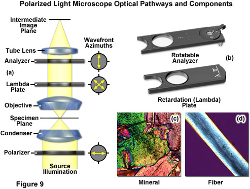
There are two polarizing elements in a polarizing microscope (see Figure 9). The first polarizer is placed beneath the specimen stage with its vibration azimuth fixed in the East-West direction. Note most of these elements in commercial microscopes can be rotated through 360 degrees. Another polarized (the analyzer), which is usually aligned with a vibration direction oriented North-South (but again rotatable on some microscopes), is placed above the objective and can be moved into and out of the light path as needed. When both the polarizer and analyzer are inserted into the optical path, their vibration azimuths are positioned at right angles to each other. In this configuration, the polarizer and analyzer are crossed, with no light passing through the optical system and a dark background present in the eyepieces (Figure 9(a)). Linearly polarized light waves are generated by polarizers that filter out a privileged plane from the statistical confusion of vibrational directions prevailing in natural light. The two orthogonal components of light (ordinary and extraordinary waves) travel at different speeds through the specimen and, as a result, observe different refractive indices, a phenomenon known as birefringence (derived from the terms double or bi refraction). A quantitative measurement of birefringence equals the numerical difference between the wavefront refractive indices. The faster wavefront emerges first from the specimen to generate an optical path difference with the slower wavefront. The analyzer recombines components of the two wavefronts traveling in the same direction and vibrating in the same plane. This polarizing element ensures that the two wavefronts have the same amplitude at the time of recombination for maximum contrast.
Recently, we have begun a study with only 50% coverage of our UbiGro Inner 600 in a greenhouse, focusing on the benefits of light diffusion. An initial reaction when looking at the picture above is that some areas of the canopy will be utilizing the optimal red-shifted spectrum from UbiGro, while other areas in the gap are receiving the directional sunlight. Perhaps surprisingly, this is not the case. When intensity and spectral data are recorded from various positions in the canopy, we find that the light levels are uniform and the spectrum is consistent whether measured under UbiGro or in the open space between the suspended strips of UbiGro. Even at 50% coverage, UbiGro is diffusing sunlight so effectively that the enhanced spectrum is the same all across the canopy, as is the PAR light level, showcasing the benefits of light diffusion in a greenhouse setting.
Bright field dark field
You can spend time scouring the web and see images from LED grow light companies with their lights above a canopy of cannabis. When you take a closer look and compare to that of HID and HPS, you will instantly notice how dark the plants look underneath the top canopy due to shadowing.
The wavefronts that have all been retarded to varying degrees by details in the specimen are superimposed in the intermediate image over the shifted and attenuated wavefronts where they amplify or attenuate each other (depending on the phase), forming the final phase contrast image observed in the eyepieces. These interference processes in the intermediate image create bright and dark areas of the various structures having refractive index (and/or thickness) variations in the specimen. Optimum contrast is created by selecting the correct retardation and attenuation values, which is a function of the optical properties of the phase ring in the objective aperture.
UbiGro brings this nanotechnology to greenhouses by not only altering the sun’s spectrum for optimal photosynthesis but also diffusing these photons in a greenhouse. UbiGro acts as a sun-activated layer of light in a greenhouse. It increases the proportion of the most photosynthetically active light in the spectrum (orange-red) as well as mixing up sunlight’s directionality to create a more diffuse light environment for plants.
In order for the beams to interfere, the vibrations of the beams of different path length must be brought into the same plane and axis. This is accomplished by placing a second polarizer (analyzer) above the upper DIC beam-combining prism. The light then proceeds toward the eyepiece where it can be observed as differences in intensity and color. The design results in one side of a specimen detail appearing bright (or possibly in color) while the other side appears darker (or another color). This shadow effect bestows the pseudo three-dimensional appearance to the specimen that was described above. There are numerous advantages in DIC microscopy as compared to phase contrast microscopy. With DIC, it is possible to make fuller use of the numerical aperture of the system and to provide optical staining (color). DIC also allows the microscope to achieve excellent resolution. Use of full objective aperture enables the microscopist to focus on a thin plane section of a thick specimen without confusing images from above or below the plane. Annoying halos, often encountered in phase contrast, are absent in DIC images, and suitable achromat and fluorite objectives can be used for this work. It is important to keep in mind, however, since DIC is based on polarized light principles, highly birefringent specimens or those embedded in birefringent materials should not be observed under DIC.
Tyler brings 15 years of experience in Greenhouse production and facility management of a wide range of crops in multiple states to the UbiGro team. Based in Salinas, California. “Being a fourth-generation farmer, I look to improve and empower the grower, and with UbiGro, we can do just that.”

However, to be clear I am by no means saying HID or HPS is the better light choice. I’ve covered this topic back in my days with one of the leading horticultural lighting companies in the world and I believe both technologies have their place in the industry. Some growers have definitely proven better yields and flavor profiles because of the possible spectral advantages of LEDs. I believe the LED manufacturers will soon combine the known light quality advantages of the spectrum while also utilizing light diffusion in combination for optimum performance.
First described by the Dutchman Frits Zernike in 1934, phase contrast earned its discoverer the Nobel Prize for physics in 1953 while revolutionizing basic biomedical research on living cells. The technique is ideal for thin unstained specimens (such as culture cells on glass), which are approximately 5 to 10 micrometers thick above the nucleus, but less than a micrometer thick at the periphery. Such specimens barely exhibit any light absorption in the visible portion of the spectrum and the human eye cannot detect them in brightfield and darkfield illumination. Phase contrast (as illustrated in Figure 1(b)) employs an optical mechanism to translate minute variations in phase into corresponding changes in amplitude, which can be visualized as differences in image contrast. The microscope must be equipped with a specialized condenser containing an annulus or a series of annuli matched to a set of objectives containing phase rings (designed Ph) in the rear focal plane (phase contrast objectives can also be used with fluorescence, but with a slight reduction in transmission). Phase contrast is an excellent method to increase contrast when viewing or imaging living cells in culture, but typically results in halos surrounding the outlines of edge features. These halos are optical artifacts that often reduce the visibility of boundary details. The technique is not useful for thick specimens (such as plant and animal tissue sections) because shifts in phase occur in regions removed from the focal plane that distort image detail. Furthermore, floating debris and other out-of-focus phase objects interfere with imaging adherent cells on coverslips.
The horticultural supplemental lighting industry has known the importance of light diffusion for greenhouse lighting and optimal plant growth for years. Have you ever noticed how HID lighting manufacturers all have reflectors that are “dimpled”? If you look at your shadow under an HID light with a dimpled reflector, you will see that your shadow under these luminaires looks blurry on the edges and is not very dark. This is because those dimples in the reflector are diffusing light. Conversely, if you look at your shadow under an LED light which does not utilize a reflector, you will see a darker shadow with defined edges because LEDs provide much more directional light.
Polarized light microscopy is a contrast-enhancing technique that dramatically improves the quality of an image acquired with birefringent materials when compared to other techniques such as brightfield and darkfield illumination, phase contrast, differential interference contrast, fluorescence, and Hoffman modulation contrast. Polarized light microscopes possess a high degree of sensitivity and can be used for both qualitative and quantitative studies targeted at a wide range of anisotropic specimens. Qualitative polarizing microscopy is quite popular in practice, however, the quantitative aspects of polarized light microscopy, which are principally applied in crystallography, represent a much more difficult subject that is primarily used by mineralogists, geologists, and chemists. The steady advances achieved over the past few years in highly sensitive polarized light microscopy have allowed biologists to examine the birefringent character of several anisotropic sub-cellular assemblies.
The methodology surrounding darkfield microscopy, although widely used for imaging transparent specimens throughout the 19th and 20th Centuries, is limited in use to physically isolated cells and organisms (as presented in Figure 1(e)). In this technique, the condenser directs a cone of light onto the specimen at high azimuths so that first-order wavefronts do not directly enter the objective front lens element. Light passing through the specimen is diffracted, reflected, and/or refracted by optical discontinuities (such as the cell membrane, nucleus, and internal organelles) enabling these faint rays to enter the objective. The specimen can then be visualized as a bright object on an otherwise black background. Unfortunately, light scattered by objects removed from the focal plane also contribute to the image, thus reducing contrast and obscuring specimen detail. This artifact is compounded by the fact that dust and debris in the imaging chamber also contribute significantly to the resulting image. Furthermore, thin adherent cells often suffer from very faint signal, whereas thick plant and animal tissues redirect too much light into the objective path, reducing the effectiveness of the technique.
While LEDs can reach high light levels with less power, they simply do not diffuse light or spread it uniformly on the canopy which can cause “hot spots” and uneven growth. This drawback is magnified by some of the higher output greenhouse-specific LEDs. Some LED companies even tout that their directional LEDs are optimal because HID reflectors “waste light by bouncing photons all over instead of concentrating them toward the canopy,” but as we just learned above, light diffusion is actually optimal for better photosynthesis – especially if you are utilizing lights for your sole light source in a room with reflective surfaces on the walls for optimal plant growth.
Another more recent study on light diffusion on cucumbers by Wageningen University stated: “Diffuse light has a positive influence on the production of cucumbers, especially during the summer, for greenhouse lighting. This positive effect can be explained by a change in light penetration into the crop and by an increased photosynthesis capacity, so that a crop like cucumber can utilize diffuse light better than direct light for optimal plant growth. In addition, diffuse roof material resulted in a lower crop temperature, especially higher in the crop which likely leads to more optimal conditions for photosynthesis in greenhouse lighting.” With a higher diffuse light component, not only were the plants able to photosynthesize better in the lower canopy, but better temperature uniformity also aided in overall plant health and optimal plant growth.
Conversely, when we see clouds in the sky that look white, this is because the water droplets in the sky are larger than the wavelengths of light so they capture and scatter all of the colors of the light spectrum, making them appear white. This type of natural light diffusion by clouds, referred to as “Mie Scattering” (named after German physicist Gustav Mie), is another example of light diffusion that can be mimicked in greenhouse lighting strategies to enhance plant growth by ensuring a balanced diffusion of light.
As my example above stated, sunlight is naturally diffused in our atmosphere. Plants have learned to utilize direct sunlight with their large canopy leaves as well as utilizing diffused light (or indirect light) in their leaves on lower branches. Plants are very efficient at utilizing light for photosynthesis at all levels in the canopy. As we continue to grow more crops in greenhouses and, to a lesser extent, indoors, there are more studies being done to show the importance of ensuring there is good diffusion in these facilities to optimize light quality for greenhouse lighting. This is crucial for achieving optimal plant growth, highlighting the importance of light diffusion technology in enhancing the efficiency of photosynthesis throughout the plant canopy.
We now understand that the optimized sun spectrum plus the light diffusion from UbiGro’s ‘layer of light’ are both contributing to increased photosynthesis, and therefore yields, for the grower. Both components of light quality – spectrum and light diffusion – are simultaneously improved by UbiGro, highlighting the significant benefits of light diffusion in enhancing greenhouse productivity.
Jim Gideon is an UbiGro Sales Manager, with over 25 years of greenhouse industry sales experience covering all of North America. Previously Jim has worked for Green Tek, Plazit-Polygal, Texel, Cherry Creek, and Nexus. He is based in Montgomery, AL, and Jim believes that “light is everything to the grower.”
Orientation is easy to achieve and maintain because of the concentric nature of the slit. Furthermore, because of the VAREL ring's location in the objective, VAREL and phase contrast rings can be combined in the same objective. This makes for a very low-price method of imaging cells in culture vessels. The problems of imaging in both traditional and routine tissue culture applications can be resolved with this method, it is a successful option for the examination of living objects (micromanipulation), and a range of structures with varying optical thickness are easily imaged with VAREL. Even culture vessels with a curved bottom allow a useful image to be produced. Phase contrast alone sometimes fails in such cases because a curved chamber base acts like a lens and impairs the superimposition of phase rings. A slider contains two of the mentioned sectors to allow illumination to be performed from the left or right, as required. This makes it possible to contrast cells even near the edges of the holes in microtiter plates.
The horticultural industry is always looking for new ways to optimize yields in a sustainable manner, with a focus on greenhouse lighting crops correctly and efficiently. When we discuss lighting for crops, we tend to define optimal plant growth lighting with three measurements: light intensity (or quantity), light duration (or photoperiod), and light quality (spectrum and distribution), including the benefits of light diffusion.
Eric Moody is UbiQD's Director of UbiGro Sales. Eric has more than 8 years of experience in the horticulture lighting industry, building relationships with greenhouse growers of all sizes and crops on optimal lighting for their growing operation, and most recently managed a North American sales team for PL Light Systems. Overall, Eric has been in sales leadership positions for more than 17 years. Eric brings with him a great understanding of the market and available technologies for growers, greenhouse facilities, and sales leadership.
As presented in Figure 2, very small differences exist between the refractive indices of the cells and their surrounding aqueous solutions and within the cells between the cytoplasm (Figure 2(b)) and the cell nucleus (Figure 2(c)). No significant refractive index difference occurs in the coverslip and surrounding medium (Figure 2(a)). Phase contrast makes these tiny differences visible by the use of optical manipulation as, for example, it translates them into differences in intensity that can be visually observed and recorded. The optical effect employed in this case consists of a shift of phase relationships between light wavefronts traveling through different portions of the specimen. During their journey through cell nuclei, cytoplasm, or water, the light waves are shifted (retarded) by small degrees, since these media have slightly different refractive indices (the higher the refractive index of a medium, the smaller the speed or velocity of light in the medium). As a result, a light wave that has passed through a cell nucleus lags behind the light waves that only had to pass through water (compare Figure 2(a) and Figure 2(c)). The amount of lag is called a phase shift. Before their entry into the specimen, the waves are still in phase (wavefronts beneath the coverslip), but this is no longer the case when they have passed through the various materials having different refractive indices. The amount of the phase shift depends on what media (refractive index) the waves have passed through on their paths, and how long the paths were through these media. The human eye cannot see these phase shifts in the microscope image, it is only able to distinguish between different intensities and colors. Therefore, the phase contrast technique uses optical tricks to translate phase shifts into grey values.
Eric Moody is UbiQD’s Director of UbiGro Sales. Eric has more than 6 years of experience in horticulture lighting industry, building relationships with greenhouse growers of all sizes and crops on optimal lighting for their growing operation, and most recently managed a North American sales team for PL Light Systems. Overall, Eric has been in sales leadership positions for more than 13 years. Eric brings with him a great understanding of the market and available technologies for growers, greenhouse facilities, and sales leadership. Reach Eric by phone at 541-490-6421 or by email at [email protected].
For more information about the capabilities of the UbiGro film or questions about this post, reach out to Eric Moody directly at [email protected].
One of the primary and favorite techniques used in all forms of optical microscopy for the past three centuries, brightfield illumination relies upon changes in light absorption, refractive index, or color for generating contrast. As light passes through the specimen, regions that alter the direction, speed, and/or spectrum of the wavefronts generate optical disparities (contrast) when the rays are gathered and focused by the objective. Resolution in a brightfield system depends on both the objective and condenser numerical apertures, and an immersion medium is required on both sides of the specimen (for numerical aperture combinations exceeding a value of 2.3). Digital cameras provide the wide dynamic range and spatial resolution required to capture the information present in a brightfield image. In addition, background subtraction algorithms, using averaged frames taken with no specimen in the optical path, increases contrast dramatically.
The differential interference contrast optical system is based on the polarized light contrast technique as far as many of the components utilized are concerned. DIC for a modern transmitted light microscope is different than that in reflected light because two birefringent prisms are used (see Figure 6), and the specimen's optical path difference is determined by the product of the refractive index difference (between the specimen and its surrounding medium) and the thickness (geometrical distance) traversed by a light beam between two points on the optical path (Figure 5). Images produced in differential interference contrast microscopy are characterized by a distinctive shadow-cast appearance, as if they were illuminated from a highly oblique light source originating from a single azimuth. Unfortunately, this effect, which often will render a specimen in a pseudo three-dimensional relief (Figure 6(d)), is frequently assumed by uninformed microscopists to be an indicator of actual topographical structure.
Plants have evolved for millions of years and are very efficient in utilizing the sun’s rays for photosynthesis. As we began cultivating plants for food, there was a long part of our history during which we only farmed and cultivated plants that grew naturally in our local environment. Today, as our population grows and concentrates in urban areas, there is an increasing demand to sustainably grow our food closer to our population centers. Greenhouse-controlled environment agriculture, with its advanced greenhouse lighting systems, is the best solution to serve this demand, ensuring optimal plant growth through precise light quality management.
Simple brightfield imaging, with the microscope properly adjusted for Köhler illumination, provides a limited degree of information about the cell outline, nuclear position, and the location of larger vesicles in unstained specimens. Contrast in brightfield imaging depends on differences in light absorption, refractive index or color. Optical disparities (contrast) are developed as light passes through the specimen altering the direction, speed or spectral characteristics of the imaging wavefront. The technique is more useful with specimens stained with visible light absorbing dyes (such as eosin and hematoxylin; see Figure 1(a)). However, the general lack of contrast in brightfield mode when examining unstained specimens renders this technique relatively useless for serious investigations of living cell structure.
Recent studies have shown that uniform distribution of light caused by diffusion, a key aspect of greenhouse lighting, can increase overall photosynthesis and production for optimal plant growth. A study in 2015 by the Chinese Academy of Agricultural Sciences stated: “Diffuse light improves spatial light distribution in the crop canopy, thereby stimulating crop photosynthesis; the more uniform horizontal light distribution within the canopy plays the most important role for this effect in greenhouse lighting. Diffuse light also lessens the variation of the temporal light distribution at any specific point in the canopy.” This study utilized glass greenhouse glazing with high light diffusion and maintained high light transmission for optimal plant growth.
Often metaphorically referred to as "poor man's DIC", Hoffman modulation contrast (HMC) is an oblique illumination technique that enhances contrast in living cells and tissues by detection of optical phase gradients (see Figure 1(d)). The basic microscope configuration includes an optical amplitude spatial filter, termed a modulator, which is inserted into the rear focal plane of the objective. Light intensity passing through the modulator varies above and below an average value, which by definition, is then said to be modulated. Coupled to the objective modulator is an off-axis slit aperture that is placed in the condenser front focal plane to direct oblique illumination towards the specimen. Unlike the phase plate in phase contrast microscopy, the Hoffman modulator is designed not to alter the phase of light passing through; rather it influences the principal zeroth order maxima to produce contrast. Hoffman modulation contrast is not hampered by the use of birefringent materials (such as plastic Petri dishes) in the optical pathway, so the technique is more useful for examining specimens in containers constructed with polymeric materials. On the downside, HMC produces a number of optical artifacts that render the technique somewhat less useful than phase contrast or DIC for live-cell imaging on glass coverslips.
Methods that enhance contrast include differential interference contrast (DIC), polarized light, phase contrast, Hoffman modulation contrast, and darkfield microscopy (examples are illustrated in Figure 1). Several of these techniques are limited by light originating in regions removed from the focal plane when imaging thicker plant and animal tissues, while polarized light requires birefringence (usually not present to a significant degree in animal cells) to generate contrast.
The phase stops must be centered after they have been installed in the condenser so that the image of the phase stop in the objective pupil corresponds exactly with the position of the phase ring in the beam path (see Figure 4(c)). Centering is performed using two small wrenches (or screwdrivers, depending upon the microscope model) on the turret disk of the condenser. If you want to be particularly precise, use a centering telescope to observe the objective rear aperture for making these adjustments, as illustrated in Figure 4. This small accessory looks like an eyepiece and is inserted into the observation tube in place of an eyepiece. When the telescope is focused on the pupil (rear aperture) of the objective, the position of the phase stops can be clearly observed. Again, look into the objective pupil and bring the bright image of the condenser phase stop into coincidence with the phase ring of the objective. This is clearly shown in Figure 4. In Figures 4(a) and 4(b), the phase stop is not aligned with the objective phase plate, while the stop and phase plate are in perfect congruence in Figure 4(c).
Dark field microscopy
Figure 6 illustrates the differential interference contrast beam path that is similar to that of polarized transmitted light. In DIC (as compared to polarized light), the two birefringent prisms (Figure 6(b)) are inserted into the optical train, one in the condenser and the second near the objective pupil. The condenser prism performs a vectorial decomposition of the previously linearly polarized light (Figure 6(c)) into two vibration directions that are perpendicularly polarized to each other, and laterally shifts these partial beams in such a way that a small lateral displacement of the wavefronts occurs where regions of thickness or refractive index vary. If the two partial beams now pass through exactly the same structures, no further path difference will occur in the specimen (Figure 5(a) and Figure 5(c)). However, if the two partial beams see slightly different conditions, each of them will experience a slightly difference pathlength that accompanies it on the remaining trip to the intermediate image plane (Figure 5(b)).
As Chief Product Officer at UbiQD, Dr. Matt Bergren leads the company’s product development efforts, sales, and product manufacturing, including the company’s first commercial agriculture product, UbiGro. He plays a critical role in continuing the company’s path of technology development and vision of powering product innovations in agriculture, clean energy, and security.
A major artifact of phase contrast imaging is the bright halos of light that appear on the borders surrounding the specimen. Halos occur in phase contrast microscopy because the circular phase-retarding (and neutral density) ring located in the objective phase plate also transmits a small degree of diffracted light from the specimen (it is not restricted to passing surround waves alone). The problem is compounded by the fact that the width of the non-diffracted light (zeroth-order) surround wavefront projected onto the phase plate by the condenser annulus is smaller than the actual width of the phase plate ring. Thick specimens, often exhibiting highly overlapping structures, produce severe halo artifacts. Therefore, phase contrast is a method that is only recommended for very thin specimens where several structures are not physically lying on top of each other. In a thick specimen, details may be blended into an image that, in the final analysis, is no longer legible.
Damon brings a wide range of experience in agriculture, materials science, spectroscopy, and small business. During his time in Prof. Angus Rockett’s research group at The University of Illinois at Urbana-Champaign (UIUC), Hebert authored a doctoral thesis and multiple papers on the materials science of CIGS semiconductor materials, which is closely related to the materials developed at UbiQD. He also served as a consultant to Nanosolar, a CIGS nanocrystal solar cell manufacturing company. Hebert has industry experience having co-founded Dr. Jolly’s, a leading cultivation and distribution operation in Bend, OR.
With the onslaught of so many LED supplemental lighting companies coming into the industry, there have been many studies conducted on light quality from the light spectrum, including the advantages of greenhouse light diffusion. What is the right spectrum of light for your crop, and at what stage of growth is each spectrum appropriate? For example, is a higher proportion of orange and red light in the spectrum beneficial for flowering and fruit production? Additionally, understanding the benefits of light diffusion in this context can enhance crop yield and health.
In phase contrast microscope configuration, the condenser aperture diaphragm is replaced by a phase stop (the size of which depends upon objective and condenser numerical aperture) that illuminates the specimen via the condenser optical components in a hollow cone of light fashion, as illustrated in Figure 3(a). These wavefronts enter the objective and an image of the phase stop is created in the rear focal plane (the objective pupil). Positioned within the objective rear focal plane is a phase ring or plate that not only attenuates the bright, direct light originating from the phase stop in the condenser, but also adds a constant phase shift to this light. If the specimen contains sub-structures that have mixed refractive indices, these entities guide the light from the direct waves into new paths (red dotted line in Figure 3(a)). Wavefronts diffracted by the specimen (in effect, those containing structural information) will not pass through the phase ring in the objective, meaning that they will not be attenuated or retarded. All of the wavefronts are ultimately recombined to form the intermediate image by the tube lens.
As discussed, the split DIC light beams enter and pass through the specimen where their wave paths are altered in accordance with the specimen's varying thickness, slopes, and refractive indices. These variations cause alterations in the wave path of both beams passing through areas of any specimen details lying close together. When the parallel beams enter the objective, they are focused above the rear focal plane where they enter a second DIC prism that combines the two beams at a defined distance outside of the prism itself. This removes the shear (distance between the waves) and the original path difference between the beam pairs. As a result of having traversed the specimen, the paths of the parallel beams are not of the same length (optical path difference) for differing areas of the specimen.
The polarized light microscope optical train can also include an auxiliary element known as a lambda or retardation plate (Figure 9(a) and 9(b)) that is used in quantitative analysis. In polarized light, this lambda plate converts contrast into colors. As in phase contrast, optical path differences give rise to colors, although this time with polarized light and birefringent material in the specimen. The path differences generated leads to an extinction of certain wavelengths in the light through interference (only certain colors remain from the white light and create beautiful, colored pictures). Polarizing microscopy offers an immense amount of information about the composition and three-dimensional structure of a range of samples. Practically unlimited in its scope, the technique can reveal information about thermal history and the strains to which a specimen was subjected during formation. Valuable in manufacturing and research, polarizing microscopy is relatively inexpensive and an accessible research and quality control tool that can provide information unavailable with any other technique.
Erin E. Wilson and Michael W. Davidson - National High Magnetic Field Laboratory, 1800 East Paul Dirac Dr., The Florida State University, Tallahassee, Florida, 32310.
He serves as the principal investigator for UbiQD’s contract with NASA, focused on tailoring the solar spectrum for enhanced crop production for space missions. Dr. Bergren’s leadership experience includes serving on the board of directors for the New Mexico Energy Manufacturing Institute, focused on job creation in New Mexico’s energy, and related manufacturing community.
The appropriate arrangement for polarized light imaging is relatively easy to implement on virtually any microscope. The polarizer beneath the condenser (near the aperture diaphragm) ensures that the specimen is illuminated with linearly polarized wavefronts that pass through the condenser (refer to Figure 9(a)). The analyzer (a second polarizer), which is oriented with the azimuth arranged at an angle of 90 degrees to that of the polarizer, is located behind the objective. The tube lens forms the intermediate image, which is projected through the eyepieces or onto a camera imaging plane. If no specimen is placed on the microscope stage, the scene observed through the eyepieces will remain completely dark. When illuminated, many specimens turn the vibration direction of the polarized light out of the plane produced by the polarizer. Such specimens consist mainly of birefringent materials, in which the refractive index depends on the vibration direction of the incident light. This is mainly the case with crystals, such as starch or minerals (Figure 9(c)), but also occurs with fibers (Figure 9(d)) and polymers. If such materials are viewed under the polarization microscope between the crossed polarizer and the analyzer, bright areas can be seen in the image because light is partially transmitted by the analyzer.
Some LED manufacturers are already embracing this truth as stated by Osram in the following HortiDaily article: “Current LED fixtures often have a Lambertian primary lens and no secondary optic, or a simple glass cover, which lead to hotspots with a high concentration of light directly under the luminaire. The result is areas with different intensities of illumination, causing inconsistent yields.” LED companies like Osram are looking for and developing ways to better diffuse light for this reason.
Dr. Michael Burrows is UbiQd’s Vice President of Business Development. His educational background includes a Materials Science doctorate from the University of Delaware and an MBA from Duke University Fuqua School of Business. His career has specialized in the commercialization of novel electronic materials in venture-run programs for different industries including solar, biosensors, and the automotive industry. In both start-up and corporate environments, he has extensive experience in global market development, foraging supply chain partnerships, productization, and brand building. He is currently leading UbiQD’s partnership efforts in luminescent greenhouse technology, smart windows, and security ventures.
Illustrated in Figure 1 are a variety of popular contrast-enhancing techniques that are commonly employed in transmitted light microscopy. The thin tissue section in Figure 1(a) reveals a human basal cell carcinoma stained with eosin and hematoxylin to generate color contrast in brightfield imaging mode. Figure 1(b) shows living HeLa cells in a plastic tissue culture vessel imaged with phase contrast. A fixed culture of Indian Muntjac cells mounted in an aqueous medium are presented in differential interference contrast image in Figure 1(c). A fresh tissue section of mouse heart muscle bathed in aqueous saline solution is displayed in the Figure 1(d) panel, where contrast is generated using Hoffman modulation (or ZEISS VAREL) contrast, an oblique illumination technique. The brilliant bright-on-dark contrast observed with darkfield illumination is shown in Figure 1(e) using an Obelia hydroid specimen. Finally, rabbit skeletal muscle fibers (Figure 1(f)) are among the biological specimens that are birefringent and demonstrate contrast in polarized light.
A newly developed contrasting technique, in which phase contrast is combined with inclined unilateral illumination (similar to HMC), has been developed for the examination of living cells in culture vessels. An additional stop shaped like a ring sector is used on the illumination side, permitting unilateral inclined illumination. Three illumination modes, unilateral darkfield, VAREL (variable relief) contrast, and inclined brightfield (similar to oblique illumination or HMC) are set by shifting the stop in the radial direction from the outside to the inside (see Figure 7) and a segment of a matching annulus is moved into position. This slit directs the source illumination to pass through a second ring of high absorption on the objective aperture's periphery, which suppresses its intensity by an amount dependent upon the density of the outer ring. The diffracted orders of light pass through the objective without being suppressed by the VAREL ring. You can also manipulate the position of the slit if you want to vary the extent the source illumination is suppressed.
Simply put, light diffusion in the context of greenhouse lighting is the scattering of light, which is crucial for optimal plant growth. It involves photons bouncing around in all directions, ensuring even exposure to plants. The opposite of diffuse light is directional light where photons travel all in the same direction, which can be less effective in a greenhouse setting aimed at promoting plant health. Think about standing under a large outdoor shelter when the sun is highest in the sky. If there was no diffusion of light at all, it would be very bright outside the shelter but totally dark under the shade of it. The reason we can still see well in the shade, and why plants can thrive under light diffusion, is the natural diffusion of sunlight by our atmosphere, and that sunlight bounces off objects and scatters into the shelter, mimicking an optimal light diffusion scenario for plant growth in greenhouses.


 Ms.Cici
 8618319014500