
What Is the Field of View (FOV) in an Action Camera? - fov camera
Enter your email address below to receive the presentation slides. In the future, weâll share you very few emails when we have new tutorial release, development updates, valuable toolkits and technical guidance . You can unsubscribe at any time by clicking the link at the bottom of every email. Weâll never share your information.
Phonecamera sensor size
Note: because the simulation is just being used for the mode solver, we can safely ignore the warning about lack of sources.
Image sensor format, sometimes referred to as “optical format” or “sensor size”, refers to the shape and size of the image sensor in a digital camera. The image sensor format is usually listed in the camera’s specifications and is required knowledge for selecting appropriate macro lenses and microscope adapters. There are two ways image sensor format can be described: inch-based format and APS format.
Example Library / Passive Photonic Integrated Circuit Components / Uniform grating coupler
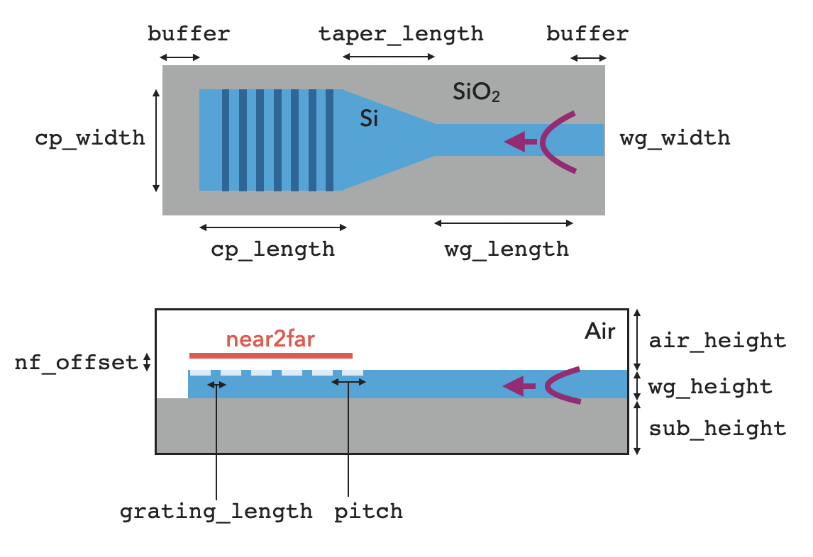
A basic schematic of the design is shown below. The simulation is about 19um x 4um x 5um with a wavelength of 1.55um and takes about 1 minute to simulate 10,000 time steps.
Nikoncamera sensor size
Laser Products Industries | 840 abonnés sur LinkedIn. LPI develops laser measuring equipment and technology solutions for countertop and other industries.
We can also run the coupler in the opposite way, injecting a Gaussian beam from above and monitoring the transmission into the waveguide. We will use the measured angle rather than the design angle to see the highest in-coupling efficiency that we can obtain.
Sensor sizechart
The back focal length and diameters of M12 / S Mount lenses are frequently incompatible with CS and C Mount cameras, resulting in a lens-to-mount combination ...
Apr 27, 2019 — "When you look through a lens, the image is being spread out", so does this mean when the object is enlarged its brightness decrease since the ...
Camera sensor sizecomparison
If you are new to the finite-difference time-domain (FDTD) method, we highly recommend going through our FDTD101 tutorials.
2011912 — So while MTF is widely accepted as an important factor with lens selection, it is often not considered with the sensor/camera selection. MTF ...
Find caf2 and related products for scientific research at MilliporeSigma.
1/2.3sensor sizevs 1 inch
With a microscope, a relay lens system replaces the single lens; an objective and an eyepiece work in tandem to project the image of the object onto the eye, or ...
The agreement between the target angle and the actual emission angle of the coupler is good. The small difference comes from the fact that the design is very sensitive to the value of the effective index that we use in the coupler region, and that value depends on which waveguide height we pick in that region: the one with the grating comb, or without. In our setup, we used a thickness that is at the mid-point, but this is a heuristic choice which results in the small final mismatch in angles observed here.
The inch-based image sensor format originated in the 1950’s and stems from the physical size of the vidicon tube sensor used in cameras at that time. The outside diameter of the vidicon tube was equal to 1” and the imaging area of the tube was 16mm diagonal. The sensor was commonly referred to as a 1” sensor and shortly thereafter it was commonly known that a 1” sensor had an imaging diagonal of 16mm. This resulted in the seemingly odd image sensor inch format: 1” = 16mm. This format standard survived the conversion to solid state image sensors (CCD and CMOS sensors) even though the corresponding vidicon tube was gone. The 1” = 16mm conversion factor allows the quick calculation of the modern day inch format sensor diagonals seen in the table below.
The formula that it implements is FOV = 2 arctan (x / (2 f)), where x is the diagonal of the film. The FOV is measured across the frame's diagonal, and is ...
Camera sensor sizecalculator
The coupler has close to 5% in-coupling efficiency, and we did not put any effort into optimizing it beyond just defining the grating pitch to target the correct angle!
iPhonecamera sensor size
Leaning in · Identify (and preferably hold!) the object you want to examine · Bring your magnifying glass to your dominant eye, maybe an inch or two away at ...
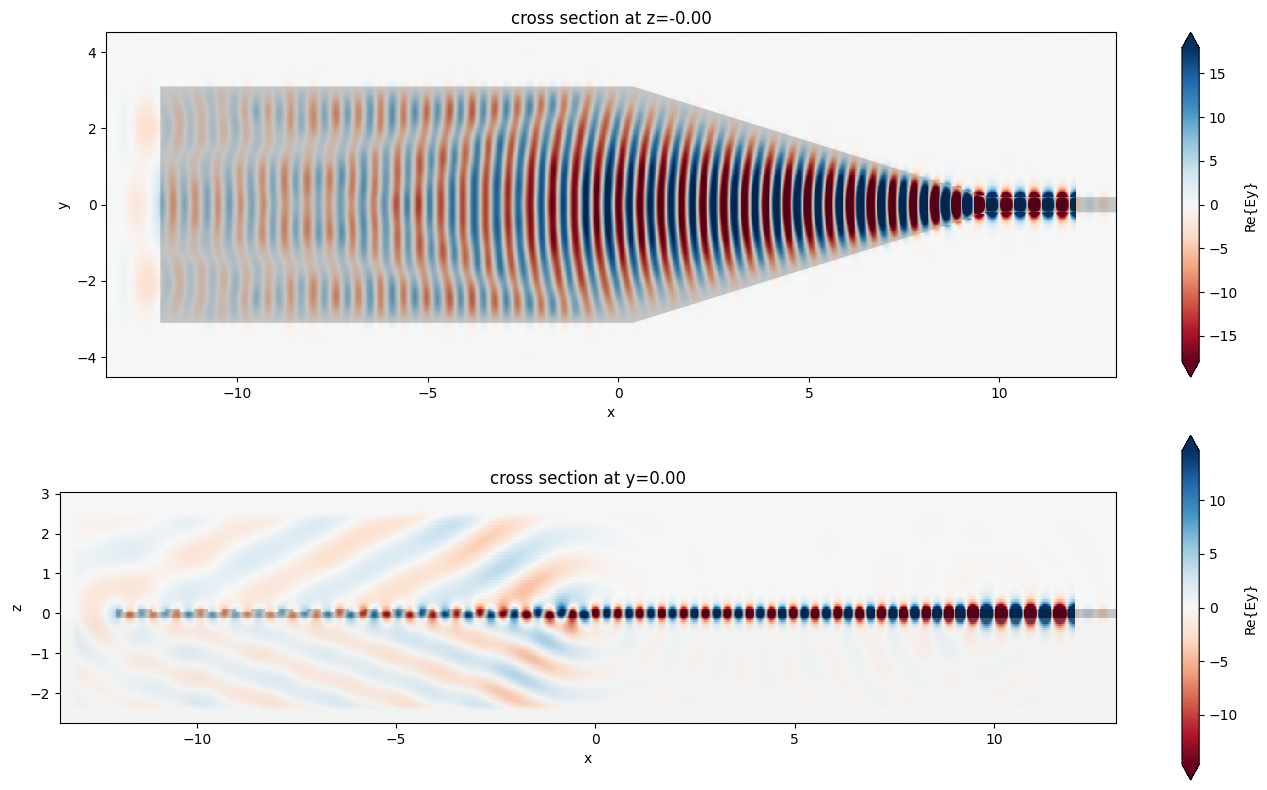
In the simulation, we inject a modal source into the waveguide and propagate it towards the grating structure. The radiation from the grating coupler is then measured with a near field monitor and we use a far field projection to inspect the angular dependence of the radiation.
UV glues are bonded under ultra violet rays or strong sun light. bonding properties of UV glue used for adhesion between glass to glass.
Now we use the Tidy3D's FieldProjector to compute the anglular dependence of the far field scattering based on the near field monitor.
Camera sensor sizein inches
To determine the pitch of the waveguide for a given design angle, we need to compute the effective index of the waveguide mode being coupled into. For this, we set up a simple simulation of the coupler region and use the mode solver to get the effective index. We will not run this simulation, we just add a ModeMonitor object in order to construct and run the mode solver below, and get the effective index of the wide-waveguide region.
In addition to the uniform grating coupler modeled here, we also studied a focusing apodized grating coupler and an inverse designed compact grating coupler in our case studies. Besides grating couplers, we have also investigated an inverse taper edge coupler.

When image sensors exceed 4/3”, the APS (Advanced Photo System) format standard is used to describe the size of sensors instead of the inch-based format. The APS measurement system originates in 35 mm SLR & DSLR camera standards. Common APS formats are listed in the table below.
The wave plate produces its own optical path difference. When the light passes first through the specimen and then the accessory plate, the OPDs of the wave ...


 Ms.Cici
 8618319014500