
Velvet Steel Health & Performance - steel and velvet
It is important to note that the OTF relations above are, by their basic concept, valid only for incoherent light. Formal derivation states that this type of pattern in coherent light would be reproduced without any distortions in amplitude or phase, i.e. with 100% contrast transfer, with the sudden drop to zero at the cutoff frequency 2λ/D (coherent transfer function). As above relations show, MTF does not include possible lateral shift of intensity pattern in any way. This is not by choice, rather by the inherent property of MTF defined as the modulus (magnitude) of contrast transfer as a function of spatial frequency, with every spatial frequency treated as an isolated contributor to the function. Thus, lateral shift of the pattern is no factor, only the contrast level is recorded. MTF alone shows the efficiency of contrast transfer from the object to its image with zero intensity phase shift, for a single orientation in the aberrated image, normally that along the axis of aberration. However, 180° (π radians) phase shift, which can be caused by large amounts of aberrations, will result in contrast reversal, i.e. switch of bright and dark areas in the image vs. object. For instance, such image of F, in addition to it being distorted by the large level of aberration, could make it unrecognizable, even if contrast needed for detection is there. Hence, the OTF phase factor is potentially important factor in predicting image quality, but only in the presence of large aberrations, well above the level found near axis in optical telescopes (for instance, contrast reversal due to primary spherical occurs at near 2λ P-V wavefront error). Similar to MTF is the contrast transfer function (CTF), the difference being that the latter describes impulse response (i.e. contrast change in the image vs. object) based on an object that is a continuous square wave intensity distribution, in effect a continuum of bright and dark lines with even intensity distribution over them. Some additional basic aspects of the OTF/MTF are given below. INSET A illustrates characteristic form of the MTF, showing contrast drop as a function of spatial frequency ν for brightly illuminated object with high inherent contrast, as well as the effects of change in illumination/contrast level. For comparison, graph also shows the CTF. INSET B illustrates the effect of phase shift, INSET C shows OTF expanded to include radial PSF dimension and its effect, and INSET D illustrates polychromatic MTF. INSET A: TOP LEFT: Standardized MTF object form is a continuum of parallel, equally spaced bright contrasty lines on dark background, with irradiance modulation defined as infinite sinusoidal distribution. The line width, equaling that of the dark/light pair, is inversely proportional to the spatial frequency ν, normalized to 1 at the cutoff frequency D/λ cycles per radian (the inverse of the angular limit to resolution λ/D in radians, D being the aperture diameter), where image contrast drops to zero (linear cutoff frequency is the inverse of the linear limit to resolution λF, or 1/λF in lines per mm, for λ in mm). This form of intensity distribution can be represented as periodic sinusoidal wave, with the contrast determined by the relative intensity of its maxima vs. minima. Image of this pattern has the relative intensity and contrast dampened due to the effect of diffraction, whether without or with aberrations present, At any given frequency, MTF is a ratio of the output (image) to input (object) modulation amplitude. Mathematically, it is Fourier transform of the system's PSF (more specifically, it is an integrated sum of the PSFs for every point over its intensity distribution profile, i.e. convolution of object's Gaussian image and aperture's PSF). At the limit of resolution for aberration-free aperture, the line width is nearly equal to the aperture's FWHM. TOP RIGHT: The modulation transfer function - MTF - for clear aberration-free aperture (P) is the ultimate limit to the overall contrast and resolution set by diffraction for this type of object. Normalized to 1, it equals the relative overlapping area of two circles of unit diameter (graphic representation of pupil autocorrelation), at a center separation ν, the normalized spatial frequency (top right, yellow overlap area for ν~0.3). MTF in aberrated aperture (A, 1/4 wave P-V of spherical aberration) is lower than P over the entire range of frequencies. The standard MTF plot is non-linear, in that any given linear change of contrast is proportional to the normalized frequency (i.e. same linear change at, say, 0.5 frequency is about twice the relative change at 0.25 frequency). The relative contrast (RC) shows contrast differential between the two more clearly, directly comparable, in units of the perfect aperture contrast level normalized to 1 over the frequency range. The low-contrast thresholds for bright (LCB) and dim (LCD) details, is an informal, but useful addition by Rutten and Venrooij. It indicates that the approximate cutoff levels for typical low-contrast details - about 10% inherent contrast - requires higher minimum contrast at the resolution limit than the standard bright, contrasty MTF pattern. As a consequence, their cutoff frequencies are lower than for high-contrast details. The original plots are constructed with respect to a perfect aperture transfer line starting at 0.1 contrast for zero frequency, decreasing toward zero at the regular cutoff frequency, with the limit to resolution determined by the minimum contrast required by the eye, approximated at 5% for the bright and 2-3 times as much for dim details, both steadily increasing from low toward high frequencies; the LCB and LCD lines above are based on these plots, only with the contrast at zero frequency normalized to 1, i.e stretched out tenfold vertically. The two lower threshold lines are for bright and dim details with 100% inherent contrast. As shown, the approximate resolution limit is 1/2 and 1/7 of the standard MTF cutoff frequency for bright and dim low-contrast objects, respectively. For contrasty dim details (HCD, High-Contrast-Dim), the approximate minimum contrast level HCD indicates the limiting resolution of about 0.7 frequency. It is somewhat better for contrasty bright detail (HCB) - near 0.9 frequency - but the resolution limit would require the maximum contrast. Again, these are only general approximations, and may be inaccurate, particularly toward cutoff frequency, since the actual minimum contrast required by eye increases exponentially close to the limit of resolution (FIG. 236C). Note that different patterns of intensity distribution have different contrast transfer; for instance, periodic square wave (i.e. pattern of sharply defined dark and bright lines) will have contrast transfer higher at all frequencies either in aberration-free aperture (solid blue line), or for any given level of aberration, as the CTF for clear aberration-free aperture (blue plot) indicates. However, the relative change in contrast transfer due to aberrations and/or obstructions are generally similar for MTF and CTF. INSET B: As mentioned, the complete OTF describes both, contrast transfer, or modultion (MTF), and phase transfer from object to its image. Phase transfer can only occur if diffraction peak is displaced away from the intersection of chief ray (one that passes through the center of the aperture stop) and image plane. That causes lateral shift of the MTF bar pattern, as illustrated below for coma (left) and defocus (right). Of all conic aberration forms, only coma induces phase shift due to its asymmetric PSF, except when its axis of aberration ( i.e. axis of symmetry for the geometric blur) is parallel with MTF bars. Other conic aberrations can also induce phase shift, but as a consequence of the change in PSF intensity distribution. Shown are only coma PSFs for a few selected points on the object (MTF pattern subjected to imaging) are shown, but the actual calculation includes PSFs from all points of the object-pattern. The combined amplitude they produce at every point in the image plane determines the intensity pattern of the image-pattern, i.e. its contrast transfer characteristics (note that PSFs shown are independent, not a convolution of the Gaussian image, thus the image pattern is only an illustration). The PSF peak shift for λ/2 wave P-V of primary coma (0.088 wave RMS) is λF, which is on this illustration about 1/7.5 of the full phase of the sinusoidal pattern (indicating the corresponding pattern frequency as 7.5 times the λF cutoff frequency, or ~0.13 , resulting in 2π/7.5 phase shift of the MTF pattern. Phase shift does not affect contrast transfer, which is determined by the combined wave amplitude itself, which is MTF domain. Since the PSF shift, when present, has constant value, the corresponding phase shift varies across the range of frequencies, and can be plotted as a separate PTF. At right, shown is the effect of 1 wave P-V of defocus on the image of an object that is not the standard MTF pattern, but one in which bar width is oriented horizontally, with the line width changing continuously according to the spatial frequency. Top image (A) is aberration-free, and bottom (B) defocused one. If the aberration is large enough - in the case of defocus ~0.9 wave P-V or larger - image of such object will show contrast reversal - where bright lines become dark and vice versa - indicated by the OTF, but not the MTF. The reason was immediately apparent from the PSF intensity distribution for 1 wave of defocus, developing dark circle (minima) at the center of the pattern. Hence, MTF does provide information on contrast transfer, but not on the image itself. To reconstruct the image, we need OTF. This, however. may have significance only with large aberrations, generally about 1 wave P-V and larger (a few more examples at ). OTF for smaller aberrations does not fall below zero, thus there is no contrast reversal to affect image. As plot at right show, the standard MTF output by OSLO (dashed) does not equal the absolute value of OTF, indicating that MTF plot may vary somewhat depending on the algorithm applied. If defined as the absolute value of OTF magnitude, MTF should continue through the red plot section. INSET C: In addition to phase shift, if PSF intensity is varying radially it will also cause different contrast transfer for different orientations of the PSF relative to MTF pattern. A complete MTF integral has radial component, thus it integrates for all orientations of the PSF relative to the line pattern. Graphically, it is represented by a volume figure, formed by continuous change of the integration angle (i.e. pattern orientation) through a full circle, or 2π radians (right). This volume may be looked at as a total contrast, transfer. For radially symmetrical aberrations, like spherical or defocus, there is no variation in contrast transfer with orientation, and it is fully represented by any single orientation, i.e. 2-D MTF. For radially asymmetrical aberrations, like coma or astigmatism, the transfer, hence also the MTF volume cross section profile, changes with the orientation, forming rotationally asymmetrical 3-D figure. The default representation is often to show MTF for sagittal (perpendicular to MTF bar orientation) and tangential (along bar orientation) PSF orientation. This works well with coma, where it assesses the two limiting effects, the minimum (the latter) and maximum (former), giving a good idea of the average effect on contrast transfer. With astigmatism, however, which at the minimum variance focus causes a cross-like PSF deformation, with 0 (π) and π/2 (3π/2) PSF rotation producing the same effect, while the maximum effect on MTF contrast transfer is for π/4 (+π) PSF rotations. Contrast transfer for all PSF orientations also can be azimuthally averaged, giving mean contrast transfer for the aberration. INSET D: Note that the graph on top represents monochromatic MTF (as indicated by the cutoff frequency 1/λF). Polychromatic MTF cutoff frequency - and to a slight extent, the overall shape - is determined by the combined PSF intensity distribution within the wavelength range. As large inset at right illustrates, while PSF for individual wavelengths differ significantly at the ends of given spectral range (first minima being at 1.22λF), when combined they nearly offset around the central wavelength's PSF. Actual PSFs for different wavelengths also normally differ in their intensity, both emitted by object and perceived by eye, which may affect contrast transfer by giving to it bias toward the wavelength of maximum intensity, since the intensity distribution loses the symmetry around central wavelength). There is little difference between centered monochromatic (green) and full-range polychromatic PSF (black), thus also MTF, regardless of the sensitivity mode. The PSF differ mainly in the ring area (photopic vs. even spectrum, small inset), and with MTF it is limited to the value of cutoff frequency, which is for polychromatic light determined by that for the shortest wavelength. This is based on the formalism describing polychromatic contrast transfer as the average sum of the transfer c for given frequency ν at each of i wavelengths, MTF(ν)=Σc(ν)i/i. As a result, long and short wavelengths nearly offset each other for the most of frequency range, with the resulting polychromatic MTF for the range gravitating toward that of the mid-wavelength; some residual contrast transfer extends beyond that for the central wavelength, not significantly influenced by eye sensitivity factor. While the nominal cutoff frequency for polychromatic MTF equals that of the shortest wavelength, it actual contrast transfer is much closer to that of the central wavelength. For aberration-free clear aperture, the MTF is given by MTF=(2/π)[cos-1ν-ν(1-ν2)0.5]. It can be also expressed as: with the angle α in degrees found from cos(α)=ν (for software use, the angle obtained from arccos(ν) is in radians, hence needs to be multiplied with 180/π for degrees; the corresponding form for the first factor is then 2arccoss(ν)/π). Graphically, MTF contrast transfer equals the relative overlapping area of two identical circles, in units of the circle area (FIG. 62, top right), with the circle diameter normalized to 1, and the center separation s=ν varying from 0 when the circles are coinciding (ν=0), to 1 when only touching (cutoff frequency ν=1). MTF IN A PERFECT UNOBSTRUCTED APERTURE MTF frequency 0.0 0.1 0.2 0.3 0.4 0.5 0.6 0.7 0.8 0.9 1.0 Contrast transfer 1.0000 0.8681 0.7483 0.6310 0.5138 0.4008 0.2983 0.1957 0.1069 0.0414 0.0000 Similarly, the normalized MTF for reduced aperture (still of unit diameter, with v=0 when the two circles are touching, smaller inside the larger), equals the overlapping area with the smaller circle appropriately reduced in diameter, with overlapping area being in units of the smaller circle area. The actual range of resolvable frequencies of a smaller aperture is in proportion to the aperture reduction factor. In terms of MTF, CTF is given as CTF=(4/π)[MTF
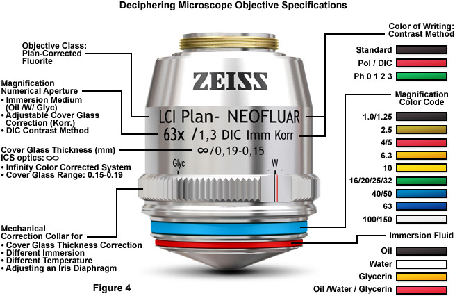
Most of the high-performance objectives feature spring mounts (see Figure 1) to protect the specimen, and many of the immersion objectives have nosepieces that can be snapped into the top position of their spring mount to enable the easy application of immersion fluids. The glass selected for objective fabrication must have suitable refractive index and dispersion, homogeneity, absence of strain, high chemical resistance, low thermal expansion, resistance to climatic changes, and high light transmission through the near-ultraviolet, visible, and near-infrared portions of the spectrum. In terms of how the various correction factors for objectives are categorized, the achromats have good color correction in two wavelengths, feature relatively flat fields in the center of the image, but require refocusing to observe details in the peripheral areas. Achromats are produced in versions designed for polarized light and phase contrast, but not fluorescence or differential interference contrast (DIC). Plan and epi-plan objectives are improved achromat versions with excellent flatness of field up to diameters of 24 millimeters or more. In addition, reflected light achromat objectives exhibit excellent contrast and a variety of working distances. The specifications required to identify objectives (see Figure 4) are usually inscribed on the decorative barrel protecting the internal lens elements.
While some of the microscope optical components act as image-forming elements, others serve to produce various modifications to illumination of the specimen and also have filtering or transforming functions. Components involved in formation of images by the microscope optical train are the collector lens (positioned within or near the illuminator), condenser, objective, eyepiece (or ocular), and the refractive elements of the human eye or the camera lens. Although some of these components are not typically thought of as imaging components, their imaging properties are paramount in determining the final quality of the microscope image.
MTFOptics
Eyepieces work in combination with microscope objectives to further magnify the intermediate image so that specimen details can be observed. Oculars is an alternative name for eyepieces that has been widely used in the literature. The best results in microscopy require that objectives be used in combination with eyepieces that are appropriate to the correction and type of objective. The basic anatomy of a typical modern eyepiece is illustrated in Figure 3. Inscriptions on the side of the eyepiece describe its particular characteristics and function. There are two major types of eyepieces that are grouped according to lens and diaphragm arrangement: the negative eyepieces with an internal diaphragm and positive eyepieces that have a diaphragm below the lenses of the eyepiece. Negative eyepieces have two lenses: the upper lens, which is closest to the observer's eye, is called the eye-lens and the lower lens (beneath the diaphragm) is often termed the field lens. In their simplest form, both lenses are plano-convex, with convex sides facing the specimen. Approximately mid-way between these lenses there is a fixed circular opening or internal diaphragm which, by its size, defines the circular field of view that is observed in looking into the microscope.
Graph below illustrates normalized frequency implications with respect to MTF pattern characteristics. Since cutoff frequency is given in frequency form, as D/λ, the inverse of the actual resolution, the lower frequency, the wider pattern. With the resolution at cutoff frequency, λ/D, being 2.44 times smaller than the angular Airy disc diameter (given by 2.44λF/f, f being the focal length, hence equaling 2.44λ/D), the pattern width is proportional to the inverse of normalized frequency: it is twice wider than at the cutoff at 0.5 frequency, five times at 0.2 frequency, and so on. To express it in Airy disc diameters, it only needs to be divided by 2.44 (so it will be 2/2.44=0.82 Airy disc diameters wide at 0.5 frequency). It is important to understand that the MTF graph, such as the one above, does not set absolute values for the contrast drop, or limit to resolution. Both are strictly applicable only to the particular MTF object form used for its calculation: a sinusoidal pattern of bright lines on dark background, λF/2ν wide linearly, F being the focal ratio f/D (i.e. linear width of the bright line at resolution limit is λF/2, or nearly one fifth of Airy disc diameter). Actual contrast drop-off and limiting resolution will vary with the specific properties of details observed, background, and peculiarities of eye perception, or detector properties. For non-continuous patterns, sinusoidal, square-wave, or others, contrast transfer will generally increase with the reduction in the number of lines (FIG. 103). One example is the resolution threshold for low-contrast MTF-like planetary details which is, according to the LCB threshold level in FIG. 100, approximately half of that for brightly illuminated contrasty object. Another is a dark line on light background, which can be detected at an angular width several times smaller than the angular diffraction resolution limit for point-images of ~λ/D radians, because it is the Edge Spread Function, not the PSF, that is applicable in determining its diffraction intensity distribution. An actual object that comes very close to the standardized MTF scenario is a pair of nearly equally bright stars at the optimum brightness level. Resolution-wise, the MTF limiting resolution (cutoff frequency) is nearly identical to the empirical Dawes' limit in double star observing. However, for pairs farther from the optimum brightness level, or, especially, pairs with significant difference in brightness, the resolution limit is lower, or much lower. Still, despite the MTF being standardized to a single object form sample and brightness level, it is considered to be a reliable general indicator of the effect of wavefront aberrations - or any other factor affecting wave interference in the focal zone - on image quality. As mentioned, given relatively low RMS wavefront level of any aberration will result in near-identical overall contrast loss, but the specifics will vary somewhat. FIG. 101 illustrates variations in the aberrated PSF (left) and MTF (right) for common wavefront aberrations of 1/13.4 and 1/6.7 wave RMS (graphs generated by Aberrator freeware, Cor Berrevoets). FIGURE 101: PSF and MTF plots for clear aberration-free aperture (black), and aberrated (red) at the 0.80 Strehl level, and that wavefront error doubled. DEFOCUS: 1/4 and 1/2 wave P-V. Doubling the error halves the peak PSF intensity (Strehl), but the average contrast loss is three times greater (20% vs. 60%, given as a ratio number by the differential between the Strehl and 1). Note that the Strehl for 1/4 wave WFE of defocus is slightly higher than 0.80. PRIMARY SPHERICAL ABERRATION: 1/4 wave and 1/2 wave P-V errors have nearly identical effect on the PSF maximum as with defocus, but the more widely spread energy causes more of contrast loss at the lower frequencies, while the smaller central maxima results in somewhat better transfer at mid-to-high frequencies. The transfer is again inferior near the cutoff due to the smaller bright core with defocus. Being close to zero, the cutoff frequency for 1/2 wave P-V is about 20% lower in field conditions. PRIMARY COMA: 0.42 and 0.84 wave P-V have similar effect on the PSF peak value as 1/4 and 1/2 wave P-V of defocus or primary spherical. However, the actual contrast transfer varies significantly with the orientation of the asymmetrical aberrated pattern relative to MTF bars. It is the worst when the blur length is perpendicular to the bars (red), and the best when blur length has the same orientation (green). MTF plots hitting zero contrast near the cutoff and bouncing after, indicate contrast reversal. PRIMARY ASTIGMATISM: The effect of 0.37 and 0.74 wave P-V is similar to 1/4 and 1/2 wave of defocus in that the energy spread out of the Airy disc is mostly contained closer to central maxima, resulting in less of contrast loss at low frequencies. Unlike defocus, does not change radial symmetry of PSF, astigmatism gives to it cross-like shape which, similarly to coma's asymmetry, gives the best contrast transfer when cross orientation is identical to that of the bars (green) and the worst when it is at 45° angle. TURNED EDGE: 2.5 waves P-V is needed that turned edge starting at 95% the radius to lower the Strehl to 0.80. Lost energy is evenly spread wide out (the abrupt initial contrast loss ending at about 1/40 frequency indicates the radius of this spread as 40 times the cutoff frequency, or 40λF - over 30 times the Airy disc radius). Odd but expected TE property - due to the relatively small affected area (the RMS for 0.80 Strehl is whooping 0.28 wave) - is that increasing the aberration does almost no additional damage. ROUGHNESS: ~1/14 and ~1/7 wave RMS of roughness producing asymmetric PSF pattern, thus having contrast transfer vary with its orientation relative to MTF bars. Due to the random nature of the aberration, the P-V wavefront error can vary significantly for any given RMS/Strehl level. IHere, the P-V error ranges from -0.169 (blue speck on the wavefront map) to 0.374, and -345 to 0.745, respectively. RMS error also may not be as reliably related to the Strehl as with most other aberrations. PINCHING: 0.37 and 0.74 wave P-V of wavefront deformation caused by edge pinching at a three 120° separated points has the typical 3-sided symmetry (trefoil). the aberration is radially asymmetric, causing the contrast transfer to vary between the maximum (red, for zero, 120° and 240° orientation angle) and minimum (60°, 180° and 300° orientation). Other forms do occur, with or without some form of symmetry. About 30% of the frequency range toward high end shows contrast reversal. TUBE CURRENTS: 3/4 and 1.5 wave P-V wavefront error caused by tube currents affecting end 30% of the wavefront radius. Energy spreads mainly in the direction of wavefront deformation. Similarly to the TE, the RMS error (0.106 and 0.212, respectively) is disproportionally large vs. Strehl, and doubling the error has relatively small effect. Contrast transfer is the worst when the energy spreads orthogonally to MTF bars; for the aberrated energy spread having the same orientation as MTF bars is perfect (green). SEEING ERROR: Averaged PSF/MTF effect of ~1/14 and ~1/7 wave RMS of atmospheric turbulence. The P-V error can vary substantially (here is 0.43 and 0.86 wave, respectively). Seeing error fluctuates constantly around the average, as do the corresponding image contrast and resolution. Larger seeing errors (1/7 wave RMS is rather common with medium size apertures) reduces contrast level to that similar to twice smaller aperture for low-to-mid frequencies, with some high-frequency transfer (iincluding limiting resolution) advantage remaining. MTF contrast transfer generalized to the RMS wavefront error alone, regardless of the type of aberration is, as shown by Bob Shannon, given by a product of aberration-free MTF and the Aberration Transfer Function [ATF=1-(ω/0.18)2(1-4(ν-0.5)2), where ω is the RMS wavefront error in units of wavelength, and v is the normalized spatial frequency; not to confuse with the Amplitude Transfer Function - this is the only place where the Aberration Transfer Function is mentioned] for any given level of the RMS error, and aberration-free MTF, as illustrated at left for selected levels of RMS wavefront error (ω). It clearly shows that contrast transfer does not drop linearly, but exponentially with the increase in the RMS error. While the contrast loss is still negligible for ω=0.037 (1/8 wave P-V of primary spherical level), it is several times larger at the error doubled. Another 50% higher error, to 0.10 wave RMS, nearly doubles the loss, but yet another 50% increase, to 0.149, more than doubles the entire contrast loss at ω=0.10. Also, with the increase in error magnitude, maximum contrast drop gradually shifts from the lower mid frequencies to the mid frequencies. With small-to-moderate RMS wavefront errors, this generalized MTF can be assumed to also represent the averaged contrast drop for a given RMS error for asymmetrical aberrations, like coma and astigmatism, or for irregular wavefront deformations characteristic of the actual systems (due to their asymmetric form, such aberrations have contrast transfer varying with the MTF orientation). However, since the differences in contrast transfer over MTF frequency sub ranges for different aberration forms generally increase with the wavefront error - especially as it exceeds 0.15 wave RMS - the usefulness of this generalized MTF approach diminishes going beyond that level. ◄ 6.5. Strehl ratio ▐ 6.6.1. MTF - aberration compounding, CCD, limitations ► Home | Comments
As above relations show, MTF does not include possible lateral shift of intensity pattern in any way. This is not by choice, rather by the inherent property of MTF defined as the modulus (magnitude) of contrast transfer as a function of spatial frequency, with every spatial frequency treated as an isolated contributor to the function. Thus, lateral shift of the pattern is no factor, only the contrast level is recorded. MTF alone shows the efficiency of contrast transfer from the object to its image with zero intensity phase shift, for a single orientation in the aberrated image, normally that along the axis of aberration. However, 180° (π radians) phase shift, which can be caused by large amounts of aberrations, will result in contrast reversal, i.e. switch of bright and dark areas in the image vs. object. For instance, such image of F, in addition to it being distorted by the large level of aberration, could make it unrecognizable, even if contrast needed for detection is there. Hence, the OTF phase factor is potentially important factor in predicting image quality, but only in the presence of large aberrations, well above the level found near axis in optical telescopes (for instance, contrast reversal due to primary spherical occurs at near 2λ P-V wavefront error). Similar to MTF is the contrast transfer function (CTF), the difference being that the latter describes impulse response (i.e. contrast change in the image vs. object) based on an object that is a continuous square wave intensity distribution, in effect a continuum of bright and dark lines with even intensity distribution over them. Some additional basic aspects of the OTF/MTF are given below. INSET A illustrates characteristic form of the MTF, showing contrast drop as a function of spatial frequency ν for brightly illuminated object with high inherent contrast, as well as the effects of change in illumination/contrast level. For comparison, graph also shows the CTF. INSET B illustrates the effect of phase shift, INSET C shows OTF expanded to include radial PSF dimension and its effect, and INSET D illustrates polychromatic MTF. INSET A: TOP LEFT: Standardized MTF object form is a continuum of parallel, equally spaced bright contrasty lines on dark background, with irradiance modulation defined as infinite sinusoidal distribution. The line width, equaling that of the dark/light pair, is inversely proportional to the spatial frequency ν, normalized to 1 at the cutoff frequency D/λ cycles per radian (the inverse of the angular limit to resolution λ/D in radians, D being the aperture diameter), where image contrast drops to zero (linear cutoff frequency is the inverse of the linear limit to resolution λF, or 1/λF in lines per mm, for λ in mm). This form of intensity distribution can be represented as periodic sinusoidal wave, with the contrast determined by the relative intensity of its maxima vs. minima. Image of this pattern has the relative intensity and contrast dampened due to the effect of diffraction, whether without or with aberrations present, At any given frequency, MTF is a ratio of the output (image) to input (object) modulation amplitude. Mathematically, it is Fourier transform of the system's PSF (more specifically, it is an integrated sum of the PSFs for every point over its intensity distribution profile, i.e. convolution of object's Gaussian image and aperture's PSF). At the limit of resolution for aberration-free aperture, the line width is nearly equal to the aperture's FWHM. TOP RIGHT: The modulation transfer function - MTF - for clear aberration-free aperture (P) is the ultimate limit to the overall contrast and resolution set by diffraction for this type of object. Normalized to 1, it equals the relative overlapping area of two circles of unit diameter (graphic representation of pupil autocorrelation), at a center separation ν, the normalized spatial frequency (top right, yellow overlap area for ν~0.3). MTF in aberrated aperture (A, 1/4 wave P-V of spherical aberration) is lower than P over the entire range of frequencies. The standard MTF plot is non-linear, in that any given linear change of contrast is proportional to the normalized frequency (i.e. same linear change at, say, 0.5 frequency is about twice the relative change at 0.25 frequency). The relative contrast (RC) shows contrast differential between the two more clearly, directly comparable, in units of the perfect aperture contrast level normalized to 1 over the frequency range. The low-contrast thresholds for bright (LCB) and dim (LCD) details, is an informal, but useful addition by Rutten and Venrooij. It indicates that the approximate cutoff levels for typical low-contrast details - about 10% inherent contrast - requires higher minimum contrast at the resolution limit than the standard bright, contrasty MTF pattern. As a consequence, their cutoff frequencies are lower than for high-contrast details. The original plots are constructed with respect to a perfect aperture transfer line starting at 0.1 contrast for zero frequency, decreasing toward zero at the regular cutoff frequency, with the limit to resolution determined by the minimum contrast required by the eye, approximated at 5% for the bright and 2-3 times as much for dim details, both steadily increasing from low toward high frequencies; the LCB and LCD lines above are based on these plots, only with the contrast at zero frequency normalized to 1, i.e stretched out tenfold vertically. The two lower threshold lines are for bright and dim details with 100% inherent contrast. As shown, the approximate resolution limit is 1/2 and 1/7 of the standard MTF cutoff frequency for bright and dim low-contrast objects, respectively. For contrasty dim details (HCD, High-Contrast-Dim), the approximate minimum contrast level HCD indicates the limiting resolution of about 0.7 frequency. It is somewhat better for contrasty bright detail (HCB) - near 0.9 frequency - but the resolution limit would require the maximum contrast. Again, these are only general approximations, and may be inaccurate, particularly toward cutoff frequency, since the actual minimum contrast required by eye increases exponentially close to the limit of resolution (FIG. 236C). Note that different patterns of intensity distribution have different contrast transfer; for instance, periodic square wave (i.e. pattern of sharply defined dark and bright lines) will have contrast transfer higher at all frequencies either in aberration-free aperture (solid blue line), or for any given level of aberration, as the CTF for clear aberration-free aperture (blue plot) indicates. However, the relative change in contrast transfer due to aberrations and/or obstructions are generally similar for MTF and CTF. INSET B: As mentioned, the complete OTF describes both, contrast transfer, or modultion (MTF), and phase transfer from object to its image. Phase transfer can only occur if diffraction peak is displaced away from the intersection of chief ray (one that passes through the center of the aperture stop) and image plane. That causes lateral shift of the MTF bar pattern, as illustrated below for coma (left) and defocus (right). Of all conic aberration forms, only coma induces phase shift due to its asymmetric PSF, except when its axis of aberration ( i.e. axis of symmetry for the geometric blur) is parallel with MTF bars. Other conic aberrations can also induce phase shift, but as a consequence of the change in PSF intensity distribution. Shown are only coma PSFs for a few selected points on the object (MTF pattern subjected to imaging) are shown, but the actual calculation includes PSFs from all points of the object-pattern. The combined amplitude they produce at every point in the image plane determines the intensity pattern of the image-pattern, i.e. its contrast transfer characteristics (note that PSFs shown are independent, not a convolution of the Gaussian image, thus the image pattern is only an illustration). The PSF peak shift for λ/2 wave P-V of primary coma (0.088 wave RMS) is λF, which is on this illustration about 1/7.5 of the full phase of the sinusoidal pattern (indicating the corresponding pattern frequency as 7.5 times the λF cutoff frequency, or ~0.13 , resulting in 2π/7.5 phase shift of the MTF pattern. Phase shift does not affect contrast transfer, which is determined by the combined wave amplitude itself, which is MTF domain. Since the PSF shift, when present, has constant value, the corresponding phase shift varies across the range of frequencies, and can be plotted as a separate PTF. At right, shown is the effect of 1 wave P-V of defocus on the image of an object that is not the standard MTF pattern, but one in which bar width is oriented horizontally, with the line width changing continuously according to the spatial frequency. Top image (A) is aberration-free, and bottom (B) defocused one. If the aberration is large enough - in the case of defocus ~0.9 wave P-V or larger - image of such object will show contrast reversal - where bright lines become dark and vice versa - indicated by the OTF, but not the MTF. The reason was immediately apparent from the PSF intensity distribution for 1 wave of defocus, developing dark circle (minima) at the center of the pattern. Hence, MTF does provide information on contrast transfer, but not on the image itself. To reconstruct the image, we need OTF. This, however. may have significance only with large aberrations, generally about 1 wave P-V and larger (a few more examples at ). OTF for smaller aberrations does not fall below zero, thus there is no contrast reversal to affect image. As plot at right show, the standard MTF output by OSLO (dashed) does not equal the absolute value of OTF, indicating that MTF plot may vary somewhat depending on the algorithm applied. If defined as the absolute value of OTF magnitude, MTF should continue through the red plot section. INSET C: In addition to phase shift, if PSF intensity is varying radially it will also cause different contrast transfer for different orientations of the PSF relative to MTF pattern. A complete MTF integral has radial component, thus it integrates for all orientations of the PSF relative to the line pattern. Graphically, it is represented by a volume figure, formed by continuous change of the integration angle (i.e. pattern orientation) through a full circle, or 2π radians (right). This volume may be looked at as a total contrast, transfer. For radially symmetrical aberrations, like spherical or defocus, there is no variation in contrast transfer with orientation, and it is fully represented by any single orientation, i.e. 2-D MTF. For radially asymmetrical aberrations, like coma or astigmatism, the transfer, hence also the MTF volume cross section profile, changes with the orientation, forming rotationally asymmetrical 3-D figure. The default representation is often to show MTF for sagittal (perpendicular to MTF bar orientation) and tangential (along bar orientation) PSF orientation. This works well with coma, where it assesses the two limiting effects, the minimum (the latter) and maximum (former), giving a good idea of the average effect on contrast transfer. With astigmatism, however, which at the minimum variance focus causes a cross-like PSF deformation, with 0 (π) and π/2 (3π/2) PSF rotation producing the same effect, while the maximum effect on MTF contrast transfer is for π/4 (+π) PSF rotations. Contrast transfer for all PSF orientations also can be azimuthally averaged, giving mean contrast transfer for the aberration. INSET D: Note that the graph on top represents monochromatic MTF (as indicated by the cutoff frequency 1/λF). Polychromatic MTF cutoff frequency - and to a slight extent, the overall shape - is determined by the combined PSF intensity distribution within the wavelength range. As large inset at right illustrates, while PSF for individual wavelengths differ significantly at the ends of given spectral range (first minima being at 1.22λF), when combined they nearly offset around the central wavelength's PSF. Actual PSFs for different wavelengths also normally differ in their intensity, both emitted by object and perceived by eye, which may affect contrast transfer by giving to it bias toward the wavelength of maximum intensity, since the intensity distribution loses the symmetry around central wavelength). There is little difference between centered monochromatic (green) and full-range polychromatic PSF (black), thus also MTF, regardless of the sensitivity mode. The PSF differ mainly in the ring area (photopic vs. even spectrum, small inset), and with MTF it is limited to the value of cutoff frequency, which is for polychromatic light determined by that for the shortest wavelength. This is based on the formalism describing polychromatic contrast transfer as the average sum of the transfer c for given frequency ν at each of i wavelengths, MTF(ν)=Σc(ν)i/i. As a result, long and short wavelengths nearly offset each other for the most of frequency range, with the resulting polychromatic MTF for the range gravitating toward that of the mid-wavelength; some residual contrast transfer extends beyond that for the central wavelength, not significantly influenced by eye sensitivity factor. While the nominal cutoff frequency for polychromatic MTF equals that of the shortest wavelength, it actual contrast transfer is much closer to that of the central wavelength. For aberration-free clear aperture, the MTF is given by MTF=(2/π)[cos-1ν-ν(1-ν2)0.5]. It can be also expressed as: with the angle α in degrees found from cos(α)=ν (for software use, the angle obtained from arccos(ν) is in radians, hence needs to be multiplied with 180/π for degrees; the corresponding form for the first factor is then 2arccoss(ν)/π). Graphically, MTF contrast transfer equals the relative overlapping area of two identical circles, in units of the circle area (FIG. 62, top right), with the circle diameter normalized to 1, and the center separation s=ν varying from 0 when the circles are coinciding (ν=0), to 1 when only touching (cutoff frequency ν=1). MTF IN A PERFECT UNOBSTRUCTED APERTURE MTF frequency 0.0 0.1 0.2 0.3 0.4 0.5 0.6 0.7 0.8 0.9 1.0 Contrast transfer 1.0000 0.8681 0.7483 0.6310 0.5138 0.4008 0.2983 0.1957 0.1069 0.0414 0.0000 Similarly, the normalized MTF for reduced aperture (still of unit diameter, with v=0 when the two circles are touching, smaller inside the larger), equals the overlapping area with the smaller circle appropriately reduced in diameter, with overlapping area being in units of the smaller circle area. The actual range of resolvable frequencies of a smaller aperture is in proportion to the aperture reduction factor. In terms of MTF, CTF is given as CTF=(4/π)[MTF
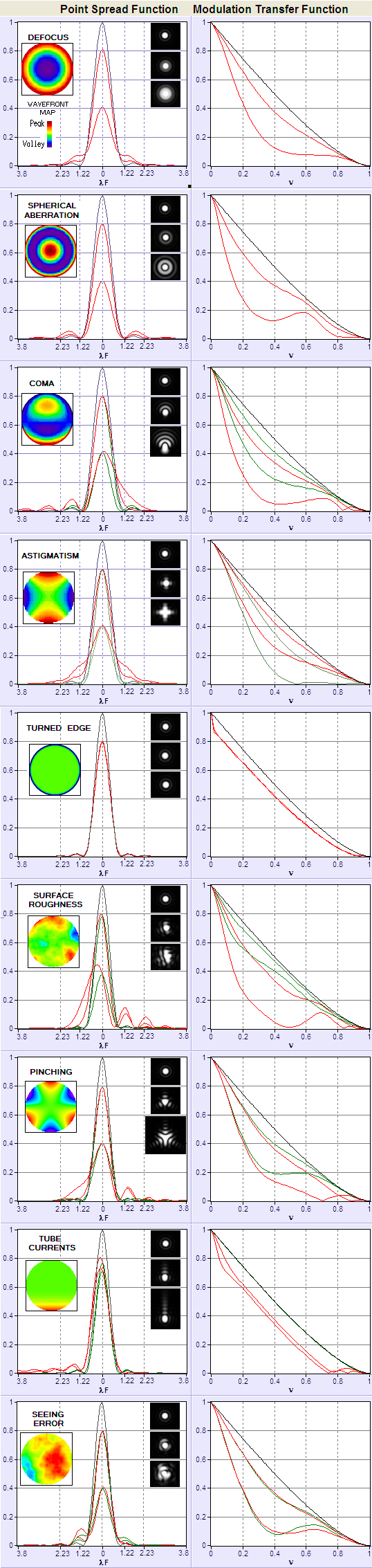
One example is the resolution threshold for low-contrast MTF-like planetary details which is, according to the LCB threshold level in FIG. 100, approximately half of that for brightly illuminated contrasty object. Another is a dark line on light background, which can be detected at an angular width several times smaller than the angular diffraction resolution limit for point-images of ~λ/D radians, because it is the Edge Spread Function, not the PSF, that is applicable in determining its diffraction intensity distribution. An actual object that comes very close to the standardized MTF scenario is a pair of nearly equally bright stars at the optimum brightness level. Resolution-wise, the MTF limiting resolution (cutoff frequency) is nearly identical to the empirical Dawes' limit in double star observing. However, for pairs farther from the optimum brightness level, or, especially, pairs with significant difference in brightness, the resolution limit is lower, or much lower. Still, despite the MTF being standardized to a single object form sample and brightness level, it is considered to be a reliable general indicator of the effect of wavefront aberrations - or any other factor affecting wave interference in the focal zone - on image quality. As mentioned, given relatively low RMS wavefront level of any aberration will result in near-identical overall contrast loss, but the specifics will vary somewhat. FIG. 101 illustrates variations in the aberrated PSF (left) and MTF (right) for common wavefront aberrations of 1/13.4 and 1/6.7 wave RMS (graphs generated by Aberrator freeware, Cor Berrevoets). FIGURE 101: PSF and MTF plots for clear aberration-free aperture (black), and aberrated (red) at the 0.80 Strehl level, and that wavefront error doubled. DEFOCUS: 1/4 and 1/2 wave P-V. Doubling the error halves the peak PSF intensity (Strehl), but the average contrast loss is three times greater (20% vs. 60%, given as a ratio number by the differential between the Strehl and 1). Note that the Strehl for 1/4 wave WFE of defocus is slightly higher than 0.80. PRIMARY SPHERICAL ABERRATION: 1/4 wave and 1/2 wave P-V errors have nearly identical effect on the PSF maximum as with defocus, but the more widely spread energy causes more of contrast loss at the lower frequencies, while the smaller central maxima results in somewhat better transfer at mid-to-high frequencies. The transfer is again inferior near the cutoff due to the smaller bright core with defocus. Being close to zero, the cutoff frequency for 1/2 wave P-V is about 20% lower in field conditions. PRIMARY COMA: 0.42 and 0.84 wave P-V have similar effect on the PSF peak value as 1/4 and 1/2 wave P-V of defocus or primary spherical. However, the actual contrast transfer varies significantly with the orientation of the asymmetrical aberrated pattern relative to MTF bars. It is the worst when the blur length is perpendicular to the bars (red), and the best when blur length has the same orientation (green). MTF plots hitting zero contrast near the cutoff and bouncing after, indicate contrast reversal. PRIMARY ASTIGMATISM: The effect of 0.37 and 0.74 wave P-V is similar to 1/4 and 1/2 wave of defocus in that the energy spread out of the Airy disc is mostly contained closer to central maxima, resulting in less of contrast loss at low frequencies. Unlike defocus, does not change radial symmetry of PSF, astigmatism gives to it cross-like shape which, similarly to coma's asymmetry, gives the best contrast transfer when cross orientation is identical to that of the bars (green) and the worst when it is at 45° angle. TURNED EDGE: 2.5 waves P-V is needed that turned edge starting at 95% the radius to lower the Strehl to 0.80. Lost energy is evenly spread wide out (the abrupt initial contrast loss ending at about 1/40 frequency indicates the radius of this spread as 40 times the cutoff frequency, or 40λF - over 30 times the Airy disc radius). Odd but expected TE property - due to the relatively small affected area (the RMS for 0.80 Strehl is whooping 0.28 wave) - is that increasing the aberration does almost no additional damage. ROUGHNESS: ~1/14 and ~1/7 wave RMS of roughness producing asymmetric PSF pattern, thus having contrast transfer vary with its orientation relative to MTF bars. Due to the random nature of the aberration, the P-V wavefront error can vary significantly for any given RMS/Strehl level. IHere, the P-V error ranges from -0.169 (blue speck on the wavefront map) to 0.374, and -345 to 0.745, respectively. RMS error also may not be as reliably related to the Strehl as with most other aberrations. PINCHING: 0.37 and 0.74 wave P-V of wavefront deformation caused by edge pinching at a three 120° separated points has the typical 3-sided symmetry (trefoil). the aberration is radially asymmetric, causing the contrast transfer to vary between the maximum (red, for zero, 120° and 240° orientation angle) and minimum (60°, 180° and 300° orientation). Other forms do occur, with or without some form of symmetry. About 30% of the frequency range toward high end shows contrast reversal. TUBE CURRENTS: 3/4 and 1.5 wave P-V wavefront error caused by tube currents affecting end 30% of the wavefront radius. Energy spreads mainly in the direction of wavefront deformation. Similarly to the TE, the RMS error (0.106 and 0.212, respectively) is disproportionally large vs. Strehl, and doubling the error has relatively small effect. Contrast transfer is the worst when the energy spreads orthogonally to MTF bars; for the aberrated energy spread having the same orientation as MTF bars is perfect (green). SEEING ERROR: Averaged PSF/MTF effect of ~1/14 and ~1/7 wave RMS of atmospheric turbulence. The P-V error can vary substantially (here is 0.43 and 0.86 wave, respectively). Seeing error fluctuates constantly around the average, as do the corresponding image contrast and resolution. Larger seeing errors (1/7 wave RMS is rather common with medium size apertures) reduces contrast level to that similar to twice smaller aperture for low-to-mid frequencies, with some high-frequency transfer (iincluding limiting resolution) advantage remaining. MTF contrast transfer generalized to the RMS wavefront error alone, regardless of the type of aberration is, as shown by Bob Shannon, given by a product of aberration-free MTF and the Aberration Transfer Function [ATF=1-(ω/0.18)2(1-4(ν-0.5)2), where ω is the RMS wavefront error in units of wavelength, and v is the normalized spatial frequency; not to confuse with the Amplitude Transfer Function - this is the only place where the Aberration Transfer Function is mentioned] for any given level of the RMS error, and aberration-free MTF, as illustrated at left for selected levels of RMS wavefront error (ω). It clearly shows that contrast transfer does not drop linearly, but exponentially with the increase in the RMS error. While the contrast loss is still negligible for ω=0.037 (1/8 wave P-V of primary spherical level), it is several times larger at the error doubled. Another 50% higher error, to 0.10 wave RMS, nearly doubles the loss, but yet another 50% increase, to 0.149, more than doubles the entire contrast loss at ω=0.10. Also, with the increase in error magnitude, maximum contrast drop gradually shifts from the lower mid frequencies to the mid frequencies. With small-to-moderate RMS wavefront errors, this generalized MTF can be assumed to also represent the averaged contrast drop for a given RMS error for asymmetrical aberrations, like coma and astigmatism, or for irregular wavefront deformations characteristic of the actual systems (due to their asymmetric form, such aberrations have contrast transfer varying with the MTF orientation). However, since the differences in contrast transfer over MTF frequency sub ranges for different aberration forms generally increase with the wavefront error - especially as it exceeds 0.15 wave RMS - the usefulness of this generalized MTF approach diminishes going beyond that level. ◄ 6.5. Strehl ratio ▐ 6.6.1. MTF - aberration compounding, CCD, limitations ► Home | Comments
Mtf functionformula
The MTF is a part of the complex function describing this process, called Optical transfer function (OTF). While OTF is limited to the effect of system PSF on imaging this single form of object - a sinusoidal intensity distribution - it is accepted as a performance indicator for imaging in general.
Modulation transfer function (MTF) is commonly used to describe the convolution of point spread functions (PSF) and the Gaussian (geometric) image of an object that is a continuous sinusoidal intensity pattern, in effect a continuum of dark and bright lines gradually changing from the maxima (in the middle of the bright line) to minima (middle of the dark line). The convolution integral sums up energy arising from the PSF blotches created at every point of the Gaussian image, and so describes the corresponding diffraction image of the pattern. Changes in the PSF due to aberrations, pupil obstructions and other factors affect the quality of this diffraction image, specifically its contrast level and phase distribution. In general, convolution with the PSF smoothes out, i.e. flattens intensity distribution of the sinusoidal (or any other) pattern, lowering the contrast and acting as a low-pass filter (i.e. imposing limit to resolution) - the larger PSF vs. pattern's frequency, the more so.
with the two factors at right being the real and imaginary part of the OTF, respectively (noting that the PSF is usually annotated as angle). Either can be plotted separately, the former, being cosine function, originating at 1 for zero spatial frequency, and the latter originating at zero. If PSF retains any form of symmetry around a line splitting it in two halves (i.e. symmetry in its pupil aberration function), the imaginary part vanishes (because in such case the shift can only be zero or π, for contrast reversal), and OTF reduces to OTF= MTFcos(PTF). This is the case with defocus, spherical aberration and astigmatism, for any orientation of the PSF, and with coma only for a single orientation, along the axis of aberration. For all other orientations the coma OTF consists of both, real and imaginary part. It is important to note that, since eiPTF=cos(PTF)+isin(PTF) does not represent a sum, rather coordinates of a complex number, the real part of the OTF does not represent the magnitude of OTF (i.e. MTF), except when PTF equals zero (no phase shift). If we use the common notation for the real and imaginary part, Re and Im, respectively, then the relation between them and the MTF is given by |OTF|= MTF= (Re2+Im2)0.5. As illustrated below, eiPTF is not a value, rather phase descriptor. Hence OTF magnitude is not affected by it. FIGURE 100: The magnitude and phase aspect of the OTF. The former expresses the effect on intensity modulation i.e. contrast (top), the latter on the spatial distribution (bottom). OTF magnitude depends solely on the relative magnitude of the minimum intensity of the sinusoidal pattern (IMIN) vs. its maximum (IMAX). In order to incorporate the effect of a possible phase shift, OTF is constructed within a unit circle in complex coordinates, with its real and imaginary parts reflecting the magnitude of phase shift, but not the OTF magnitude itself, which is in these coordinates given by a square root of the sum of squared real and imaginary parts of OTF, therefore remaining unit value independent of the phase shift (bottom right). OTF can also be defined in terms of PSF, as OTF
PRIMARY SPHERICAL ABERRATION: 1/4 wave and 1/2 wave P-V errors have nearly identical effect on the PSF maximum as with defocus, but the more widely spread energy causes more of contrast loss at the lower frequencies, while the smaller central maxima results in somewhat better transfer at mid-to-high frequencies. The transfer is again inferior near the cutoff due to the smaller bright core with defocus. Being close to zero, the cutoff frequency for 1/2 wave P-V is about 20% lower in field conditions. PRIMARY COMA: 0.42 and 0.84 wave P-V have similar effect on the PSF peak value as 1/4 and 1/2 wave P-V of defocus or primary spherical. However, the actual contrast transfer varies significantly with the orientation of the asymmetrical aberrated pattern relative to MTF bars. It is the worst when the blur length is perpendicular to the bars (red), and the best when blur length has the same orientation (green). MTF plots hitting zero contrast near the cutoff and bouncing after, indicate contrast reversal. PRIMARY ASTIGMATISM: The effect of 0.37 and 0.74 wave P-V is similar to 1/4 and 1/2 wave of defocus in that the energy spread out of the Airy disc is mostly contained closer to central maxima, resulting in less of contrast loss at low frequencies. Unlike defocus, does not change radial symmetry of PSF, astigmatism gives to it cross-like shape which, similarly to coma's asymmetry, gives the best contrast transfer when cross orientation is identical to that of the bars (green) and the worst when it is at 45° angle. TURNED EDGE: 2.5 waves P-V is needed that turned edge starting at 95% the radius to lower the Strehl to 0.80. Lost energy is evenly spread wide out (the abrupt initial contrast loss ending at about 1/40 frequency indicates the radius of this spread as 40 times the cutoff frequency, or 40λF - over 30 times the Airy disc radius). Odd but expected TE property - due to the relatively small affected area (the RMS for 0.80 Strehl is whooping 0.28 wave) - is that increasing the aberration does almost no additional damage. ROUGHNESS: ~1/14 and ~1/7 wave RMS of roughness producing asymmetric PSF pattern, thus having contrast transfer vary with its orientation relative to MTF bars. Due to the random nature of the aberration, the P-V wavefront error can vary significantly for any given RMS/Strehl level. IHere, the P-V error ranges from -0.169 (blue speck on the wavefront map) to 0.374, and -345 to 0.745, respectively. RMS error also may not be as reliably related to the Strehl as with most other aberrations. PINCHING: 0.37 and 0.74 wave P-V of wavefront deformation caused by edge pinching at a three 120° separated points has the typical 3-sided symmetry (trefoil). the aberration is radially asymmetric, causing the contrast transfer to vary between the maximum (red, for zero, 120° and 240° orientation angle) and minimum (60°, 180° and 300° orientation). Other forms do occur, with or without some form of symmetry. About 30% of the frequency range toward high end shows contrast reversal. TUBE CURRENTS: 3/4 and 1.5 wave P-V wavefront error caused by tube currents affecting end 30% of the wavefront radius. Energy spreads mainly in the direction of wavefront deformation. Similarly to the TE, the RMS error (0.106 and 0.212, respectively) is disproportionally large vs. Strehl, and doubling the error has relatively small effect. Contrast transfer is the worst when the energy spreads orthogonally to MTF bars; for the aberrated energy spread having the same orientation as MTF bars is perfect (green). SEEING ERROR: Averaged PSF/MTF effect of ~1/14 and ~1/7 wave RMS of atmospheric turbulence. The P-V error can vary substantially (here is 0.43 and 0.86 wave, respectively). Seeing error fluctuates constantly around the average, as do the corresponding image contrast and resolution. Larger seeing errors (1/7 wave RMS is rather common with medium size apertures) reduces contrast level to that similar to twice smaller aperture for low-to-mid frequencies, with some high-frequency transfer (iincluding limiting resolution) advantage remaining. MTF contrast transfer generalized to the RMS wavefront error alone, regardless of the type of aberration is, as shown by Bob Shannon, given by a product of aberration-free MTF and the Aberration Transfer Function [ATF=1-(ω/0.18)2(1-4(ν-0.5)2), where ω is the RMS wavefront error in units of wavelength, and v is the normalized spatial frequency; not to confuse with the Amplitude Transfer Function - this is the only place where the Aberration Transfer Function is mentioned] for any given level of the RMS error, and aberration-free MTF, as illustrated at left for selected levels of RMS wavefront error (ω). It clearly shows that contrast transfer does not drop linearly, but exponentially with the increase in the RMS error. While the contrast loss is still negligible for ω=0.037 (1/8 wave P-V of primary spherical level), it is several times larger at the error doubled. Another 50% higher error, to 0.10 wave RMS, nearly doubles the loss, but yet another 50% increase, to 0.149, more than doubles the entire contrast loss at ω=0.10. Also, with the increase in error magnitude, maximum contrast drop gradually shifts from the lower mid frequencies to the mid frequencies. With small-to-moderate RMS wavefront errors, this generalized MTF can be assumed to also represent the averaged contrast drop for a given RMS error for asymmetrical aberrations, like coma and astigmatism, or for irregular wavefront deformations characteristic of the actual systems (due to their asymmetric form, such aberrations have contrast transfer varying with the MTF orientation). However, since the differences in contrast transfer over MTF frequency sub ranges for different aberration forms generally increase with the wavefront error - especially as it exceeds 0.15 wave RMS - the usefulness of this generalized MTF approach diminishes going beyond that level.
The more highly corrected fluorite and plan-fluorite objectives have better color correction (at least three wavelengths) and feature flat fields (plan versions) in viewfields up to 26 millimeters in diameter. Due to the use of more advanced specialized glasses, fluorites are able to transmit ultraviolet wavelengths with high efficiency. Fluorite objectives are available for all contrast-enhancing modes, and special high-quality versions are available for polarized light and DIC. The apochromat objectives are the best performers and so are produced at the highest numerical aperture with color correction for at least four wavelengths. Plan versions reduce transmission efficiency, but produce spectacular images with a high degree of field flatness over the entire viewfield. As the need for specialized objectives grows with advances in technology, new apochromats are being designed to push the envelope with regards to color correction (360 to 700 nanometers or more), numerical aperture (up to 1.49), working distance, and suitability for various immersion media.
Modulation transferfunctionin Ophthalmology
FIGURE 100: The magnitude and phase aspect of the OTF. The former expresses the effect on intensity modulation i.e. contrast (top), the latter on the spatial distribution (bottom). OTF magnitude depends solely on the relative magnitude of the minimum intensity of the sinusoidal pattern (IMIN) vs. its maximum (IMAX). In order to incorporate the effect of a possible phase shift, OTF is constructed within a unit circle in complex coordinates, with its real and imaginary parts reflecting the magnitude of phase shift, but not the OTF magnitude itself, which is in these coordinates given by a square root of the sum of squared real and imaginary parts of OTF, therefore remaining unit value independent of the phase shift (bottom right).
Erin E. Wilson and Michael W. Davidson - National High Magnetic Field Laboratory, 1800 East Paul Dirac Dr., The Florida State University, Tallahassee, Florida, 32310.
Mtf functionin optical
At right, shown is the effect of 1 wave P-V of defocus on the image of an object that is not the standard MTF pattern, but one in which bar width is oriented horizontally, with the line width changing continuously according to the spatial frequency. Top image (A) is aberration-free, and bottom (B) defocused one. If the aberration is large enough - in the case of defocus ~0.9 wave P-V or larger - image of such object will show contrast reversal - where bright lines become dark and vice versa - indicated by the OTF, but not the MTF. The reason was immediately apparent from the PSF intensity distribution for 1 wave of defocus, developing dark circle (minima) at the center of the pattern. Hence, MTF does provide information on contrast transfer, but not on the image itself. To reconstruct the image, we need OTF. This, however. may have significance only with large aberrations, generally about 1 wave P-V and larger (a few more examples at ). OTF for smaller aberrations does not fall below zero, thus there is no contrast reversal to affect image. As plot at right show, the standard MTF output by OSLO (dashed) does not equal the absolute value of OTF, indicating that MTF plot may vary somewhat depending on the algorithm applied. If defined as the absolute value of OTF magnitude, MTF should continue through the red plot section. INSET C: In addition to phase shift, if PSF intensity is varying radially it will also cause different contrast transfer for different orientations of the PSF relative to MTF pattern. A complete MTF integral has radial component, thus it integrates for all orientations of the PSF relative to the line pattern. Graphically, it is represented by a volume figure, formed by continuous change of the integration angle (i.e. pattern orientation) through a full circle, or 2π radians (right). This volume may be looked at as a total contrast, transfer. For radially symmetrical aberrations, like spherical or defocus, there is no variation in contrast transfer with orientation, and it is fully represented by any single orientation, i.e. 2-D MTF. For radially asymmetrical aberrations, like coma or astigmatism, the transfer, hence also the MTF volume cross section profile, changes with the orientation, forming rotationally asymmetrical 3-D figure. The default representation is often to show MTF for sagittal (perpendicular to MTF bar orientation) and tangential (along bar orientation) PSF orientation. This works well with coma, where it assesses the two limiting effects, the minimum (the latter) and maximum (former), giving a good idea of the average effect on contrast transfer. With astigmatism, however, which at the minimum variance focus causes a cross-like PSF deformation, with 0 (π) and π/2 (3π/2) PSF rotation producing the same effect, while the maximum effect on MTF contrast transfer is for π/4 (+π) PSF rotations. Contrast transfer for all PSF orientations also can be azimuthally averaged, giving mean contrast transfer for the aberration. INSET D: Note that the graph on top represents monochromatic MTF (as indicated by the cutoff frequency 1/λF). Polychromatic MTF cutoff frequency - and to a slight extent, the overall shape - is determined by the combined PSF intensity distribution within the wavelength range. As large inset at right illustrates, while PSF for individual wavelengths differ significantly at the ends of given spectral range (first minima being at 1.22λF), when combined they nearly offset around the central wavelength's PSF. Actual PSFs for different wavelengths also normally differ in their intensity, both emitted by object and perceived by eye, which may affect contrast transfer by giving to it bias toward the wavelength of maximum intensity, since the intensity distribution loses the symmetry around central wavelength). There is little difference between centered monochromatic (green) and full-range polychromatic PSF (black), thus also MTF, regardless of the sensitivity mode. The PSF differ mainly in the ring area (photopic vs. even spectrum, small inset), and with MTF it is limited to the value of cutoff frequency, which is for polychromatic light determined by that for the shortest wavelength. This is based on the formalism describing polychromatic contrast transfer as the average sum of the transfer c for given frequency ν at each of i wavelengths, MTF(ν)=Σc(ν)i/i. As a result, long and short wavelengths nearly offset each other for the most of frequency range, with the resulting polychromatic MTF for the range gravitating toward that of the mid-wavelength; some residual contrast transfer extends beyond that for the central wavelength, not significantly influenced by eye sensitivity factor. While the nominal cutoff frequency for polychromatic MTF equals that of the shortest wavelength, it actual contrast transfer is much closer to that of the central wavelength.
Simple eyepieces such as the Huygenian and Ramsden and their achromatized counterparts will not correct for residual chromatic difference of magnification in the intermediate image, especially when used in combination with high magnification achromatic objectives as well as any fluorite or apochromatic objectives. To remedy this, manufacturers produce compensating eyepieces that introduce an equal, but opposite, chromatic error in the lens elements. Compensating eyepieces may be either of the positive or negative type, and must be used at all magnifications with fluorite, apochromatic and all variations of plan objectives (they can also be used to advantage with achromatic objectives of 40x and higher). In recent years, modern microscope objectives have their correction for chromatic difference of magnification either built into the objectives themselves or corrected in the tube lens.
INSET A: TOP LEFT: Standardized MTF object form is a continuum of parallel, equally spaced bright contrasty lines on dark background, with irradiance modulation defined as infinite sinusoidal distribution. The line width, equaling that of the dark/light pair, is inversely proportional to the spatial frequency ν, normalized to 1 at the cutoff frequency D/λ cycles per radian (the inverse of the angular limit to resolution λ/D in radians, D being the aperture diameter), where image contrast drops to zero (linear cutoff frequency is the inverse of the linear limit to resolution λF, or 1/λF in lines per mm, for λ in mm). This form of intensity distribution can be represented as periodic sinusoidal wave, with the contrast determined by the relative intensity of its maxima vs. minima. Image of this pattern has the relative intensity and contrast dampened due to the effect of diffraction, whether without or with aberrations present, At any given frequency, MTF is a ratio of the output (image) to input (object) modulation amplitude. Mathematically, it is Fourier transform of the system's PSF (more specifically, it is an integrated sum of the PSFs for every point over its intensity distribution profile, i.e. convolution of object's Gaussian image and aperture's PSF). At the limit of resolution for aberration-free aperture, the line width is nearly equal to the aperture's FWHM. TOP RIGHT: The modulation transfer function - MTF - for clear aberration-free aperture (P) is the ultimate limit to the overall contrast and resolution set by diffraction for this type of object. Normalized to 1, it equals the relative overlapping area of two circles of unit diameter (graphic representation of pupil autocorrelation), at a center separation ν, the normalized spatial frequency (top right, yellow overlap area for ν~0.3). MTF in aberrated aperture (A, 1/4 wave P-V of spherical aberration) is lower than P over the entire range of frequencies. The standard MTF plot is non-linear, in that any given linear change of contrast is proportional to the normalized frequency (i.e. same linear change at, say, 0.5 frequency is about twice the relative change at 0.25 frequency). The relative contrast (RC) shows contrast differential between the two more clearly, directly comparable, in units of the perfect aperture contrast level normalized to 1 over the frequency range. The low-contrast thresholds for bright (LCB) and dim (LCD) details, is an informal, but useful addition by Rutten and Venrooij. It indicates that the approximate cutoff levels for typical low-contrast details - about 10% inherent contrast - requires higher minimum contrast at the resolution limit than the standard bright, contrasty MTF pattern. As a consequence, their cutoff frequencies are lower than for high-contrast details. The original plots are constructed with respect to a perfect aperture transfer line starting at 0.1 contrast for zero frequency, decreasing toward zero at the regular cutoff frequency, with the limit to resolution determined by the minimum contrast required by the eye, approximated at 5% for the bright and 2-3 times as much for dim details, both steadily increasing from low toward high frequencies; the LCB and LCD lines above are based on these plots, only with the contrast at zero frequency normalized to 1, i.e stretched out tenfold vertically. The two lower threshold lines are for bright and dim details with 100% inherent contrast. As shown, the approximate resolution limit is 1/2 and 1/7 of the standard MTF cutoff frequency for bright and dim low-contrast objects, respectively. For contrasty dim details (HCD, High-Contrast-Dim), the approximate minimum contrast level HCD indicates the limiting resolution of about 0.7 frequency. It is somewhat better for contrasty bright detail (HCB) - near 0.9 frequency - but the resolution limit would require the maximum contrast. Again, these are only general approximations, and may be inaccurate, particularly toward cutoff frequency, since the actual minimum contrast required by eye increases exponentially close to the limit of resolution (FIG. 236C). Note that different patterns of intensity distribution have different contrast transfer; for instance, periodic square wave (i.e. pattern of sharply defined dark and bright lines) will have contrast transfer higher at all frequencies either in aberration-free aperture (solid blue line), or for any given level of aberration, as the CTF for clear aberration-free aperture (blue plot) indicates. However, the relative change in contrast transfer due to aberrations and/or obstructions are generally similar for MTF and CTF. INSET B: As mentioned, the complete OTF describes both, contrast transfer, or modultion (MTF), and phase transfer from object to its image. Phase transfer can only occur if diffraction peak is displaced away from the intersection of chief ray (one that passes through the center of the aperture stop) and image plane. That causes lateral shift of the MTF bar pattern, as illustrated below for coma (left) and defocus (right). Of all conic aberration forms, only coma induces phase shift due to its asymmetric PSF, except when its axis of aberration ( i.e. axis of symmetry for the geometric blur) is parallel with MTF bars. Other conic aberrations can also induce phase shift, but as a consequence of the change in PSF intensity distribution. Shown are only coma PSFs for a few selected points on the object (MTF pattern subjected to imaging) are shown, but the actual calculation includes PSFs from all points of the object-pattern. The combined amplitude they produce at every point in the image plane determines the intensity pattern of the image-pattern, i.e. its contrast transfer characteristics (note that PSFs shown are independent, not a convolution of the Gaussian image, thus the image pattern is only an illustration). The PSF peak shift for λ/2 wave P-V of primary coma (0.088 wave RMS) is λF, which is on this illustration about 1/7.5 of the full phase of the sinusoidal pattern (indicating the corresponding pattern frequency as 7.5 times the λF cutoff frequency, or ~0.13 , resulting in 2π/7.5 phase shift of the MTF pattern. Phase shift does not affect contrast transfer, which is determined by the combined wave amplitude itself, which is MTF domain. Since the PSF shift, when present, has constant value, the corresponding phase shift varies across the range of frequencies, and can be plotted as a separate PTF. At right, shown is the effect of 1 wave P-V of defocus on the image of an object that is not the standard MTF pattern, but one in which bar width is oriented horizontally, with the line width changing continuously according to the spatial frequency. Top image (A) is aberration-free, and bottom (B) defocused one. If the aberration is large enough - in the case of defocus ~0.9 wave P-V or larger - image of such object will show contrast reversal - where bright lines become dark and vice versa - indicated by the OTF, but not the MTF. The reason was immediately apparent from the PSF intensity distribution for 1 wave of defocus, developing dark circle (minima) at the center of the pattern. Hence, MTF does provide information on contrast transfer, but not on the image itself. To reconstruct the image, we need OTF. This, however. may have significance only with large aberrations, generally about 1 wave P-V and larger (a few more examples at ). OTF for smaller aberrations does not fall below zero, thus there is no contrast reversal to affect image. As plot at right show, the standard MTF output by OSLO (dashed) does not equal the absolute value of OTF, indicating that MTF plot may vary somewhat depending on the algorithm applied. If defined as the absolute value of OTF magnitude, MTF should continue through the red plot section. INSET C: In addition to phase shift, if PSF intensity is varying radially it will also cause different contrast transfer for different orientations of the PSF relative to MTF pattern. A complete MTF integral has radial component, thus it integrates for all orientations of the PSF relative to the line pattern. Graphically, it is represented by a volume figure, formed by continuous change of the integration angle (i.e. pattern orientation) through a full circle, or 2π radians (right). This volume may be looked at as a total contrast, transfer. For radially symmetrical aberrations, like spherical or defocus, there is no variation in contrast transfer with orientation, and it is fully represented by any single orientation, i.e. 2-D MTF. For radially asymmetrical aberrations, like coma or astigmatism, the transfer, hence also the MTF volume cross section profile, changes with the orientation, forming rotationally asymmetrical 3-D figure. The default representation is often to show MTF for sagittal (perpendicular to MTF bar orientation) and tangential (along bar orientation) PSF orientation. This works well with coma, where it assesses the two limiting effects, the minimum (the latter) and maximum (former), giving a good idea of the average effect on contrast transfer. With astigmatism, however, which at the minimum variance focus causes a cross-like PSF deformation, with 0 (π) and π/2 (3π/2) PSF rotation producing the same effect, while the maximum effect on MTF contrast transfer is for π/4 (+π) PSF rotations. Contrast transfer for all PSF orientations also can be azimuthally averaged, giving mean contrast transfer for the aberration. INSET D: Note that the graph on top represents monochromatic MTF (as indicated by the cutoff frequency 1/λF). Polychromatic MTF cutoff frequency - and to a slight extent, the overall shape - is determined by the combined PSF intensity distribution within the wavelength range. As large inset at right illustrates, while PSF for individual wavelengths differ significantly at the ends of given spectral range (first minima being at 1.22λF), when combined they nearly offset around the central wavelength's PSF. Actual PSFs for different wavelengths also normally differ in their intensity, both emitted by object and perceived by eye, which may affect contrast transfer by giving to it bias toward the wavelength of maximum intensity, since the intensity distribution loses the symmetry around central wavelength). There is little difference between centered monochromatic (green) and full-range polychromatic PSF (black), thus also MTF, regardless of the sensitivity mode. The PSF differ mainly in the ring area (photopic vs. even spectrum, small inset), and with MTF it is limited to the value of cutoff frequency, which is for polychromatic light determined by that for the shortest wavelength. This is based on the formalism describing polychromatic contrast transfer as the average sum of the transfer c for given frequency ν at each of i wavelengths, MTF(ν)=Σc(ν)i/i. As a result, long and short wavelengths nearly offset each other for the most of frequency range, with the resulting polychromatic MTF for the range gravitating toward that of the mid-wavelength; some residual contrast transfer extends beyond that for the central wavelength, not significantly influenced by eye sensitivity factor. While the nominal cutoff frequency for polychromatic MTF equals that of the shortest wavelength, it actual contrast transfer is much closer to that of the central wavelength.
ROUGHNESS: ~1/14 and ~1/7 wave RMS of roughness producing asymmetric PSF pattern, thus having contrast transfer vary with its orientation relative to MTF bars. Due to the random nature of the aberration, the P-V wavefront error can vary significantly for any given RMS/Strehl level. IHere, the P-V error ranges from -0.169 (blue speck on the wavefront map) to 0.374, and -345 to 0.745, respectively. RMS error also may not be as reliably related to the Strehl as with most other aberrations. PINCHING: 0.37 and 0.74 wave P-V of wavefront deformation caused by edge pinching at a three 120° separated points has the typical 3-sided symmetry (trefoil). the aberration is radially asymmetric, causing the contrast transfer to vary between the maximum (red, for zero, 120° and 240° orientation angle) and minimum (60°, 180° and 300° orientation). Other forms do occur, with or without some form of symmetry. About 30% of the frequency range toward high end shows contrast reversal. TUBE CURRENTS: 3/4 and 1.5 wave P-V wavefront error caused by tube currents affecting end 30% of the wavefront radius. Energy spreads mainly in the direction of wavefront deformation. Similarly to the TE, the RMS error (0.106 and 0.212, respectively) is disproportionally large vs. Strehl, and doubling the error has relatively small effect. Contrast transfer is the worst when the energy spreads orthogonally to MTF bars; for the aberrated energy spread having the same orientation as MTF bars is perfect (green). SEEING ERROR: Averaged PSF/MTF effect of ~1/14 and ~1/7 wave RMS of atmospheric turbulence. The P-V error can vary substantially (here is 0.43 and 0.86 wave, respectively). Seeing error fluctuates constantly around the average, as do the corresponding image contrast and resolution. Larger seeing errors (1/7 wave RMS is rather common with medium size apertures) reduces contrast level to that similar to twice smaller aperture for low-to-mid frequencies, with some high-frequency transfer (iincluding limiting resolution) advantage remaining. MTF contrast transfer generalized to the RMS wavefront error alone, regardless of the type of aberration is, as shown by Bob Shannon, given by a product of aberration-free MTF and the Aberration Transfer Function [ATF=1-(ω/0.18)2(1-4(ν-0.5)2), where ω is the RMS wavefront error in units of wavelength, and v is the normalized spatial frequency; not to confuse with the Amplitude Transfer Function - this is the only place where the Aberration Transfer Function is mentioned] for any given level of the RMS error, and aberration-free MTF, as illustrated at left for selected levels of RMS wavefront error (ω). It clearly shows that contrast transfer does not drop linearly, but exponentially with the increase in the RMS error. While the contrast loss is still negligible for ω=0.037 (1/8 wave P-V of primary spherical level), it is several times larger at the error doubled. Another 50% higher error, to 0.10 wave RMS, nearly doubles the loss, but yet another 50% increase, to 0.149, more than doubles the entire contrast loss at ω=0.10. Also, with the increase in error magnitude, maximum contrast drop gradually shifts from the lower mid frequencies to the mid frequencies. With small-to-moderate RMS wavefront errors, this generalized MTF can be assumed to also represent the averaged contrast drop for a given RMS error for asymmetrical aberrations, like coma and astigmatism, or for irregular wavefront deformations characteristic of the actual systems (due to their asymmetric form, such aberrations have contrast transfer varying with the MTF orientation). However, since the differences in contrast transfer over MTF frequency sub ranges for different aberration forms generally increase with the wavefront error - especially as it exceeds 0.15 wave RMS - the usefulness of this generalized MTF approach diminishes going beyond that level.
Modern microscopes feature vastly improved plan-corrected objectives in which the primary image has much less curvature of field than older objectives. In addition, most microscopes now feature much wider body tubes that have greatly increased the size of intermediate images. To address these new features, manufacturers now produce wide-eyefield eyepieces that increase the viewable area of the specimen by as much as 40 percent. Because the strategies of eyepiece-objective correction techniques vary from manufacturer to manufacturer, it is very important to use only eyepieces recommended by a specific manufacturer for use with their objectives. Additionally, most eyepieces on research-level microscopes have a focusing ring, which makes it possible to precisely focus on reticles that are mounted into the space where the intermediate image resides. The focusing ring also makes it possible to establish a condition on the microscope that is referred to as being parfocal, where operators with different eyesights can configure the microscope in such a manner that the images produced by the objective remain in focus when a new objective is inserted into the optical path.
OTF = MTF[cos(PTF) + isin(PTF)] = MTFcos(PTF) + MTFisin(PTF), with the two factors at right being the real and imaginary part of the OTF, respectively (noting that the PSF is usually annotated as angle). Either can be plotted separately, the former, being cosine function, originating at 1 for zero spatial frequency, and the latter originating at zero. If PSF retains any form of symmetry around a line splitting it in two halves (i.e. symmetry in its pupil aberration function), the imaginary part vanishes (because in such case the shift can only be zero or π, for contrast reversal), and OTF reduces to OTF= MTFcos(PTF). This is the case with defocus, spherical aberration and astigmatism, for any orientation of the PSF, and with coma only for a single orientation, along the axis of aberration. For all other orientations the coma OTF consists of both, real and imaginary part. It is important to note that, since eiPTF=cos(PTF)+isin(PTF) does not represent a sum, rather coordinates of a complex number, the real part of the OTF does not represent the magnitude of OTF (i.e. MTF), except when PTF equals zero (no phase shift). If we use the common notation for the real and imaginary part, Re and Im, respectively, then the relation between them and the MTF is given by |OTF|= MTF= (Re2+Im2)0.5. As illustrated below, eiPTF is not a value, rather phase descriptor. Hence OTF magnitude is not affected by it. FIGURE 100: The magnitude and phase aspect of the OTF. The former expresses the effect on intensity modulation i.e. contrast (top), the latter on the spatial distribution (bottom). OTF magnitude depends solely on the relative magnitude of the minimum intensity of the sinusoidal pattern (IMIN) vs. its maximum (IMAX). In order to incorporate the effect of a possible phase shift, OTF is constructed within a unit circle in complex coordinates, with its real and imaginary parts reflecting the magnitude of phase shift, but not the OTF magnitude itself, which is in these coordinates given by a square root of the sum of squared real and imaginary parts of OTF, therefore remaining unit value independent of the phase shift (bottom right). OTF can also be defined in terms of PSF, as OTF
FIGURE 101: PSF and MTF plots for clear aberration-free aperture (black), and aberrated (red) at the 0.80 Strehl level, and that wavefront error doubled. DEFOCUS: 1/4 and 1/2 wave P-V. Doubling the error halves the peak PSF intensity (Strehl), but the average contrast loss is three times greater (20% vs. 60%, given as a ratio number by the differential between the Strehl and 1). Note that the Strehl for 1/4 wave WFE of defocus is slightly higher than 0.80. PRIMARY SPHERICAL ABERRATION: 1/4 wave and 1/2 wave P-V errors have nearly identical effect on the PSF maximum as with defocus, but the more widely spread energy causes more of contrast loss at the lower frequencies, while the smaller central maxima results in somewhat better transfer at mid-to-high frequencies. The transfer is again inferior near the cutoff due to the smaller bright core with defocus. Being close to zero, the cutoff frequency for 1/2 wave P-V is about 20% lower in field conditions. PRIMARY COMA: 0.42 and 0.84 wave P-V have similar effect on the PSF peak value as 1/4 and 1/2 wave P-V of defocus or primary spherical. However, the actual contrast transfer varies significantly with the orientation of the asymmetrical aberrated pattern relative to MTF bars. It is the worst when the blur length is perpendicular to the bars (red), and the best when blur length has the same orientation (green). MTF plots hitting zero contrast near the cutoff and bouncing after, indicate contrast reversal. PRIMARY ASTIGMATISM: The effect of 0.37 and 0.74 wave P-V is similar to 1/4 and 1/2 wave of defocus in that the energy spread out of the Airy disc is mostly contained closer to central maxima, resulting in less of contrast loss at low frequencies. Unlike defocus, does not change radial symmetry of PSF, astigmatism gives to it cross-like shape which, similarly to coma's asymmetry, gives the best contrast transfer when cross orientation is identical to that of the bars (green) and the worst when it is at 45° angle. TURNED EDGE: 2.5 waves P-V is needed that turned edge starting at 95% the radius to lower the Strehl to 0.80. Lost energy is evenly spread wide out (the abrupt initial contrast loss ending at about 1/40 frequency indicates the radius of this spread as 40 times the cutoff frequency, or 40λF - over 30 times the Airy disc radius). Odd but expected TE property - due to the relatively small affected area (the RMS for 0.80 Strehl is whooping 0.28 wave) - is that increasing the aberration does almost no additional damage. ROUGHNESS: ~1/14 and ~1/7 wave RMS of roughness producing asymmetric PSF pattern, thus having contrast transfer vary with its orientation relative to MTF bars. Due to the random nature of the aberration, the P-V wavefront error can vary significantly for any given RMS/Strehl level. IHere, the P-V error ranges from -0.169 (blue speck on the wavefront map) to 0.374, and -345 to 0.745, respectively. RMS error also may not be as reliably related to the Strehl as with most other aberrations. PINCHING: 0.37 and 0.74 wave P-V of wavefront deformation caused by edge pinching at a three 120° separated points has the typical 3-sided symmetry (trefoil). the aberration is radially asymmetric, causing the contrast transfer to vary between the maximum (red, for zero, 120° and 240° orientation angle) and minimum (60°, 180° and 300° orientation). Other forms do occur, with or without some form of symmetry. About 30% of the frequency range toward high end shows contrast reversal. TUBE CURRENTS: 3/4 and 1.5 wave P-V wavefront error caused by tube currents affecting end 30% of the wavefront radius. Energy spreads mainly in the direction of wavefront deformation. Similarly to the TE, the RMS error (0.106 and 0.212, respectively) is disproportionally large vs. Strehl, and doubling the error has relatively small effect. Contrast transfer is the worst when the energy spreads orthogonally to MTF bars; for the aberrated energy spread having the same orientation as MTF bars is perfect (green). SEEING ERROR: Averaged PSF/MTF effect of ~1/14 and ~1/7 wave RMS of atmospheric turbulence. The P-V error can vary substantially (here is 0.43 and 0.86 wave, respectively). Seeing error fluctuates constantly around the average, as do the corresponding image contrast and resolution. Larger seeing errors (1/7 wave RMS is rather common with medium size apertures) reduces contrast level to that similar to twice smaller aperture for low-to-mid frequencies, with some high-frequency transfer (iincluding limiting resolution) advantage remaining. MTF contrast transfer generalized to the RMS wavefront error alone, regardless of the type of aberration is, as shown by Bob Shannon, given by a product of aberration-free MTF and the Aberration Transfer Function [ATF=1-(ω/0.18)2(1-4(ν-0.5)2), where ω is the RMS wavefront error in units of wavelength, and v is the normalized spatial frequency; not to confuse with the Amplitude Transfer Function - this is the only place where the Aberration Transfer Function is mentioned] for any given level of the RMS error, and aberration-free MTF, as illustrated at left for selected levels of RMS wavefront error (ω). It clearly shows that contrast transfer does not drop linearly, but exponentially with the increase in the RMS error. While the contrast loss is still negligible for ω=0.037 (1/8 wave P-V of primary spherical level), it is several times larger at the error doubled. Another 50% higher error, to 0.10 wave RMS, nearly doubles the loss, but yet another 50% increase, to 0.149, more than doubles the entire contrast loss at ω=0.10. Also, with the increase in error magnitude, maximum contrast drop gradually shifts from the lower mid frequencies to the mid frequencies. With small-to-moderate RMS wavefront errors, this generalized MTF can be assumed to also represent the averaged contrast drop for a given RMS error for asymmetrical aberrations, like coma and astigmatism, or for irregular wavefront deformations characteristic of the actual systems (due to their asymmetric form, such aberrations have contrast transfer varying with the MTF orientation). However, since the differences in contrast transfer over MTF frequency sub ranges for different aberration forms generally increase with the wavefront error - especially as it exceeds 0.15 wave RMS - the usefulness of this generalized MTF approach diminishes going beyond that level.
It is important to note that, since eiPTF=cos(PTF)+isin(PTF) does not represent a sum, rather coordinates of a complex number, the real part of the OTF does not represent the magnitude of OTF (i.e. MTF), except when PTF equals zero (no phase shift). If we use the common notation for the real and imaginary part, Re and Im, respectively, then the relation between them and the MTF is given by |OTF|= MTF= (Re2+Im2)0.5. As illustrated below, eiPTF is not a value, rather phase descriptor. Hence OTF magnitude is not affected by it. FIGURE 100: The magnitude and phase aspect of the OTF. The former expresses the effect on intensity modulation i.e. contrast (top), the latter on the spatial distribution (bottom). OTF magnitude depends solely on the relative magnitude of the minimum intensity of the sinusoidal pattern (IMIN) vs. its maximum (IMAX). In order to incorporate the effect of a possible phase shift, OTF is constructed within a unit circle in complex coordinates, with its real and imaginary parts reflecting the magnitude of phase shift, but not the OTF magnitude itself, which is in these coordinates given by a square root of the sum of squared real and imaginary parts of OTF, therefore remaining unit value independent of the phase shift (bottom right). OTF can also be defined in terms of PSF, as OTF
The OTF consists of two components: (1) MTF, and (2) phase-transfer function (PTF). The former is its modulus, or magnitude, expressing the relative change in contrast of the pattern image vs. aberration-free aperture, and the latter quantifies the linear lateral shift of this pattern caused by the change in PSF intensity distribution due to aberration. That intensity distribution change may be radially symmetric (such as draining of the energy from the central maxima with defocus or spherical aberration), or asymmetric, for example due to coma aberration (FIG. 100, middle). The basic relation between OTF, MTF and PTF can be presented as: OTF = |OTF|e iPTF = MTFe iPTF implying that the MTF is the absolute value of the OTF (e is the natural logarithm base, 2.718; note that the equality is not present with the commonly used form of the OTF, MTF, which entirely omits the phase factor). Since OTF contains the imaginary number i, it is a complex function consisting from the real and imaginary part, the latter being the part containing the imaginary number. The imaginary number i=(-1)0.5 is convenient for expressing angular shifts, in this case angular shift of the sinusoidal MTF intensity pattern phase at a given Gaussian image point due to the pattern's lateral shift, caused by aberrated PSF. With eiPTF=cos(PTF)+isin(PTF), the two parts of OTF function can be expressed as: OTF = MTF[cos(PTF) + isin(PTF)] = MTFcos(PTF) + MTFisin(PTF), with the two factors at right being the real and imaginary part of the OTF, respectively (noting that the PSF is usually annotated as angle). Either can be plotted separately, the former, being cosine function, originating at 1 for zero spatial frequency, and the latter originating at zero. If PSF retains any form of symmetry around a line splitting it in two halves (i.e. symmetry in its pupil aberration function), the imaginary part vanishes (because in such case the shift can only be zero or π, for contrast reversal), and OTF reduces to OTF= MTFcos(PTF). This is the case with defocus, spherical aberration and astigmatism, for any orientation of the PSF, and with coma only for a single orientation, along the axis of aberration. For all other orientations the coma OTF consists of both, real and imaginary part. It is important to note that, since eiPTF=cos(PTF)+isin(PTF) does not represent a sum, rather coordinates of a complex number, the real part of the OTF does not represent the magnitude of OTF (i.e. MTF), except when PTF equals zero (no phase shift). If we use the common notation for the real and imaginary part, Re and Im, respectively, then the relation between them and the MTF is given by |OTF|= MTF= (Re2+Im2)0.5. As illustrated below, eiPTF is not a value, rather phase descriptor. Hence OTF magnitude is not affected by it. FIGURE 100: The magnitude and phase aspect of the OTF. The former expresses the effect on intensity modulation i.e. contrast (top), the latter on the spatial distribution (bottom). OTF magnitude depends solely on the relative magnitude of the minimum intensity of the sinusoidal pattern (IMIN) vs. its maximum (IMAX). In order to incorporate the effect of a possible phase shift, OTF is constructed within a unit circle in complex coordinates, with its real and imaginary parts reflecting the magnitude of phase shift, but not the OTF magnitude itself, which is in these coordinates given by a square root of the sum of squared real and imaginary parts of OTF, therefore remaining unit value independent of the phase shift (bottom right). OTF can also be defined in terms of PSF, as OTF(ν)=∫PSF(x)e-iνx dx, where x is the spatial coordinate in the image plane. It implies that OTF is the Fourier transform of PSF. It is also evident from the fact that OTF can be obtained by self-convolution of the pupil function (same as autocorrelation for symmetrical functions) which - according to the convolution theorem stating that the Fourier transform of a convolution of two functions equals the product of their individual Fourier transforms - implies that the Fourier transform of OTF is the squared modulus of the coherent (point) spread function (which is the Fourier transform of aberration free pupil function), i.e. PSF. Or, more directly, just as the Fourier transform of aberration-free pupil function (i.e. Fourier transform of the square pulse) is sinc function, so is the Fourier transform of triangular function - which is the form of aberration-free 1-D OTF for square pupil, with the OTF form for circular pupil being only slightly different - the sinc function squared, or PSF. In other words, the PSF is proportional in form to the continuous spectrum of frequencies contained as a sum of harmonics in the triangular (or near-triangular) function form. It is important to note that the OTF relations above are, by their basic concept, valid only for incoherent light. Formal derivation states that this type of pattern in coherent light would be reproduced without any distortions in amplitude or phase, i.e. with 100% contrast transfer, with the sudden drop to zero at the cutoff frequency 2λ/D (coherent transfer function). As above relations show, MTF does not include possible lateral shift of intensity pattern in any way. This is not by choice, rather by the inherent property of MTF defined as the modulus (magnitude) of contrast transfer as a function of spatial frequency, with every spatial frequency treated as an isolated contributor to the function. Thus, lateral shift of the pattern is no factor, only the contrast level is recorded. MTF alone shows the efficiency of contrast transfer from the object to its image with zero intensity phase shift, for a single orientation in the aberrated image, normally that along the axis of aberration. However, 180° (π radians) phase shift, which can be caused by large amounts of aberrations, will result in contrast reversal, i.e. switch of bright and dark areas in the image vs. object. For instance, such image of F, in addition to it being distorted by the large level of aberration, could make it unrecognizable, even if contrast needed for detection is there. Hence, the OTF phase factor is potentially important factor in predicting image quality, but only in the presence of large aberrations, well above the level found near axis in optical telescopes (for instance, contrast reversal due to primary spherical occurs at near 2λ P-V wavefront error). Similar to MTF is the contrast transfer function (CTF), the difference being that the latter describes impulse response (i.e. contrast change in the image vs. object) based on an object that is a continuous square wave intensity distribution, in effect a continuum of bright and dark lines with even intensity distribution over them. Some additional basic aspects of the OTF/MTF are given below. INSET A illustrates characteristic form of the MTF, showing contrast drop as a function of spatial frequency ν for brightly illuminated object with high inherent contrast, as well as the effects of change in illumination/contrast level. For comparison, graph also shows the CTF. INSET B illustrates the effect of phase shift, INSET C shows OTF expanded to include radial PSF dimension and its effect, and INSET D illustrates polychromatic MTF. INSET A: TOP LEFT: Standardized MTF object form is a continuum of parallel, equally spaced bright contrasty lines on dark background, with irradiance modulation defined as infinite sinusoidal distribution. The line width, equaling that of the dark/light pair, is inversely proportional to the spatial frequency ν, normalized to 1 at the cutoff frequency D/λ cycles per radian (the inverse of the angular limit to resolution λ/D in radians, D being the aperture diameter), where image contrast drops to zero (linear cutoff frequency is the inverse of the linear limit to resolution λF, or 1/λF in lines per mm, for λ in mm). This form of intensity distribution can be represented as periodic sinusoidal wave, with the contrast determined by the relative intensity of its maxima vs. minima. Image of this pattern has the relative intensity and contrast dampened due to the effect of diffraction, whether without or with aberrations present, At any given frequency, MTF is a ratio of the output (image) to input (object) modulation amplitude. Mathematically, it is Fourier transform of the system's PSF (more specifically, it is an integrated sum of the PSFs for every point over its intensity distribution profile, i.e. convolution of object's Gaussian image and aperture's PSF). At the limit of resolution for aberration-free aperture, the line width is nearly equal to the aperture's FWHM. TOP RIGHT: The modulation transfer function - MTF - for clear aberration-free aperture (P) is the ultimate limit to the overall contrast and resolution set by diffraction for this type of object. Normalized to 1, it equals the relative overlapping area of two circles of unit diameter (graphic representation of pupil autocorrelation), at a center separation ν, the normalized spatial frequency (top right, yellow overlap area for ν~0.3). MTF in aberrated aperture (A, 1/4 wave P-V of spherical aberration) is lower than P over the entire range of frequencies. The standard MTF plot is non-linear, in that any given linear change of contrast is proportional to the normalized frequency (i.e. same linear change at, say, 0.5 frequency is about twice the relative change at 0.25 frequency). The relative contrast (RC) shows contrast differential between the two more clearly, directly comparable, in units of the perfect aperture contrast level normalized to 1 over the frequency range. The low-contrast thresholds for bright (LCB) and dim (LCD) details, is an informal, but useful addition by Rutten and Venrooij. It indicates that the approximate cutoff levels for typical low-contrast details - about 10% inherent contrast - requires higher minimum contrast at the resolution limit than the standard bright, contrasty MTF pattern. As a consequence, their cutoff frequencies are lower than for high-contrast details. The original plots are constructed with respect to a perfect aperture transfer line starting at 0.1 contrast for zero frequency, decreasing toward zero at the regular cutoff frequency, with the limit to resolution determined by the minimum contrast required by the eye, approximated at 5% for the bright and 2-3 times as much for dim details, both steadily increasing from low toward high frequencies; the LCB and LCD lines above are based on these plots, only with the contrast at zero frequency normalized to 1, i.e stretched out tenfold vertically. The two lower threshold lines are for bright and dim details with 100% inherent contrast. As shown, the approximate resolution limit is 1/2 and 1/7 of the standard MTF cutoff frequency for bright and dim low-contrast objects, respectively. For contrasty dim details (HCD, High-Contrast-Dim), the approximate minimum contrast level HCD indicates the limiting resolution of about 0.7 frequency. It is somewhat better for contrasty bright detail (HCB) - near 0.9 frequency - but the resolution limit would require the maximum contrast. Again, these are only general approximations, and may be inaccurate, particularly toward cutoff frequency, since the actual minimum contrast required by eye increases exponentially close to the limit of resolution (FIG. 236C). Note that different patterns of intensity distribution have different contrast transfer; for instance, periodic square wave (i.e. pattern of sharply defined dark and bright lines) will have contrast transfer higher at all frequencies either in aberration-free aperture (solid blue line), or for any given level of aberration, as the CTF for clear aberration-free aperture (blue plot) indicates. However, the relative change in contrast transfer due to aberrations and/or obstructions are generally similar for MTF and CTF. INSET B: As mentioned, the complete OTF describes both, contrast transfer, or modultion (MTF), and phase transfer from object to its image. Phase transfer can only occur if diffraction peak is displaced away from the intersection of chief ray (one that passes through the center of the aperture stop) and image plane. That causes lateral shift of the MTF bar pattern, as illustrated below for coma (left) and defocus (right). Of all conic aberration forms, only coma induces phase shift due to its asymmetric PSF, except when its axis of aberration ( i.e. axis of symmetry for the geometric blur) is parallel with MTF bars. Other conic aberrations can also induce phase shift, but as a consequence of the change in PSF intensity distribution. Shown are only coma PSFs for a few selected points on the object (MTF pattern subjected to imaging) are shown, but the actual calculation includes PSFs from all points of the object-pattern. The combined amplitude they produce at every point in the image plane determines the intensity pattern of the image-pattern, i.e. its contrast transfer characteristics (note that PSFs shown are independent, not a convolution of the Gaussian image, thus the image pattern is only an illustration). The PSF peak shift for λ/2 wave P-V of primary coma (0.088 wave RMS) is λF, which is on this illustration about 1/7.5 of the full phase of the sinusoidal pattern (indicating the corresponding pattern frequency as 7.5 times the λF cutoff frequency, or ~0.13 , resulting in 2π/7.5 phase shift of the MTF pattern. Phase shift does not affect contrast transfer, which is determined by the combined wave amplitude itself, which is MTF domain. Since the PSF shift, when present, has constant value, the corresponding phase shift varies across the range of frequencies, and can be plotted as a separate PTF. At right, shown is the effect of 1 wave P-V of defocus on the image of an object that is not the standard MTF pattern, but one in which bar width is oriented horizontally, with the line width changing continuously according to the spatial frequency. Top image (A) is aberration-free, and bottom (B) defocused one. If the aberration is large enough - in the case of defocus ~0.9 wave P-V or larger - image of such object will show contrast reversal - where bright lines become dark and vice versa - indicated by the OTF, but not the MTF. The reason was immediately apparent from the PSF intensity distribution for 1 wave of defocus, developing dark circle (minima) at the center of the pattern. Hence, MTF does provide information on contrast transfer, but not on the image itself. To reconstruct the image, we need OTF. This, however. may have significance only with large aberrations, generally about 1 wave P-V and larger (a few more examples at ). OTF for smaller aberrations does not fall below zero, thus there is no contrast reversal to affect image. As plot at right show, the standard MTF output by OSLO (dashed) does not equal the absolute value of OTF, indicating that MTF plot may vary somewhat depending on the algorithm applied. If defined as the absolute value of OTF magnitude, MTF should continue through the red plot section. INSET C: In addition to phase shift, if PSF intensity is varying radially it will also cause different contrast transfer for different orientations of the PSF relative to MTF pattern. A complete MTF integral has radial component, thus it integrates for all orientations of the PSF relative to the line pattern. Graphically, it is represented by a volume figure, formed by continuous change of the integration angle (i.e. pattern orientation) through a full circle, or 2π radians (right). This volume may be looked at as a total contrast, transfer. For radially symmetrical aberrations, like spherical or defocus, there is no variation in contrast transfer with orientation, and it is fully represented by any single orientation, i.e. 2-D MTF. For radially asymmetrical aberrations, like coma or astigmatism, the transfer, hence also the MTF volume cross section profile, changes with the orientation, forming rotationally asymmetrical 3-D figure. The default representation is often to show MTF for sagittal (perpendicular to MTF bar orientation) and tangential (along bar orientation) PSF orientation. This works well with coma, where it assesses the two limiting effects, the minimum (the latter) and maximum (former), giving a good idea of the average effect on contrast transfer. With astigmatism, however, which at the minimum variance focus causes a cross-like PSF deformation, with 0 (π) and π/2 (3π/2) PSF rotation producing the same effect, while the maximum effect on MTF contrast transfer is for π/4 (+π) PSF rotations. Contrast transfer for all PSF orientations also can be azimuthally averaged, giving mean contrast transfer for the aberration. INSET D: Note that the graph on top represents monochromatic MTF (as indicated by the cutoff frequency 1/λF). Polychromatic MTF cutoff frequency - and to a slight extent, the overall shape - is determined by the combined PSF intensity distribution within the wavelength range. As large inset at right illustrates, while PSF for individual wavelengths differ significantly at the ends of given spectral range (first minima being at 1.22λF), when combined they nearly offset around the central wavelength's PSF. Actual PSFs for different wavelengths also normally differ in their intensity, both emitted by object and perceived by eye, which may affect contrast transfer by giving to it bias toward the wavelength of maximum intensity, since the intensity distribution loses the symmetry around central wavelength). There is little difference between centered monochromatic (green) and full-range polychromatic PSF (black), thus also MTF, regardless of the sensitivity mode. The PSF differ mainly in the ring area (photopic vs. even spectrum, small inset), and with MTF it is limited to the value of cutoff frequency, which is for polychromatic light determined by that for the shortest wavelength. This is based on the formalism describing polychromatic contrast transfer as the average sum of the transfer c for given frequency ν at each of i wavelengths, MTF(ν)=Σc(ν)i/i. As a result, long and short wavelengths nearly offset each other for the most of frequency range, with the resulting polychromatic MTF for the range gravitating toward that of the mid-wavelength; some residual contrast transfer extends beyond that for the central wavelength, not significantly influenced by eye sensitivity factor. While the nominal cutoff frequency for polychromatic MTF equals that of the shortest wavelength, it actual contrast transfer is much closer to that of the central wavelength. For aberration-free clear aperture, the MTF is given by MTF=(2/π)[cos-1ν-ν(1-ν2)0.5]. It can be also expressed as: with the angle α in degrees found from cos(α)=ν (for software use, the angle obtained from arccos(ν) is in radians, hence needs to be multiplied with 180/π for degrees; the corresponding form for the first factor is then 2arccoss(ν)/π). Graphically, MTF contrast transfer equals the relative overlapping area of two identical circles, in units of the circle area (FIG. 62, top right), with the circle diameter normalized to 1, and the center separation s=ν varying from 0 when the circles are coinciding (ν=0), to 1 when only touching (cutoff frequency ν=1). MTF IN A PERFECT UNOBSTRUCTED APERTURE MTF frequency 0.0 0.1 0.2 0.3 0.4 0.5 0.6 0.7 0.8 0.9 1.0 Contrast transfer 1.0000 0.8681 0.7483 0.6310 0.5138 0.4008 0.2983 0.1957 0.1069 0.0414 0.0000 Similarly, the normalized MTF for reduced aperture (still of unit diameter, with v=0 when the two circles are touching, smaller inside the larger), equals the overlapping area with the smaller circle appropriately reduced in diameter, with overlapping area being in units of the smaller circle area. The actual range of resolvable frequencies of a smaller aperture is in proportion to the aperture reduction factor. In terms of MTF, CTF is given as CTF=(4/π)[MTF(ν)-(MTF(3ν)/3)+(MTF(5ν)/5)-...]. Graph below illustrates normalized frequency implications with respect to MTF pattern characteristics. Since cutoff frequency is given in frequency form, as D/λ, the inverse of the actual resolution, the lower frequency, the wider pattern. With the resolution at cutoff frequency, λ/D, being 2.44 times smaller than the angular Airy disc diameter (given by 2.44λF/f, f being the focal length, hence equaling 2.44λ/D), the pattern width is proportional to the inverse of normalized frequency: it is twice wider than at the cutoff at 0.5 frequency, five times at 0.2 frequency, and so on. To express it in Airy disc diameters, it only needs to be divided by 2.44 (so it will be 2/2.44=0.82 Airy disc diameters wide at 0.5 frequency). It is important to understand that the MTF graph, such as the one above, does not set absolute values for the contrast drop, or limit to resolution. Both are strictly applicable only to the particular MTF object form used for its calculation: a sinusoidal pattern of bright lines on dark background, λF/2ν wide linearly, F being the focal ratio f/D (i.e. linear width of the bright line at resolution limit is λF/2, or nearly one fifth of Airy disc diameter). Actual contrast drop-off and limiting resolution will vary with the specific properties of details observed, background, and peculiarities of eye perception, or detector properties. For non-continuous patterns, sinusoidal, square-wave, or others, contrast transfer will generally increase with the reduction in the number of lines (FIG. 103). One example is the resolution threshold for low-contrast MTF-like planetary details which is, according to the LCB threshold level in FIG. 100, approximately half of that for brightly illuminated contrasty object. Another is a dark line on light background, which can be detected at an angular width several times smaller than the angular diffraction resolution limit for point-images of ~λ/D radians, because it is the Edge Spread Function, not the PSF, that is applicable in determining its diffraction intensity distribution. An actual object that comes very close to the standardized MTF scenario is a pair of nearly equally bright stars at the optimum brightness level. Resolution-wise, the MTF limiting resolution (cutoff frequency) is nearly identical to the empirical Dawes' limit in double star observing. However, for pairs farther from the optimum brightness level, or, especially, pairs with significant difference in brightness, the resolution limit is lower, or much lower. Still, despite the MTF being standardized to a single object form sample and brightness level, it is considered to be a reliable general indicator of the effect of wavefront aberrations - or any other factor affecting wave interference in the focal zone - on image quality. As mentioned, given relatively low RMS wavefront level of any aberration will result in near-identical overall contrast loss, but the specifics will vary somewhat. FIG. 101 illustrates variations in the aberrated PSF (left) and MTF (right) for common wavefront aberrations of 1/13.4 and 1/6.7 wave RMS (graphs generated by Aberrator freeware, Cor Berrevoets). FIGURE 101: PSF and MTF plots for clear aberration-free aperture (black), and aberrated (red) at the 0.80 Strehl level, and that wavefront error doubled. DEFOCUS: 1/4 and 1/2 wave P-V. Doubling the error halves the peak PSF intensity (Strehl), but the average contrast loss is three times greater (20% vs. 60%, given as a ratio number by the differential between the Strehl and 1). Note that the Strehl for 1/4 wave WFE of defocus is slightly higher than 0.80. PRIMARY SPHERICAL ABERRATION: 1/4 wave and 1/2 wave P-V errors have nearly identical effect on the PSF maximum as with defocus, but the more widely spread energy causes more of contrast loss at the lower frequencies, while the smaller central maxima results in somewhat better transfer at mid-to-high frequencies. The transfer is again inferior near the cutoff due to the smaller bright core with defocus. Being close to zero, the cutoff frequency for 1/2 wave P-V is about 20% lower in field conditions. PRIMARY COMA: 0.42 and 0.84 wave P-V have similar effect on the PSF peak value as 1/4 and 1/2 wave P-V of defocus or primary spherical. However, the actual contrast transfer varies significantly with the orientation of the asymmetrical aberrated pattern relative to MTF bars. It is the worst when the blur length is perpendicular to the bars (red), and the best when blur length has the same orientation (green). MTF plots hitting zero contrast near the cutoff and bouncing after, indicate contrast reversal. PRIMARY ASTIGMATISM: The effect of 0.37 and 0.74 wave P-V is similar to 1/4 and 1/2 wave of defocus in that the energy spread out of the Airy disc is mostly contained closer to central maxima, resulting in less of contrast loss at low frequencies. Unlike defocus, does not change radial symmetry of PSF, astigmatism gives to it cross-like shape which, similarly to coma's asymmetry, gives the best contrast transfer when cross orientation is identical to that of the bars (green) and the worst when it is at 45° angle. TURNED EDGE: 2.5 waves P-V is needed that turned edge starting at 95% the radius to lower the Strehl to 0.80. Lost energy is evenly spread wide out (the abrupt initial contrast loss ending at about 1/40 frequency indicates the radius of this spread as 40 times the cutoff frequency, or 40λF - over 30 times the Airy disc radius). Odd but expected TE property - due to the relatively small affected area (the RMS for 0.80 Strehl is whooping 0.28 wave) - is that increasing the aberration does almost no additional damage. ROUGHNESS: ~1/14 and ~1/7 wave RMS of roughness producing asymmetric PSF pattern, thus having contrast transfer vary with its orientation relative to MTF bars. Due to the random nature of the aberration, the P-V wavefront error can vary significantly for any given RMS/Strehl level. IHere, the P-V error ranges from -0.169 (blue speck on the wavefront map) to 0.374, and -345 to 0.745, respectively. RMS error also may not be as reliably related to the Strehl as with most other aberrations. PINCHING: 0.37 and 0.74 wave P-V of wavefront deformation caused by edge pinching at a three 120° separated points has the typical 3-sided symmetry (trefoil). the aberration is radially asymmetric, causing the contrast transfer to vary between the maximum (red, for zero, 120° and 240° orientation angle) and minimum (60°, 180° and 300° orientation). Other forms do occur, with or without some form of symmetry. About 30% of the frequency range toward high end shows contrast reversal. TUBE CURRENTS: 3/4 and 1.5 wave P-V wavefront error caused by tube currents affecting end 30% of the wavefront radius. Energy spreads mainly in the direction of wavefront deformation. Similarly to the TE, the RMS error (0.106 and 0.212, respectively) is disproportionally large vs. Strehl, and doubling the error has relatively small effect. Contrast transfer is the worst when the energy spreads orthogonally to MTF bars; for the aberrated energy spread having the same orientation as MTF bars is perfect (green). SEEING ERROR: Averaged PSF/MTF effect of ~1/14 and ~1/7 wave RMS of atmospheric turbulence. The P-V error can vary substantially (here is 0.43 and 0.86 wave, respectively). Seeing error fluctuates constantly around the average, as do the corresponding image contrast and resolution. Larger seeing errors (1/7 wave RMS is rather common with medium size apertures) reduces contrast level to that similar to twice smaller aperture for low-to-mid frequencies, with some high-frequency transfer (iincluding limiting resolution) advantage remaining. MTF contrast transfer generalized to the RMS wavefront error alone, regardless of the type of aberration is, as shown by Bob Shannon, given by a product of aberration-free MTF and the Aberration Transfer Function [ATF=1-(ω/0.18)2(1-4(ν-0.5)2), where ω is the RMS wavefront error in units of wavelength, and v is the normalized spatial frequency; not to confuse with the Amplitude Transfer Function - this is the only place where the Aberration Transfer Function is mentioned] for any given level of the RMS error, and aberration-free MTF, as illustrated at left for selected levels of RMS wavefront error (ω). It clearly shows that contrast transfer does not drop linearly, but exponentially with the increase in the RMS error. While the contrast loss is still negligible for ω=0.037 (1/8 wave P-V of primary spherical level), it is several times larger at the error doubled. Another 50% higher error, to 0.10 wave RMS, nearly doubles the loss, but yet another 50% increase, to 0.149, more than doubles the entire contrast loss at ω=0.10. Also, with the increase in error magnitude, maximum contrast drop gradually shifts from the lower mid frequencies to the mid frequencies. With small-to-moderate RMS wavefront errors, this generalized MTF can be assumed to also represent the averaged contrast drop for a given RMS error for asymmetrical aberrations, like coma and astigmatism, or for irregular wavefront deformations characteristic of the actual systems (due to their asymmetric form, such aberrations have contrast transfer varying with the MTF orientation). However, since the differences in contrast transfer over MTF frequency sub ranges for different aberration forms generally increase with the wavefront error - especially as it exceeds 0.15 wave RMS - the usefulness of this generalized MTF approach diminishes going beyond that level. ◄ 6.5. Strehl ratio ▐ 6.6.1. MTF - aberration compounding, CCD, limitations ► Home | Comments
implying that the MTF is the absolute value of the OTF (e is the natural logarithm base, 2.718; note that the equality is not present with the commonly used form of the OTF, MTF, which entirely omits the phase factor). Since OTF contains the imaginary number i, it is a complex function consisting from the real and imaginary part, the latter being the part containing the imaginary number. The imaginary number i=(-1)0.5 is convenient for expressing angular shifts, in this case angular shift of the sinusoidal MTF intensity pattern phase at a given Gaussian image point due to the pattern's lateral shift, caused by aberrated PSF. With eiPTF=cos(PTF)+isin(PTF), the two parts of OTF function can be expressed as: OTF = MTF[cos(PTF) + isin(PTF)] = MTFcos(PTF) + MTFisin(PTF), with the two factors at right being the real and imaginary part of the OTF, respectively (noting that the PSF is usually annotated as angle). Either can be plotted separately, the former, being cosine function, originating at 1 for zero spatial frequency, and the latter originating at zero. If PSF retains any form of symmetry around a line splitting it in two halves (i.e. symmetry in its pupil aberration function), the imaginary part vanishes (because in such case the shift can only be zero or π, for contrast reversal), and OTF reduces to OTF= MTFcos(PTF). This is the case with defocus, spherical aberration and astigmatism, for any orientation of the PSF, and with coma only for a single orientation, along the axis of aberration. For all other orientations the coma OTF consists of both, real and imaginary part. It is important to note that, since eiPTF=cos(PTF)+isin(PTF) does not represent a sum, rather coordinates of a complex number, the real part of the OTF does not represent the magnitude of OTF (i.e. MTF), except when PTF equals zero (no phase shift). If we use the common notation for the real and imaginary part, Re and Im, respectively, then the relation between them and the MTF is given by |OTF|= MTF= (Re2+Im2)0.5. As illustrated below, eiPTF is not a value, rather phase descriptor. Hence OTF magnitude is not affected by it. FIGURE 100: The magnitude and phase aspect of the OTF. The former expresses the effect on intensity modulation i.e. contrast (top), the latter on the spatial distribution (bottom). OTF magnitude depends solely on the relative magnitude of the minimum intensity of the sinusoidal pattern (IMIN) vs. its maximum (IMAX). In order to incorporate the effect of a possible phase shift, OTF is constructed within a unit circle in complex coordinates, with its real and imaginary parts reflecting the magnitude of phase shift, but not the OTF magnitude itself, which is in these coordinates given by a square root of the sum of squared real and imaginary parts of OTF, therefore remaining unit value independent of the phase shift (bottom right). OTF can also be defined in terms of PSF, as OTF
Some additional basic aspects of the OTF/MTF are given below. INSET A illustrates characteristic form of the MTF, showing contrast drop as a function of spatial frequency ν for brightly illuminated object with high inherent contrast, as well as the effects of change in illumination/contrast level. For comparison, graph also shows the CTF. INSET B illustrates the effect of phase shift, INSET C shows OTF expanded to include radial PSF dimension and its effect, and INSET D illustrates polychromatic MTF. INSET A: TOP LEFT: Standardized MTF object form is a continuum of parallel, equally spaced bright contrasty lines on dark background, with irradiance modulation defined as infinite sinusoidal distribution. The line width, equaling that of the dark/light pair, is inversely proportional to the spatial frequency ν, normalized to 1 at the cutoff frequency D/λ cycles per radian (the inverse of the angular limit to resolution λ/D in radians, D being the aperture diameter), where image contrast drops to zero (linear cutoff frequency is the inverse of the linear limit to resolution λF, or 1/λF in lines per mm, for λ in mm). This form of intensity distribution can be represented as periodic sinusoidal wave, with the contrast determined by the relative intensity of its maxima vs. minima. Image of this pattern has the relative intensity and contrast dampened due to the effect of diffraction, whether without or with aberrations present, At any given frequency, MTF is a ratio of the output (image) to input (object) modulation amplitude. Mathematically, it is Fourier transform of the system's PSF (more specifically, it is an integrated sum of the PSFs for every point over its intensity distribution profile, i.e. convolution of object's Gaussian image and aperture's PSF). At the limit of resolution for aberration-free aperture, the line width is nearly equal to the aperture's FWHM. TOP RIGHT: The modulation transfer function - MTF - for clear aberration-free aperture (P) is the ultimate limit to the overall contrast and resolution set by diffraction for this type of object. Normalized to 1, it equals the relative overlapping area of two circles of unit diameter (graphic representation of pupil autocorrelation), at a center separation ν, the normalized spatial frequency (top right, yellow overlap area for ν~0.3). MTF in aberrated aperture (A, 1/4 wave P-V of spherical aberration) is lower than P over the entire range of frequencies. The standard MTF plot is non-linear, in that any given linear change of contrast is proportional to the normalized frequency (i.e. same linear change at, say, 0.5 frequency is about twice the relative change at 0.25 frequency). The relative contrast (RC) shows contrast differential between the two more clearly, directly comparable, in units of the perfect aperture contrast level normalized to 1 over the frequency range. The low-contrast thresholds for bright (LCB) and dim (LCD) details, is an informal, but useful addition by Rutten and Venrooij. It indicates that the approximate cutoff levels for typical low-contrast details - about 10% inherent contrast - requires higher minimum contrast at the resolution limit than the standard bright, contrasty MTF pattern. As a consequence, their cutoff frequencies are lower than for high-contrast details. The original plots are constructed with respect to a perfect aperture transfer line starting at 0.1 contrast for zero frequency, decreasing toward zero at the regular cutoff frequency, with the limit to resolution determined by the minimum contrast required by the eye, approximated at 5% for the bright and 2-3 times as much for dim details, both steadily increasing from low toward high frequencies; the LCB and LCD lines above are based on these plots, only with the contrast at zero frequency normalized to 1, i.e stretched out tenfold vertically. The two lower threshold lines are for bright and dim details with 100% inherent contrast. As shown, the approximate resolution limit is 1/2 and 1/7 of the standard MTF cutoff frequency for bright and dim low-contrast objects, respectively. For contrasty dim details (HCD, High-Contrast-Dim), the approximate minimum contrast level HCD indicates the limiting resolution of about 0.7 frequency. It is somewhat better for contrasty bright detail (HCB) - near 0.9 frequency - but the resolution limit would require the maximum contrast. Again, these are only general approximations, and may be inaccurate, particularly toward cutoff frequency, since the actual minimum contrast required by eye increases exponentially close to the limit of resolution (FIG. 236C). Note that different patterns of intensity distribution have different contrast transfer; for instance, periodic square wave (i.e. pattern of sharply defined dark and bright lines) will have contrast transfer higher at all frequencies either in aberration-free aperture (solid blue line), or for any given level of aberration, as the CTF for clear aberration-free aperture (blue plot) indicates. However, the relative change in contrast transfer due to aberrations and/or obstructions are generally similar for MTF and CTF. INSET B: As mentioned, the complete OTF describes both, contrast transfer, or modultion (MTF), and phase transfer from object to its image. Phase transfer can only occur if diffraction peak is displaced away from the intersection of chief ray (one that passes through the center of the aperture stop) and image plane. That causes lateral shift of the MTF bar pattern, as illustrated below for coma (left) and defocus (right). Of all conic aberration forms, only coma induces phase shift due to its asymmetric PSF, except when its axis of aberration ( i.e. axis of symmetry for the geometric blur) is parallel with MTF bars. Other conic aberrations can also induce phase shift, but as a consequence of the change in PSF intensity distribution. Shown are only coma PSFs for a few selected points on the object (MTF pattern subjected to imaging) are shown, but the actual calculation includes PSFs from all points of the object-pattern. The combined amplitude they produce at every point in the image plane determines the intensity pattern of the image-pattern, i.e. its contrast transfer characteristics (note that PSFs shown are independent, not a convolution of the Gaussian image, thus the image pattern is only an illustration). The PSF peak shift for λ/2 wave P-V of primary coma (0.088 wave RMS) is λF, which is on this illustration about 1/7.5 of the full phase of the sinusoidal pattern (indicating the corresponding pattern frequency as 7.5 times the λF cutoff frequency, or ~0.13 , resulting in 2π/7.5 phase shift of the MTF pattern. Phase shift does not affect contrast transfer, which is determined by the combined wave amplitude itself, which is MTF domain. Since the PSF shift, when present, has constant value, the corresponding phase shift varies across the range of frequencies, and can be plotted as a separate PTF. At right, shown is the effect of 1 wave P-V of defocus on the image of an object that is not the standard MTF pattern, but one in which bar width is oriented horizontally, with the line width changing continuously according to the spatial frequency. Top image (A) is aberration-free, and bottom (B) defocused one. If the aberration is large enough - in the case of defocus ~0.9 wave P-V or larger - image of such object will show contrast reversal - where bright lines become dark and vice versa - indicated by the OTF, but not the MTF. The reason was immediately apparent from the PSF intensity distribution for 1 wave of defocus, developing dark circle (minima) at the center of the pattern. Hence, MTF does provide information on contrast transfer, but not on the image itself. To reconstruct the image, we need OTF. This, however. may have significance only with large aberrations, generally about 1 wave P-V and larger (a few more examples at ). OTF for smaller aberrations does not fall below zero, thus there is no contrast reversal to affect image. As plot at right show, the standard MTF output by OSLO (dashed) does not equal the absolute value of OTF, indicating that MTF plot may vary somewhat depending on the algorithm applied. If defined as the absolute value of OTF magnitude, MTF should continue through the red plot section. INSET C: In addition to phase shift, if PSF intensity is varying radially it will also cause different contrast transfer for different orientations of the PSF relative to MTF pattern. A complete MTF integral has radial component, thus it integrates for all orientations of the PSF relative to the line pattern. Graphically, it is represented by a volume figure, formed by continuous change of the integration angle (i.e. pattern orientation) through a full circle, or 2π radians (right). This volume may be looked at as a total contrast, transfer. For radially symmetrical aberrations, like spherical or defocus, there is no variation in contrast transfer with orientation, and it is fully represented by any single orientation, i.e. 2-D MTF. For radially asymmetrical aberrations, like coma or astigmatism, the transfer, hence also the MTF volume cross section profile, changes with the orientation, forming rotationally asymmetrical 3-D figure. The default representation is often to show MTF for sagittal (perpendicular to MTF bar orientation) and tangential (along bar orientation) PSF orientation. This works well with coma, where it assesses the two limiting effects, the minimum (the latter) and maximum (former), giving a good idea of the average effect on contrast transfer. With astigmatism, however, which at the minimum variance focus causes a cross-like PSF deformation, with 0 (π) and π/2 (3π/2) PSF rotation producing the same effect, while the maximum effect on MTF contrast transfer is for π/4 (+π) PSF rotations. Contrast transfer for all PSF orientations also can be azimuthally averaged, giving mean contrast transfer for the aberration. INSET D: Note that the graph on top represents monochromatic MTF (as indicated by the cutoff frequency 1/λF). Polychromatic MTF cutoff frequency - and to a slight extent, the overall shape - is determined by the combined PSF intensity distribution within the wavelength range. As large inset at right illustrates, while PSF for individual wavelengths differ significantly at the ends of given spectral range (first minima being at 1.22λF), when combined they nearly offset around the central wavelength's PSF. Actual PSFs for different wavelengths also normally differ in their intensity, both emitted by object and perceived by eye, which may affect contrast transfer by giving to it bias toward the wavelength of maximum intensity, since the intensity distribution loses the symmetry around central wavelength). There is little difference between centered monochromatic (green) and full-range polychromatic PSF (black), thus also MTF, regardless of the sensitivity mode. The PSF differ mainly in the ring area (photopic vs. even spectrum, small inset), and with MTF it is limited to the value of cutoff frequency, which is for polychromatic light determined by that for the shortest wavelength. This is based on the formalism describing polychromatic contrast transfer as the average sum of the transfer c for given frequency ν at each of i wavelengths, MTF(ν)=Σc(ν)i/i. As a result, long and short wavelengths nearly offset each other for the most of frequency range, with the resulting polychromatic MTF for the range gravitating toward that of the mid-wavelength; some residual contrast transfer extends beyond that for the central wavelength, not significantly influenced by eye sensitivity factor. While the nominal cutoff frequency for polychromatic MTF equals that of the shortest wavelength, it actual contrast transfer is much closer to that of the central wavelength. For aberration-free clear aperture, the MTF is given by MTF=(2/π)[cos-1ν-ν(1-ν2)0.5]. It can be also expressed as: with the angle α in degrees found from cos(α)=ν (for software use, the angle obtained from arccos(ν) is in radians, hence needs to be multiplied with 180/π for degrees; the corresponding form for the first factor is then 2arccoss(ν)/π). Graphically, MTF contrast transfer equals the relative overlapping area of two identical circles, in units of the circle area (FIG. 62, top right), with the circle diameter normalized to 1, and the center separation s=ν varying from 0 when the circles are coinciding (ν=0), to 1 when only touching (cutoff frequency ν=1). MTF IN A PERFECT UNOBSTRUCTED APERTURE MTF frequency 0.0 0.1 0.2 0.3 0.4 0.5 0.6 0.7 0.8 0.9 1.0 Contrast transfer 1.0000 0.8681 0.7483 0.6310 0.5138 0.4008 0.2983 0.1957 0.1069 0.0414 0.0000 Similarly, the normalized MTF for reduced aperture (still of unit diameter, with v=0 when the two circles are touching, smaller inside the larger), equals the overlapping area with the smaller circle appropriately reduced in diameter, with overlapping area being in units of the smaller circle area. The actual range of resolvable frequencies of a smaller aperture is in proportion to the aperture reduction factor. In terms of MTF, CTF is given as CTF=(4/π)[MTF
It is important to understand that the MTF graph, such as the one above, does not set absolute values for the contrast drop, or limit to resolution. Both are strictly applicable only to the particular MTF object form used for its calculation: a sinusoidal pattern of bright lines on dark background, λF/2ν wide linearly, F being the focal ratio f/D (i.e. linear width of the bright line at resolution limit is λF/2, or nearly one fifth of Airy disc diameter). Actual contrast drop-off and limiting resolution will vary with the specific properties of details observed, background, and peculiarities of eye perception, or detector properties. For non-continuous patterns, sinusoidal, square-wave, or others, contrast transfer will generally increase with the reduction in the number of lines (FIG. 103). One example is the resolution threshold for low-contrast MTF-like planetary details which is, according to the LCB threshold level in FIG. 100, approximately half of that for brightly illuminated contrasty object. Another is a dark line on light background, which can be detected at an angular width several times smaller than the angular diffraction resolution limit for point-images of ~λ/D radians, because it is the Edge Spread Function, not the PSF, that is applicable in determining its diffraction intensity distribution. An actual object that comes very close to the standardized MTF scenario is a pair of nearly equally bright stars at the optimum brightness level. Resolution-wise, the MTF limiting resolution (cutoff frequency) is nearly identical to the empirical Dawes' limit in double star observing. However, for pairs farther from the optimum brightness level, or, especially, pairs with significant difference in brightness, the resolution limit is lower, or much lower. Still, despite the MTF being standardized to a single object form sample and brightness level, it is considered to be a reliable general indicator of the effect of wavefront aberrations - or any other factor affecting wave interference in the focal zone - on image quality. As mentioned, given relatively low RMS wavefront level of any aberration will result in near-identical overall contrast loss, but the specifics will vary somewhat. FIG. 101 illustrates variations in the aberrated PSF (left) and MTF (right) for common wavefront aberrations of 1/13.4 and 1/6.7 wave RMS (graphs generated by Aberrator freeware, Cor Berrevoets). FIGURE 101: PSF and MTF plots for clear aberration-free aperture (black), and aberrated (red) at the 0.80 Strehl level, and that wavefront error doubled. DEFOCUS: 1/4 and 1/2 wave P-V. Doubling the error halves the peak PSF intensity (Strehl), but the average contrast loss is three times greater (20% vs. 60%, given as a ratio number by the differential between the Strehl and 1). Note that the Strehl for 1/4 wave WFE of defocus is slightly higher than 0.80. PRIMARY SPHERICAL ABERRATION: 1/4 wave and 1/2 wave P-V errors have nearly identical effect on the PSF maximum as with defocus, but the more widely spread energy causes more of contrast loss at the lower frequencies, while the smaller central maxima results in somewhat better transfer at mid-to-high frequencies. The transfer is again inferior near the cutoff due to the smaller bright core with defocus. Being close to zero, the cutoff frequency for 1/2 wave P-V is about 20% lower in field conditions. PRIMARY COMA: 0.42 and 0.84 wave P-V have similar effect on the PSF peak value as 1/4 and 1/2 wave P-V of defocus or primary spherical. However, the actual contrast transfer varies significantly with the orientation of the asymmetrical aberrated pattern relative to MTF bars. It is the worst when the blur length is perpendicular to the bars (red), and the best when blur length has the same orientation (green). MTF plots hitting zero contrast near the cutoff and bouncing after, indicate contrast reversal. PRIMARY ASTIGMATISM: The effect of 0.37 and 0.74 wave P-V is similar to 1/4 and 1/2 wave of defocus in that the energy spread out of the Airy disc is mostly contained closer to central maxima, resulting in less of contrast loss at low frequencies. Unlike defocus, does not change radial symmetry of PSF, astigmatism gives to it cross-like shape which, similarly to coma's asymmetry, gives the best contrast transfer when cross orientation is identical to that of the bars (green) and the worst when it is at 45° angle. TURNED EDGE: 2.5 waves P-V is needed that turned edge starting at 95% the radius to lower the Strehl to 0.80. Lost energy is evenly spread wide out (the abrupt initial contrast loss ending at about 1/40 frequency indicates the radius of this spread as 40 times the cutoff frequency, or 40λF - over 30 times the Airy disc radius). Odd but expected TE property - due to the relatively small affected area (the RMS for 0.80 Strehl is whooping 0.28 wave) - is that increasing the aberration does almost no additional damage. ROUGHNESS: ~1/14 and ~1/7 wave RMS of roughness producing asymmetric PSF pattern, thus having contrast transfer vary with its orientation relative to MTF bars. Due to the random nature of the aberration, the P-V wavefront error can vary significantly for any given RMS/Strehl level. IHere, the P-V error ranges from -0.169 (blue speck on the wavefront map) to 0.374, and -345 to 0.745, respectively. RMS error also may not be as reliably related to the Strehl as with most other aberrations. PINCHING: 0.37 and 0.74 wave P-V of wavefront deformation caused by edge pinching at a three 120° separated points has the typical 3-sided symmetry (trefoil). the aberration is radially asymmetric, causing the contrast transfer to vary between the maximum (red, for zero, 120° and 240° orientation angle) and minimum (60°, 180° and 300° orientation). Other forms do occur, with or without some form of symmetry. About 30% of the frequency range toward high end shows contrast reversal. TUBE CURRENTS: 3/4 and 1.5 wave P-V wavefront error caused by tube currents affecting end 30% of the wavefront radius. Energy spreads mainly in the direction of wavefront deformation. Similarly to the TE, the RMS error (0.106 and 0.212, respectively) is disproportionally large vs. Strehl, and doubling the error has relatively small effect. Contrast transfer is the worst when the energy spreads orthogonally to MTF bars; for the aberrated energy spread having the same orientation as MTF bars is perfect (green). SEEING ERROR: Averaged PSF/MTF effect of ~1/14 and ~1/7 wave RMS of atmospheric turbulence. The P-V error can vary substantially (here is 0.43 and 0.86 wave, respectively). Seeing error fluctuates constantly around the average, as do the corresponding image contrast and resolution. Larger seeing errors (1/7 wave RMS is rather common with medium size apertures) reduces contrast level to that similar to twice smaller aperture for low-to-mid frequencies, with some high-frequency transfer (iincluding limiting resolution) advantage remaining. MTF contrast transfer generalized to the RMS wavefront error alone, regardless of the type of aberration is, as shown by Bob Shannon, given by a product of aberration-free MTF and the Aberration Transfer Function [ATF=1-(ω/0.18)2(1-4(ν-0.5)2), where ω is the RMS wavefront error in units of wavelength, and v is the normalized spatial frequency; not to confuse with the Amplitude Transfer Function - this is the only place where the Aberration Transfer Function is mentioned] for any given level of the RMS error, and aberration-free MTF, as illustrated at left for selected levels of RMS wavefront error (ω). It clearly shows that contrast transfer does not drop linearly, but exponentially with the increase in the RMS error. While the contrast loss is still negligible for ω=0.037 (1/8 wave P-V of primary spherical level), it is several times larger at the error doubled. Another 50% higher error, to 0.10 wave RMS, nearly doubles the loss, but yet another 50% increase, to 0.149, more than doubles the entire contrast loss at ω=0.10. Also, with the increase in error magnitude, maximum contrast drop gradually shifts from the lower mid frequencies to the mid frequencies. With small-to-moderate RMS wavefront errors, this generalized MTF can be assumed to also represent the averaged contrast drop for a given RMS error for asymmetrical aberrations, like coma and astigmatism, or for irregular wavefront deformations characteristic of the actual systems (due to their asymmetric form, such aberrations have contrast transfer varying with the MTF orientation). However, since the differences in contrast transfer over MTF frequency sub ranges for different aberration forms generally increase with the wavefront error - especially as it exceeds 0.15 wave RMS - the usefulness of this generalized MTF approach diminishes going beyond that level. ◄ 6.5. Strehl ratio ▐ 6.6.1. MTF - aberration compounding, CCD, limitations ► Home | Comments
When the objective is changed, for example from a 10x to 20x, the aperture diaphragm of the condenser must also be adjusted to provide a new light cone that matches the numerical aperture of the new objective. This is done by turning the knurled knob or lever that controls the condenser aperture diaphragm. There is a small yellow or white dot, arrow, or index mark located on the condenser that indicates the relative size of the aperture when compared to the linear gradation on the condenser housing. Many manufacturers will synchronize this gradation to correspond to the approximate numerical aperture of the condenser. For example, if the microscopist has selected a 10x objective of numerical aperture 0.25, then the arrow would be placed next the value 0.18-0.20 (about 80 percent of the objective numerical aperture) on the gradation inscribed on the condenser housing.
MTF contrast transfer generalized to the RMS wavefront error alone, regardless of the type of aberration is, as shown by Bob Shannon, given by a product of aberration-free MTF and the Aberration Transfer Function [ATF=1-(ω/0.18)2(1-4(ν-0.5)2), where ω is the RMS wavefront error in units of wavelength, and v is the normalized spatial frequency; not to confuse with the Amplitude Transfer Function - this is the only place where the Aberration Transfer Function is mentioned] for any given level of the RMS error, and aberration-free MTF, as illustrated at left for selected levels of RMS wavefront error (ω). It clearly shows that contrast transfer does not drop linearly, but exponentially with the increase in the RMS error. While the contrast loss is still negligible for ω=0.037 (1/8 wave P-V of primary spherical level), it is several times larger at the error doubled. Another 50% higher error, to 0.10 wave RMS, nearly doubles the loss, but yet another 50% increase, to 0.149, more than doubles the entire contrast loss at ω=0.10. Also, with the increase in error magnitude, maximum contrast drop gradually shifts from the lower mid frequencies to the mid frequencies. With small-to-moderate RMS wavefront errors, this generalized MTF can be assumed to also represent the averaged contrast drop for a given RMS error for asymmetrical aberrations, like coma and astigmatism, or for irregular wavefront deformations characteristic of the actual systems (due to their asymmetric form, such aberrations have contrast transfer varying with the MTF orientation). However, since the differences in contrast transfer over MTF frequency sub ranges for different aberration forms generally increase with the wavefront error - especially as it exceeds 0.15 wave RMS - the usefulness of this generalized MTF approach diminishes going beyond that level.
Microscope objectives are by far the most complex assemblies in the optical train. In contrast to the condenser and eyepieces, which contain between two and eight lenses, highly corrected objectives with numerical apertures above 1.0 can feature up to 15 or more lens elements and groups (see Figure 1). Objectives are fabricated with differing degrees of optical correction for both monochromatic (spherical, astigmatism, coma, distortion) and polychromatic aberrations, as well as field size and flatness, wavelength transmission band, birefringence, freedom from fluorescence and a variety of other factors that contribute to background noise. The two main criteria in objective manufacture are the elimination of chromatic errors and the flatness of the intermediate image that when perfectly corrected, provide an image with edge-to-edge sharpness, even with large fields of view. Depending upon the degree of correction, objectives are generally classified as achromats, fluorites, and apochromats, with a plan designation added to lenses with low curvature of field. Furthermore, objectives can be specifically classified into transmitted light and reflected light versions. The transmitted light versions popular in biological applications are usually designed for use with coverslips (in most cases, 170 micrometers in thickness). Reflected light (often termed Epi) objectives feature specially coated glass surfaces (antireflective coating) to avoid reflections in the optics when examining specimens lacking a coverslip. In fact, these objectives are specifically designed to be used on specimens without a coverslip.
SEEING ERROR: Averaged PSF/MTF effect of ~1/14 and ~1/7 wave RMS of atmospheric turbulence. The P-V error can vary substantially (here is 0.43 and 0.86 wave, respectively). Seeing error fluctuates constantly around the average, as do the corresponding image contrast and resolution. Larger seeing errors (1/7 wave RMS is rather common with medium size apertures) reduces contrast level to that similar to twice smaller aperture for low-to-mid frequencies, with some high-frequency transfer (iincluding limiting resolution) advantage remaining. MTF contrast transfer generalized to the RMS wavefront error alone, regardless of the type of aberration is, as shown by Bob Shannon, given by a product of aberration-free MTF and the Aberration Transfer Function [ATF=1-(ω/0.18)2(1-4(ν-0.5)2), where ω is the RMS wavefront error in units of wavelength, and v is the normalized spatial frequency; not to confuse with the Amplitude Transfer Function - this is the only place where the Aberration Transfer Function is mentioned] for any given level of the RMS error, and aberration-free MTF, as illustrated at left for selected levels of RMS wavefront error (ω). It clearly shows that contrast transfer does not drop linearly, but exponentially with the increase in the RMS error. While the contrast loss is still negligible for ω=0.037 (1/8 wave P-V of primary spherical level), it is several times larger at the error doubled. Another 50% higher error, to 0.10 wave RMS, nearly doubles the loss, but yet another 50% increase, to 0.149, more than doubles the entire contrast loss at ω=0.10. Also, with the increase in error magnitude, maximum contrast drop gradually shifts from the lower mid frequencies to the mid frequencies. With small-to-moderate RMS wavefront errors, this generalized MTF can be assumed to also represent the averaged contrast drop for a given RMS error for asymmetrical aberrations, like coma and astigmatism, or for irregular wavefront deformations characteristic of the actual systems (due to their asymmetric form, such aberrations have contrast transfer varying with the MTF orientation). However, since the differences in contrast transfer over MTF frequency sub ranges for different aberration forms generally increase with the wavefront error - especially as it exceeds 0.15 wave RMS - the usefulness of this generalized MTF approach diminishes going beyond that level.
On upright microscopes, the condenser is located beneath the stage and serves to gather wavefronts from the microscope light source and concentrate them into a cone of light that illuminates the specimen with uniform intensity over the entire viewfield. Inverted (tissue culture style) microscopes mount the condenser above the stage and specimen on a frame pillar. It is critical that the condenser light cone be properly adjusted to optimize the intensity and angle of light entering the objective front lens. Each time the objective is changed, a corresponding adjustment must be performed on the condenser to provide the proper light cone to match the light cone (numerical aperture) of the new objective. A simple two-lens Abbe condenser is illustrated in Figure 2. In this figure, light from the microscope illumination source passes through the condenser aperture diaphragm, located at the base of the condenser, and is concentrated by internal lens elements, which then project light through the specimen in parallel bundles from every azimuth. The size and numerical aperture of the light cone is determined by adjustment of the aperture diaphragm. After passing through the specimen, the light diverges into an inverted cone with the proper angle to fill the front lens of the objective.
with the angle α in degrees found from cos(α)=ν (for software use, the angle obtained from arccos(ν) is in radians, hence needs to be multiplied with 180/π for degrees; the corresponding form for the first factor is then 2arccoss(ν)/π). Graphically, MTF contrast transfer equals the relative overlapping area of two identical circles, in units of the circle area (FIG. 62, top right), with the circle diameter normalized to 1, and the center separation s=ν varying from 0 when the circles are coinciding (ν=0), to 1 when only touching (cutoff frequency ν=1). MTF IN A PERFECT UNOBSTRUCTED APERTURE MTF frequency 0.0 0.1 0.2 0.3 0.4 0.5 0.6 0.7 0.8 0.9 1.0 Contrast transfer 1.0000 0.8681 0.7483 0.6310 0.5138 0.4008 0.2983 0.1957 0.1069 0.0414 0.0000 Similarly, the normalized MTF for reduced aperture (still of unit diameter, with v=0 when the two circles are touching, smaller inside the larger), equals the overlapping area with the smaller circle appropriately reduced in diameter, with overlapping area being in units of the smaller circle area. The actual range of resolvable frequencies of a smaller aperture is in proportion to the aperture reduction factor. In terms of MTF, CTF is given as CTF=(4/π)[MTF
Similarly, the normalized MTF for reduced aperture (still of unit diameter, with v=0 when the two circles are touching, smaller inside the larger), equals the overlapping area with the smaller circle appropriately reduced in diameter, with overlapping area being in units of the smaller circle area. The actual range of resolvable frequencies of a smaller aperture is in proportion to the aperture reduction factor. In terms of MTF, CTF is given as CTF=(4/π)[MTF
Modulation transferfunctionimage processing
PRIMARY ASTIGMATISM: The effect of 0.37 and 0.74 wave P-V is similar to 1/4 and 1/2 wave of defocus in that the energy spread out of the Airy disc is mostly contained closer to central maxima, resulting in less of contrast loss at low frequencies. Unlike defocus, does not change radial symmetry of PSF, astigmatism gives to it cross-like shape which, similarly to coma's asymmetry, gives the best contrast transfer when cross orientation is identical to that of the bars (green) and the worst when it is at 45° angle. TURNED EDGE: 2.5 waves P-V is needed that turned edge starting at 95% the radius to lower the Strehl to 0.80. Lost energy is evenly spread wide out (the abrupt initial contrast loss ending at about 1/40 frequency indicates the radius of this spread as 40 times the cutoff frequency, or 40λF - over 30 times the Airy disc radius). Odd but expected TE property - due to the relatively small affected area (the RMS for 0.80 Strehl is whooping 0.28 wave) - is that increasing the aberration does almost no additional damage. ROUGHNESS: ~1/14 and ~1/7 wave RMS of roughness producing asymmetric PSF pattern, thus having contrast transfer vary with its orientation relative to MTF bars. Due to the random nature of the aberration, the P-V wavefront error can vary significantly for any given RMS/Strehl level. IHere, the P-V error ranges from -0.169 (blue speck on the wavefront map) to 0.374, and -345 to 0.745, respectively. RMS error also may not be as reliably related to the Strehl as with most other aberrations. PINCHING: 0.37 and 0.74 wave P-V of wavefront deformation caused by edge pinching at a three 120° separated points has the typical 3-sided symmetry (trefoil). the aberration is radially asymmetric, causing the contrast transfer to vary between the maximum (red, for zero, 120° and 240° orientation angle) and minimum (60°, 180° and 300° orientation). Other forms do occur, with or without some form of symmetry. About 30% of the frequency range toward high end shows contrast reversal. TUBE CURRENTS: 3/4 and 1.5 wave P-V wavefront error caused by tube currents affecting end 30% of the wavefront radius. Energy spreads mainly in the direction of wavefront deformation. Similarly to the TE, the RMS error (0.106 and 0.212, respectively) is disproportionally large vs. Strehl, and doubling the error has relatively small effect. Contrast transfer is the worst when the energy spreads orthogonally to MTF bars; for the aberrated energy spread having the same orientation as MTF bars is perfect (green). SEEING ERROR: Averaged PSF/MTF effect of ~1/14 and ~1/7 wave RMS of atmospheric turbulence. The P-V error can vary substantially (here is 0.43 and 0.86 wave, respectively). Seeing error fluctuates constantly around the average, as do the corresponding image contrast and resolution. Larger seeing errors (1/7 wave RMS is rather common with medium size apertures) reduces contrast level to that similar to twice smaller aperture for low-to-mid frequencies, with some high-frequency transfer (iincluding limiting resolution) advantage remaining. MTF contrast transfer generalized to the RMS wavefront error alone, regardless of the type of aberration is, as shown by Bob Shannon, given by a product of aberration-free MTF and the Aberration Transfer Function [ATF=1-(ω/0.18)2(1-4(ν-0.5)2), where ω is the RMS wavefront error in units of wavelength, and v is the normalized spatial frequency; not to confuse with the Amplitude Transfer Function - this is the only place where the Aberration Transfer Function is mentioned] for any given level of the RMS error, and aberration-free MTF, as illustrated at left for selected levels of RMS wavefront error (ω). It clearly shows that contrast transfer does not drop linearly, but exponentially with the increase in the RMS error. While the contrast loss is still negligible for ω=0.037 (1/8 wave P-V of primary spherical level), it is several times larger at the error doubled. Another 50% higher error, to 0.10 wave RMS, nearly doubles the loss, but yet another 50% increase, to 0.149, more than doubles the entire contrast loss at ω=0.10. Also, with the increase in error magnitude, maximum contrast drop gradually shifts from the lower mid frequencies to the mid frequencies. With small-to-moderate RMS wavefront errors, this generalized MTF can be assumed to also represent the averaged contrast drop for a given RMS error for asymmetrical aberrations, like coma and astigmatism, or for irregular wavefront deformations characteristic of the actual systems (due to their asymmetric form, such aberrations have contrast transfer varying with the MTF orientation). However, since the differences in contrast transfer over MTF frequency sub ranges for different aberration forms generally increase with the wavefront error - especially as it exceeds 0.15 wave RMS - the usefulness of this generalized MTF approach diminishes going beyond that level.
Condensers are divided primarily into classifications of imaging modality (such as brightfield, darkfield, and phase contrast), but also according to their degree of optical correction. There are four principle types of condensers with respect to correction of optical aberrations, as listed in Table 1. The simplest and least corrected (also the least expensive) condenser is the Abbe condenser that can have a numerical aperture up to 1.4 in the best models with three or more internal lens elements. Although the Abbe condenser is capable of passing bright light, it is not corrected for either chromatic or spherical optical aberrations. A typical Abbe condenser is illustrated in Figure 2. In its simplest form, the Abbe condenser has two optical lens elements that produce an image of the illuminated field diaphragm that is not sharp and is surrounded by blue and red color at the edges, characteristic of chromatic aberration.
Still, despite the MTF being standardized to a single object form sample and brightness level, it is considered to be a reliable general indicator of the effect of wavefront aberrations - or any other factor affecting wave interference in the focal zone - on image quality. As mentioned, given relatively low RMS wavefront level of any aberration will result in near-identical overall contrast loss, but the specifics will vary somewhat. FIG. 101 illustrates variations in the aberrated PSF (left) and MTF (right) for common wavefront aberrations of 1/13.4 and 1/6.7 wave RMS (graphs generated by Aberrator freeware, Cor Berrevoets). FIGURE 101: PSF and MTF plots for clear aberration-free aperture (black), and aberrated (red) at the 0.80 Strehl level, and that wavefront error doubled. DEFOCUS: 1/4 and 1/2 wave P-V. Doubling the error halves the peak PSF intensity (Strehl), but the average contrast loss is three times greater (20% vs. 60%, given as a ratio number by the differential between the Strehl and 1). Note that the Strehl for 1/4 wave WFE of defocus is slightly higher than 0.80. PRIMARY SPHERICAL ABERRATION: 1/4 wave and 1/2 wave P-V errors have nearly identical effect on the PSF maximum as with defocus, but the more widely spread energy causes more of contrast loss at the lower frequencies, while the smaller central maxima results in somewhat better transfer at mid-to-high frequencies. The transfer is again inferior near the cutoff due to the smaller bright core with defocus. Being close to zero, the cutoff frequency for 1/2 wave P-V is about 20% lower in field conditions. PRIMARY COMA: 0.42 and 0.84 wave P-V have similar effect on the PSF peak value as 1/4 and 1/2 wave P-V of defocus or primary spherical. However, the actual contrast transfer varies significantly with the orientation of the asymmetrical aberrated pattern relative to MTF bars. It is the worst when the blur length is perpendicular to the bars (red), and the best when blur length has the same orientation (green). MTF plots hitting zero contrast near the cutoff and bouncing after, indicate contrast reversal. PRIMARY ASTIGMATISM: The effect of 0.37 and 0.74 wave P-V is similar to 1/4 and 1/2 wave of defocus in that the energy spread out of the Airy disc is mostly contained closer to central maxima, resulting in less of contrast loss at low frequencies. Unlike defocus, does not change radial symmetry of PSF, astigmatism gives to it cross-like shape which, similarly to coma's asymmetry, gives the best contrast transfer when cross orientation is identical to that of the bars (green) and the worst when it is at 45° angle. TURNED EDGE: 2.5 waves P-V is needed that turned edge starting at 95% the radius to lower the Strehl to 0.80. Lost energy is evenly spread wide out (the abrupt initial contrast loss ending at about 1/40 frequency indicates the radius of this spread as 40 times the cutoff frequency, or 40λF - over 30 times the Airy disc radius). Odd but expected TE property - due to the relatively small affected area (the RMS for 0.80 Strehl is whooping 0.28 wave) - is that increasing the aberration does almost no additional damage. ROUGHNESS: ~1/14 and ~1/7 wave RMS of roughness producing asymmetric PSF pattern, thus having contrast transfer vary with its orientation relative to MTF bars. Due to the random nature of the aberration, the P-V wavefront error can vary significantly for any given RMS/Strehl level. IHere, the P-V error ranges from -0.169 (blue speck on the wavefront map) to 0.374, and -345 to 0.745, respectively. RMS error also may not be as reliably related to the Strehl as with most other aberrations. PINCHING: 0.37 and 0.74 wave P-V of wavefront deformation caused by edge pinching at a three 120° separated points has the typical 3-sided symmetry (trefoil). the aberration is radially asymmetric, causing the contrast transfer to vary between the maximum (red, for zero, 120° and 240° orientation angle) and minimum (60°, 180° and 300° orientation). Other forms do occur, with or without some form of symmetry. About 30% of the frequency range toward high end shows contrast reversal. TUBE CURRENTS: 3/4 and 1.5 wave P-V wavefront error caused by tube currents affecting end 30% of the wavefront radius. Energy spreads mainly in the direction of wavefront deformation. Similarly to the TE, the RMS error (0.106 and 0.212, respectively) is disproportionally large vs. Strehl, and doubling the error has relatively small effect. Contrast transfer is the worst when the energy spreads orthogonally to MTF bars; for the aberrated energy spread having the same orientation as MTF bars is perfect (green). SEEING ERROR: Averaged PSF/MTF effect of ~1/14 and ~1/7 wave RMS of atmospheric turbulence. The P-V error can vary substantially (here is 0.43 and 0.86 wave, respectively). Seeing error fluctuates constantly around the average, as do the corresponding image contrast and resolution. Larger seeing errors (1/7 wave RMS is rather common with medium size apertures) reduces contrast level to that similar to twice smaller aperture for low-to-mid frequencies, with some high-frequency transfer (iincluding limiting resolution) advantage remaining. MTF contrast transfer generalized to the RMS wavefront error alone, regardless of the type of aberration is, as shown by Bob Shannon, given by a product of aberration-free MTF and the Aberration Transfer Function [ATF=1-(ω/0.18)2(1-4(ν-0.5)2), where ω is the RMS wavefront error in units of wavelength, and v is the normalized spatial frequency; not to confuse with the Amplitude Transfer Function - this is the only place where the Aberration Transfer Function is mentioned] for any given level of the RMS error, and aberration-free MTF, as illustrated at left for selected levels of RMS wavefront error (ω). It clearly shows that contrast transfer does not drop linearly, but exponentially with the increase in the RMS error. While the contrast loss is still negligible for ω=0.037 (1/8 wave P-V of primary spherical level), it is several times larger at the error doubled. Another 50% higher error, to 0.10 wave RMS, nearly doubles the loss, but yet another 50% increase, to 0.149, more than doubles the entire contrast loss at ω=0.10. Also, with the increase in error magnitude, maximum contrast drop gradually shifts from the lower mid frequencies to the mid frequencies. With small-to-moderate RMS wavefront errors, this generalized MTF can be assumed to also represent the averaged contrast drop for a given RMS error for asymmetrical aberrations, like coma and astigmatism, or for irregular wavefront deformations characteristic of the actual systems (due to their asymmetric form, such aberrations have contrast transfer varying with the MTF orientation). However, since the differences in contrast transfer over MTF frequency sub ranges for different aberration forms generally increase with the wavefront error - especially as it exceeds 0.15 wave RMS - the usefulness of this generalized MTF approach diminishes going beyond that level. ◄ 6.5. Strehl ratio ▐ 6.6.1. MTF - aberration compounding, CCD, limitations ► Home | Comments
The next level of condenser sophistication is split between the aplanatic and achromatic condensers that are corrected exclusively for either spherical (aplanatic) or chromatic (achromatic) optical aberrations. Achromatic condensers usually contain three to four lens elements and are corrected in two wavelengths (red and blue) for chromatic aberration. The achromatic condenser usually contains four lens elements and has a numerical aperture ranging from 0.9 to 1.4. This condenser design is useful for both routine and critical laboratory analysis with "dry" or oil immersion objectives and also for black and white or color photomicrography and digital imaging. The highest level of correction for optical aberration is incorporated in the aplanatic-achromatic condenser. This condenser is well corrected for both chromatic and spherical aberrations and is the condenser of choice for use in critical color imaging with white light. A typical aplanatic-achromatic condenser features eight internal lens elements cemented into two doublets and four single lenses.
INSET C: In addition to phase shift, if PSF intensity is varying radially it will also cause different contrast transfer for different orientations of the PSF relative to MTF pattern. A complete MTF integral has radial component, thus it integrates for all orientations of the PSF relative to the line pattern. Graphically, it is represented by a volume figure, formed by continuous change of the integration angle (i.e. pattern orientation) through a full circle, or 2π radians (right). This volume may be looked at as a total contrast, transfer. For radially symmetrical aberrations, like spherical or defocus, there is no variation in contrast transfer with orientation, and it is fully represented by any single orientation, i.e. 2-D MTF. For radially asymmetrical aberrations, like coma or astigmatism, the transfer, hence also the MTF volume cross section profile, changes with the orientation, forming rotationally asymmetrical 3-D figure. The default representation is often to show MTF for sagittal (perpendicular to MTF bar orientation) and tangential (along bar orientation) PSF orientation. This works well with coma, where it assesses the two limiting effects, the minimum (the latter) and maximum (former), giving a good idea of the average effect on contrast transfer. With astigmatism, however, which at the minimum variance focus causes a cross-like PSF deformation, with 0 (π) and π/2 (3π/2) PSF rotation producing the same effect, while the maximum effect on MTF contrast transfer is for π/4 (+π) PSF rotations. Contrast transfer for all PSF orientations also can be azimuthally averaged, giving mean contrast transfer for the aberration. INSET D: Note that the graph on top represents monochromatic MTF (as indicated by the cutoff frequency 1/λF). Polychromatic MTF cutoff frequency - and to a slight extent, the overall shape - is determined by the combined PSF intensity distribution within the wavelength range. As large inset at right illustrates, while PSF for individual wavelengths differ significantly at the ends of given spectral range (first minima being at 1.22λF), when combined they nearly offset around the central wavelength's PSF. Actual PSFs for different wavelengths also normally differ in their intensity, both emitted by object and perceived by eye, which may affect contrast transfer by giving to it bias toward the wavelength of maximum intensity, since the intensity distribution loses the symmetry around central wavelength). There is little difference between centered monochromatic (green) and full-range polychromatic PSF (black), thus also MTF, regardless of the sensitivity mode. The PSF differ mainly in the ring area (photopic vs. even spectrum, small inset), and with MTF it is limited to the value of cutoff frequency, which is for polychromatic light determined by that for the shortest wavelength. This is based on the formalism describing polychromatic contrast transfer as the average sum of the transfer c for given frequency ν at each of i wavelengths, MTF(ν)=Σc(ν)i/i. As a result, long and short wavelengths nearly offset each other for the most of frequency range, with the resulting polychromatic MTF for the range gravitating toward that of the mid-wavelength; some residual contrast transfer extends beyond that for the central wavelength, not significantly influenced by eye sensitivity factor. While the nominal cutoff frequency for polychromatic MTF equals that of the shortest wavelength, it actual contrast transfer is much closer to that of the central wavelength.
Modulation transferfunctionRadiology
PINCHING: 0.37 and 0.74 wave P-V of wavefront deformation caused by edge pinching at a three 120° separated points has the typical 3-sided symmetry (trefoil). the aberration is radially asymmetric, causing the contrast transfer to vary between the maximum (red, for zero, 120° and 240° orientation angle) and minimum (60°, 180° and 300° orientation). Other forms do occur, with or without some form of symmetry. About 30% of the frequency range toward high end shows contrast reversal. TUBE CURRENTS: 3/4 and 1.5 wave P-V wavefront error caused by tube currents affecting end 30% of the wavefront radius. Energy spreads mainly in the direction of wavefront deformation. Similarly to the TE, the RMS error (0.106 and 0.212, respectively) is disproportionally large vs. Strehl, and doubling the error has relatively small effect. Contrast transfer is the worst when the energy spreads orthogonally to MTF bars; for the aberrated energy spread having the same orientation as MTF bars is perfect (green). SEEING ERROR: Averaged PSF/MTF effect of ~1/14 and ~1/7 wave RMS of atmospheric turbulence. The P-V error can vary substantially (here is 0.43 and 0.86 wave, respectively). Seeing error fluctuates constantly around the average, as do the corresponding image contrast and resolution. Larger seeing errors (1/7 wave RMS is rather common with medium size apertures) reduces contrast level to that similar to twice smaller aperture for low-to-mid frequencies, with some high-frequency transfer (iincluding limiting resolution) advantage remaining. MTF contrast transfer generalized to the RMS wavefront error alone, regardless of the type of aberration is, as shown by Bob Shannon, given by a product of aberration-free MTF and the Aberration Transfer Function [ATF=1-(ω/0.18)2(1-4(ν-0.5)2), where ω is the RMS wavefront error in units of wavelength, and v is the normalized spatial frequency; not to confuse with the Amplitude Transfer Function - this is the only place where the Aberration Transfer Function is mentioned] for any given level of the RMS error, and aberration-free MTF, as illustrated at left for selected levels of RMS wavefront error (ω). It clearly shows that contrast transfer does not drop linearly, but exponentially with the increase in the RMS error. While the contrast loss is still negligible for ω=0.037 (1/8 wave P-V of primary spherical level), it is several times larger at the error doubled. Another 50% higher error, to 0.10 wave RMS, nearly doubles the loss, but yet another 50% increase, to 0.149, more than doubles the entire contrast loss at ω=0.10. Also, with the increase in error magnitude, maximum contrast drop gradually shifts from the lower mid frequencies to the mid frequencies. With small-to-moderate RMS wavefront errors, this generalized MTF can be assumed to also represent the averaged contrast drop for a given RMS error for asymmetrical aberrations, like coma and astigmatism, or for irregular wavefront deformations characteristic of the actual systems (due to their asymmetric form, such aberrations have contrast transfer varying with the MTF orientation). However, since the differences in contrast transfer over MTF frequency sub ranges for different aberration forms generally increase with the wavefront error - especially as it exceeds 0.15 wave RMS - the usefulness of this generalized MTF approach diminishes going beyond that level.
Achromats are the most widely used objectives and are commonly found on both teaching and research-level laboratory microscopes. They are satisfactory objectives for routine laboratory use, but because they are not corrected for all colors, a colorless specimen detail is likely to show, in white light, a pale green color at best focus (secondary axial color). Apochromatic objectives usually contain two lens doublets and a lens triplet for advanced correction of both chromatic and spherical aberrations. With apochromat and fluorite objectives, the diffraction-inducing spreading of the intensity distribution can be virtually eliminated. An achromat objective still has substantial intensity in the first fringe, while the apochromat approaches the theoretical resolution limit where the longitudinal chromatic aberration is greater than the wave-optical depth of field. Because apochromat objectives require lens elements having abnormal dispersion characteristics, their specifications may not be ideal for some specific applications, such as fluorescence excitation in the near ultraviolet, DIC, and other forms of microscopy utilizing polarized light. For this reason, a fluorite objective may be more suitable. Due to modern coating technologies in newly designed apochromats, remarkably sharp images with high contrast can be obtained even in those instances where the apochromat was inherently limited.
with the angle α in degrees found from cos(α)=ν (for software use, the angle obtained from arccos(ν) is in radians, hence needs to be multiplied with 180/π for degrees; the corresponding form for the first factor is then 2arccoss(ν)/π). Graphically, MTF contrast transfer equals the relative overlapping area of two identical circles, in units of the circle area (FIG. 62, top right), with the circle diameter normalized to 1, and the center separation s=ν varying from 0 when the circles are coinciding (ν=0), to 1 when only touching (cutoff frequency ν=1). MTF IN A PERFECT UNOBSTRUCTED APERTURE MTF frequency 0.0 0.1 0.2 0.3 0.4 0.5 0.6 0.7 0.8 0.9 1.0 Contrast transfer 1.0000 0.8681 0.7483 0.6310 0.5138 0.4008 0.2983 0.1957 0.1069 0.0414 0.0000 Similarly, the normalized MTF for reduced aperture (still of unit diameter, with v=0 when the two circles are touching, smaller inside the larger), equals the overlapping area with the smaller circle appropriately reduced in diameter, with overlapping area being in units of the smaller circle area. The actual range of resolvable frequencies of a smaller aperture is in proportion to the aperture reduction factor. In terms of MTF, CTF is given as CTF=(4/π)[MTF
MTFimage quality
For aberration-free clear aperture, the MTF is given by MTF=(2/π)[cos-1ν-ν(1-ν2)0.5]. It can be also expressed as: with the angle α in degrees found from cos(α)=ν (for software use, the angle obtained from arccos(ν) is in radians, hence needs to be multiplied with 180/π for degrees; the corresponding form for the first factor is then 2arccoss(ν)/π). Graphically, MTF contrast transfer equals the relative overlapping area of two identical circles, in units of the circle area (FIG. 62, top right), with the circle diameter normalized to 1, and the center separation s=ν varying from 0 when the circles are coinciding (ν=0), to 1 when only touching (cutoff frequency ν=1). MTF IN A PERFECT UNOBSTRUCTED APERTURE MTF frequency 0.0 0.1 0.2 0.3 0.4 0.5 0.6 0.7 0.8 0.9 1.0 Contrast transfer 1.0000 0.8681 0.7483 0.6310 0.5138 0.4008 0.2983 0.1957 0.1069 0.0414 0.0000 Similarly, the normalized MTF for reduced aperture (still of unit diameter, with v=0 when the two circles are touching, smaller inside the larger), equals the overlapping area with the smaller circle appropriately reduced in diameter, with overlapping area being in units of the smaller circle area. The actual range of resolvable frequencies of a smaller aperture is in proportion to the aperture reduction factor. In terms of MTF, CTF is given as CTF=(4/π)[MTF
OTF = |OTF|e iPTF = MTFe iPTF implying that the MTF is the absolute value of the OTF (e is the natural logarithm base, 2.718; note that the equality is not present with the commonly used form of the OTF, MTF, which entirely omits the phase factor). Since OTF contains the imaginary number i, it is a complex function consisting from the real and imaginary part, the latter being the part containing the imaginary number. The imaginary number i=(-1)0.5 is convenient for expressing angular shifts, in this case angular shift of the sinusoidal MTF intensity pattern phase at a given Gaussian image point due to the pattern's lateral shift, caused by aberrated PSF. With eiPTF=cos(PTF)+isin(PTF), the two parts of OTF function can be expressed as: OTF = MTF[cos(PTF) + isin(PTF)] = MTFcos(PTF) + MTFisin(PTF), with the two factors at right being the real and imaginary part of the OTF, respectively (noting that the PSF is usually annotated as angle). Either can be plotted separately, the former, being cosine function, originating at 1 for zero spatial frequency, and the latter originating at zero. If PSF retains any form of symmetry around a line splitting it in two halves (i.e. symmetry in its pupil aberration function), the imaginary part vanishes (because in such case the shift can only be zero or π, for contrast reversal), and OTF reduces to OTF= MTFcos(PTF). This is the case with defocus, spherical aberration and astigmatism, for any orientation of the PSF, and with coma only for a single orientation, along the axis of aberration. For all other orientations the coma OTF consists of both, real and imaginary part. It is important to note that, since eiPTF=cos(PTF)+isin(PTF) does not represent a sum, rather coordinates of a complex number, the real part of the OTF does not represent the magnitude of OTF (i.e. MTF), except when PTF equals zero (no phase shift). If we use the common notation for the real and imaginary part, Re and Im, respectively, then the relation between them and the MTF is given by |OTF|= MTF= (Re2+Im2)0.5. As illustrated below, eiPTF is not a value, rather phase descriptor. Hence OTF magnitude is not affected by it. FIGURE 100: The magnitude and phase aspect of the OTF. The former expresses the effect on intensity modulation i.e. contrast (top), the latter on the spatial distribution (bottom). OTF magnitude depends solely on the relative magnitude of the minimum intensity of the sinusoidal pattern (IMIN) vs. its maximum (IMAX). In order to incorporate the effect of a possible phase shift, OTF is constructed within a unit circle in complex coordinates, with its real and imaginary parts reflecting the magnitude of phase shift, but not the OTF magnitude itself, which is in these coordinates given by a square root of the sum of squared real and imaginary parts of OTF, therefore remaining unit value independent of the phase shift (bottom right). OTF can also be defined in terms of PSF, as OTF(ν)=∫PSF(x)e-iνx dx, where x is the spatial coordinate in the image plane. It implies that OTF is the Fourier transform of PSF. It is also evident from the fact that OTF can be obtained by self-convolution of the pupil function (same as autocorrelation for symmetrical functions) which - according to the convolution theorem stating that the Fourier transform of a convolution of two functions equals the product of their individual Fourier transforms - implies that the Fourier transform of OTF is the squared modulus of the coherent (point) spread function (which is the Fourier transform of aberration free pupil function), i.e. PSF. Or, more directly, just as the Fourier transform of aberration-free pupil function (i.e. Fourier transform of the square pulse) is sinc function, so is the Fourier transform of triangular function - which is the form of aberration-free 1-D OTF for square pupil, with the OTF form for circular pupil being only slightly different - the sinc function squared, or PSF. In other words, the PSF is proportional in form to the continuous spectrum of frequencies contained as a sum of harmonics in the triangular (or near-triangular) function form. It is important to note that the OTF relations above are, by their basic concept, valid only for incoherent light. Formal derivation states that this type of pattern in coherent light would be reproduced without any distortions in amplitude or phase, i.e. with 100% contrast transfer, with the sudden drop to zero at the cutoff frequency 2λ/D (coherent transfer function). As above relations show, MTF does not include possible lateral shift of intensity pattern in any way. This is not by choice, rather by the inherent property of MTF defined as the modulus (magnitude) of contrast transfer as a function of spatial frequency, with every spatial frequency treated as an isolated contributor to the function. Thus, lateral shift of the pattern is no factor, only the contrast level is recorded. MTF alone shows the efficiency of contrast transfer from the object to its image with zero intensity phase shift, for a single orientation in the aberrated image, normally that along the axis of aberration. However, 180° (π radians) phase shift, which can be caused by large amounts of aberrations, will result in contrast reversal, i.e. switch of bright and dark areas in the image vs. object. For instance, such image of F, in addition to it being distorted by the large level of aberration, could make it unrecognizable, even if contrast needed for detection is there. Hence, the OTF phase factor is potentially important factor in predicting image quality, but only in the presence of large aberrations, well above the level found near axis in optical telescopes (for instance, contrast reversal due to primary spherical occurs at near 2λ P-V wavefront error). Similar to MTF is the contrast transfer function (CTF), the difference being that the latter describes impulse response (i.e. contrast change in the image vs. object) based on an object that is a continuous square wave intensity distribution, in effect a continuum of bright and dark lines with even intensity distribution over them. Some additional basic aspects of the OTF/MTF are given below. INSET A illustrates characteristic form of the MTF, showing contrast drop as a function of spatial frequency ν for brightly illuminated object with high inherent contrast, as well as the effects of change in illumination/contrast level. For comparison, graph also shows the CTF. INSET B illustrates the effect of phase shift, INSET C shows OTF expanded to include radial PSF dimension and its effect, and INSET D illustrates polychromatic MTF. INSET A: TOP LEFT: Standardized MTF object form is a continuum of parallel, equally spaced bright contrasty lines on dark background, with irradiance modulation defined as infinite sinusoidal distribution. The line width, equaling that of the dark/light pair, is inversely proportional to the spatial frequency ν, normalized to 1 at the cutoff frequency D/λ cycles per radian (the inverse of the angular limit to resolution λ/D in radians, D being the aperture diameter), where image contrast drops to zero (linear cutoff frequency is the inverse of the linear limit to resolution λF, or 1/λF in lines per mm, for λ in mm). This form of intensity distribution can be represented as periodic sinusoidal wave, with the contrast determined by the relative intensity of its maxima vs. minima. Image of this pattern has the relative intensity and contrast dampened due to the effect of diffraction, whether without or with aberrations present, At any given frequency, MTF is a ratio of the output (image) to input (object) modulation amplitude. Mathematically, it is Fourier transform of the system's PSF (more specifically, it is an integrated sum of the PSFs for every point over its intensity distribution profile, i.e. convolution of object's Gaussian image and aperture's PSF). At the limit of resolution for aberration-free aperture, the line width is nearly equal to the aperture's FWHM. TOP RIGHT: The modulation transfer function - MTF - for clear aberration-free aperture (P) is the ultimate limit to the overall contrast and resolution set by diffraction for this type of object. Normalized to 1, it equals the relative overlapping area of two circles of unit diameter (graphic representation of pupil autocorrelation), at a center separation ν, the normalized spatial frequency (top right, yellow overlap area for ν~0.3). MTF in aberrated aperture (A, 1/4 wave P-V of spherical aberration) is lower than P over the entire range of frequencies. The standard MTF plot is non-linear, in that any given linear change of contrast is proportional to the normalized frequency (i.e. same linear change at, say, 0.5 frequency is about twice the relative change at 0.25 frequency). The relative contrast (RC) shows contrast differential between the two more clearly, directly comparable, in units of the perfect aperture contrast level normalized to 1 over the frequency range. The low-contrast thresholds for bright (LCB) and dim (LCD) details, is an informal, but useful addition by Rutten and Venrooij. It indicates that the approximate cutoff levels for typical low-contrast details - about 10% inherent contrast - requires higher minimum contrast at the resolution limit than the standard bright, contrasty MTF pattern. As a consequence, their cutoff frequencies are lower than for high-contrast details. The original plots are constructed with respect to a perfect aperture transfer line starting at 0.1 contrast for zero frequency, decreasing toward zero at the regular cutoff frequency, with the limit to resolution determined by the minimum contrast required by the eye, approximated at 5% for the bright and 2-3 times as much for dim details, both steadily increasing from low toward high frequencies; the LCB and LCD lines above are based on these plots, only with the contrast at zero frequency normalized to 1, i.e stretched out tenfold vertically. The two lower threshold lines are for bright and dim details with 100% inherent contrast. As shown, the approximate resolution limit is 1/2 and 1/7 of the standard MTF cutoff frequency for bright and dim low-contrast objects, respectively. For contrasty dim details (HCD, High-Contrast-Dim), the approximate minimum contrast level HCD indicates the limiting resolution of about 0.7 frequency. It is somewhat better for contrasty bright detail (HCB) - near 0.9 frequency - but the resolution limit would require the maximum contrast. Again, these are only general approximations, and may be inaccurate, particularly toward cutoff frequency, since the actual minimum contrast required by eye increases exponentially close to the limit of resolution (FIG. 236C). Note that different patterns of intensity distribution have different contrast transfer; for instance, periodic square wave (i.e. pattern of sharply defined dark and bright lines) will have contrast transfer higher at all frequencies either in aberration-free aperture (solid blue line), or for any given level of aberration, as the CTF for clear aberration-free aperture (blue plot) indicates. However, the relative change in contrast transfer due to aberrations and/or obstructions are generally similar for MTF and CTF. INSET B: As mentioned, the complete OTF describes both, contrast transfer, or modultion (MTF), and phase transfer from object to its image. Phase transfer can only occur if diffraction peak is displaced away from the intersection of chief ray (one that passes through the center of the aperture stop) and image plane. That causes lateral shift of the MTF bar pattern, as illustrated below for coma (left) and defocus (right). Of all conic aberration forms, only coma induces phase shift due to its asymmetric PSF, except when its axis of aberration ( i.e. axis of symmetry for the geometric blur) is parallel with MTF bars. Other conic aberrations can also induce phase shift, but as a consequence of the change in PSF intensity distribution. Shown are only coma PSFs for a few selected points on the object (MTF pattern subjected to imaging) are shown, but the actual calculation includes PSFs from all points of the object-pattern. The combined amplitude they produce at every point in the image plane determines the intensity pattern of the image-pattern, i.e. its contrast transfer characteristics (note that PSFs shown are independent, not a convolution of the Gaussian image, thus the image pattern is only an illustration). The PSF peak shift for λ/2 wave P-V of primary coma (0.088 wave RMS) is λF, which is on this illustration about 1/7.5 of the full phase of the sinusoidal pattern (indicating the corresponding pattern frequency as 7.5 times the λF cutoff frequency, or ~0.13 , resulting in 2π/7.5 phase shift of the MTF pattern. Phase shift does not affect contrast transfer, which is determined by the combined wave amplitude itself, which is MTF domain. Since the PSF shift, when present, has constant value, the corresponding phase shift varies across the range of frequencies, and can be plotted as a separate PTF. At right, shown is the effect of 1 wave P-V of defocus on the image of an object that is not the standard MTF pattern, but one in which bar width is oriented horizontally, with the line width changing continuously according to the spatial frequency. Top image (A) is aberration-free, and bottom (B) defocused one. If the aberration is large enough - in the case of defocus ~0.9 wave P-V or larger - image of such object will show contrast reversal - where bright lines become dark and vice versa - indicated by the OTF, but not the MTF. The reason was immediately apparent from the PSF intensity distribution for 1 wave of defocus, developing dark circle (minima) at the center of the pattern. Hence, MTF does provide information on contrast transfer, but not on the image itself. To reconstruct the image, we need OTF. This, however. may have significance only with large aberrations, generally about 1 wave P-V and larger (a few more examples at ). OTF for smaller aberrations does not fall below zero, thus there is no contrast reversal to affect image. As plot at right show, the standard MTF output by OSLO (dashed) does not equal the absolute value of OTF, indicating that MTF plot may vary somewhat depending on the algorithm applied. If defined as the absolute value of OTF magnitude, MTF should continue through the red plot section. INSET C: In addition to phase shift, if PSF intensity is varying radially it will also cause different contrast transfer for different orientations of the PSF relative to MTF pattern. A complete MTF integral has radial component, thus it integrates for all orientations of the PSF relative to the line pattern. Graphically, it is represented by a volume figure, formed by continuous change of the integration angle (i.e. pattern orientation) through a full circle, or 2π radians (right). This volume may be looked at as a total contrast, transfer. For radially symmetrical aberrations, like spherical or defocus, there is no variation in contrast transfer with orientation, and it is fully represented by any single orientation, i.e. 2-D MTF. For radially asymmetrical aberrations, like coma or astigmatism, the transfer, hence also the MTF volume cross section profile, changes with the orientation, forming rotationally asymmetrical 3-D figure. The default representation is often to show MTF for sagittal (perpendicular to MTF bar orientation) and tangential (along bar orientation) PSF orientation. This works well with coma, where it assesses the two limiting effects, the minimum (the latter) and maximum (former), giving a good idea of the average effect on contrast transfer. With astigmatism, however, which at the minimum variance focus causes a cross-like PSF deformation, with 0 (π) and π/2 (3π/2) PSF rotation producing the same effect, while the maximum effect on MTF contrast transfer is for π/4 (+π) PSF rotations. Contrast transfer for all PSF orientations also can be azimuthally averaged, giving mean contrast transfer for the aberration. INSET D: Note that the graph on top represents monochromatic MTF (as indicated by the cutoff frequency 1/λF). Polychromatic MTF cutoff frequency - and to a slight extent, the overall shape - is determined by the combined PSF intensity distribution within the wavelength range. As large inset at right illustrates, while PSF for individual wavelengths differ significantly at the ends of given spectral range (first minima being at 1.22λF), when combined they nearly offset around the central wavelength's PSF. Actual PSFs for different wavelengths also normally differ in their intensity, both emitted by object and perceived by eye, which may affect contrast transfer by giving to it bias toward the wavelength of maximum intensity, since the intensity distribution loses the symmetry around central wavelength). There is little difference between centered monochromatic (green) and full-range polychromatic PSF (black), thus also MTF, regardless of the sensitivity mode. The PSF differ mainly in the ring area (photopic vs. even spectrum, small inset), and with MTF it is limited to the value of cutoff frequency, which is for polychromatic light determined by that for the shortest wavelength. This is based on the formalism describing polychromatic contrast transfer as the average sum of the transfer c for given frequency ν at each of i wavelengths, MTF(ν)=Σc(ν)i/i. As a result, long and short wavelengths nearly offset each other for the most of frequency range, with the resulting polychromatic MTF for the range gravitating toward that of the mid-wavelength; some residual contrast transfer extends beyond that for the central wavelength, not significantly influenced by eye sensitivity factor. While the nominal cutoff frequency for polychromatic MTF equals that of the shortest wavelength, it actual contrast transfer is much closer to that of the central wavelength. For aberration-free clear aperture, the MTF is given by MTF=(2/π)[cos-1ν-ν(1-ν2)0.5]. It can be also expressed as: with the angle α in degrees found from cos(α)=ν (for software use, the angle obtained from arccos(ν) is in radians, hence needs to be multiplied with 180/π for degrees; the corresponding form for the first factor is then 2arccoss(ν)/π). Graphically, MTF contrast transfer equals the relative overlapping area of two identical circles, in units of the circle area (FIG. 62, top right), with the circle diameter normalized to 1, and the center separation s=ν varying from 0 when the circles are coinciding (ν=0), to 1 when only touching (cutoff frequency ν=1). MTF IN A PERFECT UNOBSTRUCTED APERTURE MTF frequency 0.0 0.1 0.2 0.3 0.4 0.5 0.6 0.7 0.8 0.9 1.0 Contrast transfer 1.0000 0.8681 0.7483 0.6310 0.5138 0.4008 0.2983 0.1957 0.1069 0.0414 0.0000 Similarly, the normalized MTF for reduced aperture (still of unit diameter, with v=0 when the two circles are touching, smaller inside the larger), equals the overlapping area with the smaller circle appropriately reduced in diameter, with overlapping area being in units of the smaller circle area. The actual range of resolvable frequencies of a smaller aperture is in proportion to the aperture reduction factor. In terms of MTF, CTF is given as CTF=(4/π)[MTF(ν)-(MTF(3ν)/3)+(MTF(5ν)/5)-...]. Graph below illustrates normalized frequency implications with respect to MTF pattern characteristics. Since cutoff frequency is given in frequency form, as D/λ, the inverse of the actual resolution, the lower frequency, the wider pattern. With the resolution at cutoff frequency, λ/D, being 2.44 times smaller than the angular Airy disc diameter (given by 2.44λF/f, f being the focal length, hence equaling 2.44λ/D), the pattern width is proportional to the inverse of normalized frequency: it is twice wider than at the cutoff at 0.5 frequency, five times at 0.2 frequency, and so on. To express it in Airy disc diameters, it only needs to be divided by 2.44 (so it will be 2/2.44=0.82 Airy disc diameters wide at 0.5 frequency). It is important to understand that the MTF graph, such as the one above, does not set absolute values for the contrast drop, or limit to resolution. Both are strictly applicable only to the particular MTF object form used for its calculation: a sinusoidal pattern of bright lines on dark background, λF/2ν wide linearly, F being the focal ratio f/D (i.e. linear width of the bright line at resolution limit is λF/2, or nearly one fifth of Airy disc diameter). Actual contrast drop-off and limiting resolution will vary with the specific properties of details observed, background, and peculiarities of eye perception, or detector properties. For non-continuous patterns, sinusoidal, square-wave, or others, contrast transfer will generally increase with the reduction in the number of lines (FIG. 103). One example is the resolution threshold for low-contrast MTF-like planetary details which is, according to the LCB threshold level in FIG. 100, approximately half of that for brightly illuminated contrasty object. Another is a dark line on light background, which can be detected at an angular width several times smaller than the angular diffraction resolution limit for point-images of ~λ/D radians, because it is the Edge Spread Function, not the PSF, that is applicable in determining its diffraction intensity distribution. An actual object that comes very close to the standardized MTF scenario is a pair of nearly equally bright stars at the optimum brightness level. Resolution-wise, the MTF limiting resolution (cutoff frequency) is nearly identical to the empirical Dawes' limit in double star observing. However, for pairs farther from the optimum brightness level, or, especially, pairs with significant difference in brightness, the resolution limit is lower, or much lower. Still, despite the MTF being standardized to a single object form sample and brightness level, it is considered to be a reliable general indicator of the effect of wavefront aberrations - or any other factor affecting wave interference in the focal zone - on image quality. As mentioned, given relatively low RMS wavefront level of any aberration will result in near-identical overall contrast loss, but the specifics will vary somewhat. FIG. 101 illustrates variations in the aberrated PSF (left) and MTF (right) for common wavefront aberrations of 1/13.4 and 1/6.7 wave RMS (graphs generated by Aberrator freeware, Cor Berrevoets). FIGURE 101: PSF and MTF plots for clear aberration-free aperture (black), and aberrated (red) at the 0.80 Strehl level, and that wavefront error doubled. DEFOCUS: 1/4 and 1/2 wave P-V. Doubling the error halves the peak PSF intensity (Strehl), but the average contrast loss is three times greater (20% vs. 60%, given as a ratio number by the differential between the Strehl and 1). Note that the Strehl for 1/4 wave WFE of defocus is slightly higher than 0.80. PRIMARY SPHERICAL ABERRATION: 1/4 wave and 1/2 wave P-V errors have nearly identical effect on the PSF maximum as with defocus, but the more widely spread energy causes more of contrast loss at the lower frequencies, while the smaller central maxima results in somewhat better transfer at mid-to-high frequencies. The transfer is again inferior near the cutoff due to the smaller bright core with defocus. Being close to zero, the cutoff frequency for 1/2 wave P-V is about 20% lower in field conditions. PRIMARY COMA: 0.42 and 0.84 wave P-V have similar effect on the PSF peak value as 1/4 and 1/2 wave P-V of defocus or primary spherical. However, the actual contrast transfer varies significantly with the orientation of the asymmetrical aberrated pattern relative to MTF bars. It is the worst when the blur length is perpendicular to the bars (red), and the best when blur length has the same orientation (green). MTF plots hitting zero contrast near the cutoff and bouncing after, indicate contrast reversal. PRIMARY ASTIGMATISM: The effect of 0.37 and 0.74 wave P-V is similar to 1/4 and 1/2 wave of defocus in that the energy spread out of the Airy disc is mostly contained closer to central maxima, resulting in less of contrast loss at low frequencies. Unlike defocus, does not change radial symmetry of PSF, astigmatism gives to it cross-like shape which, similarly to coma's asymmetry, gives the best contrast transfer when cross orientation is identical to that of the bars (green) and the worst when it is at 45° angle. TURNED EDGE: 2.5 waves P-V is needed that turned edge starting at 95% the radius to lower the Strehl to 0.80. Lost energy is evenly spread wide out (the abrupt initial contrast loss ending at about 1/40 frequency indicates the radius of this spread as 40 times the cutoff frequency, or 40λF - over 30 times the Airy disc radius). Odd but expected TE property - due to the relatively small affected area (the RMS for 0.80 Strehl is whooping 0.28 wave) - is that increasing the aberration does almost no additional damage. ROUGHNESS: ~1/14 and ~1/7 wave RMS of roughness producing asymmetric PSF pattern, thus having contrast transfer vary with its orientation relative to MTF bars. Due to the random nature of the aberration, the P-V wavefront error can vary significantly for any given RMS/Strehl level. IHere, the P-V error ranges from -0.169 (blue speck on the wavefront map) to 0.374, and -345 to 0.745, respectively. RMS error also may not be as reliably related to the Strehl as with most other aberrations. PINCHING: 0.37 and 0.74 wave P-V of wavefront deformation caused by edge pinching at a three 120° separated points has the typical 3-sided symmetry (trefoil). the aberration is radially asymmetric, causing the contrast transfer to vary between the maximum (red, for zero, 120° and 240° orientation angle) and minimum (60°, 180° and 300° orientation). Other forms do occur, with or without some form of symmetry. About 30% of the frequency range toward high end shows contrast reversal. TUBE CURRENTS: 3/4 and 1.5 wave P-V wavefront error caused by tube currents affecting end 30% of the wavefront radius. Energy spreads mainly in the direction of wavefront deformation. Similarly to the TE, the RMS error (0.106 and 0.212, respectively) is disproportionally large vs. Strehl, and doubling the error has relatively small effect. Contrast transfer is the worst when the energy spreads orthogonally to MTF bars; for the aberrated energy spread having the same orientation as MTF bars is perfect (green). SEEING ERROR: Averaged PSF/MTF effect of ~1/14 and ~1/7 wave RMS of atmospheric turbulence. The P-V error can vary substantially (here is 0.43 and 0.86 wave, respectively). Seeing error fluctuates constantly around the average, as do the corresponding image contrast and resolution. Larger seeing errors (1/7 wave RMS is rather common with medium size apertures) reduces contrast level to that similar to twice smaller aperture for low-to-mid frequencies, with some high-frequency transfer (iincluding limiting resolution) advantage remaining. MTF contrast transfer generalized to the RMS wavefront error alone, regardless of the type of aberration is, as shown by Bob Shannon, given by a product of aberration-free MTF and the Aberration Transfer Function [ATF=1-(ω/0.18)2(1-4(ν-0.5)2), where ω is the RMS wavefront error in units of wavelength, and v is the normalized spatial frequency; not to confuse with the Amplitude Transfer Function - this is the only place where the Aberration Transfer Function is mentioned] for any given level of the RMS error, and aberration-free MTF, as illustrated at left for selected levels of RMS wavefront error (ω). It clearly shows that contrast transfer does not drop linearly, but exponentially with the increase in the RMS error. While the contrast loss is still negligible for ω=0.037 (1/8 wave P-V of primary spherical level), it is several times larger at the error doubled. Another 50% higher error, to 0.10 wave RMS, nearly doubles the loss, but yet another 50% increase, to 0.149, more than doubles the entire contrast loss at ω=0.10. Also, with the increase in error magnitude, maximum contrast drop gradually shifts from the lower mid frequencies to the mid frequencies. With small-to-moderate RMS wavefront errors, this generalized MTF can be assumed to also represent the averaged contrast drop for a given RMS error for asymmetrical aberrations, like coma and astigmatism, or for irregular wavefront deformations characteristic of the actual systems (due to their asymmetric form, such aberrations have contrast transfer varying with the MTF orientation). However, since the differences in contrast transfer over MTF frequency sub ranges for different aberration forms generally increase with the wavefront error - especially as it exceeds 0.15 wave RMS - the usefulness of this generalized MTF approach diminishes going beyond that level. ◄ 6.5. Strehl ratio ▐ 6.6.1. MTF - aberration compounding, CCD, limitations ► Home | Comments
◄ 6.5. Strehl ratio ▐ 6.6.1. MTF - aberration compounding, CCD, limitations ► 6.6. MTF - Modulation transfer function PAGE HIGHLIGHTS • Otical transfer function (OTF) • MTF • Examples (plots) • RMS-generalized MTF Modulation transfer function (MTF) is commonly used to describe the convolution of point spread functions (PSF) and the Gaussian (geometric) image of an object that is a continuous sinusoidal intensity pattern, in effect a continuum of dark and bright lines gradually changing from the maxima (in the middle of the bright line) to minima (middle of the dark line). The convolution integral sums up energy arising from the PSF blotches created at every point of the Gaussian image, and so describes the corresponding diffraction image of the pattern. Changes in the PSF due to aberrations, pupil obstructions and other factors affect the quality of this diffraction image, specifically its contrast level and phase distribution. In general, convolution with the PSF smoothes out, i.e. flattens intensity distribution of the sinusoidal (or any other) pattern, lowering the contrast and acting as a low-pass filter (i.e. imposing limit to resolution) - the larger PSF vs. pattern's frequency, the more so. The MTF is a part of the complex function describing this process, called Optical transfer function (OTF). While OTF is limited to the effect of system PSF on imaging this single form of object - a sinusoidal intensity distribution - it is accepted as a performance indicator for imaging in general. The OTF consists of two components: (1) MTF, and (2) phase-transfer function (PTF). The former is its modulus, or magnitude, expressing the relative change in contrast of the pattern image vs. aberration-free aperture, and the latter quantifies the linear lateral shift of this pattern caused by the change in PSF intensity distribution due to aberration. That intensity distribution change may be radially symmetric (such as draining of the energy from the central maxima with defocus or spherical aberration), or asymmetric, for example due to coma aberration (FIG. 100, middle). The basic relation between OTF, MTF and PTF can be presented as: OTF = |OTF|e iPTF = MTFe iPTF implying that the MTF is the absolute value of the OTF (e is the natural logarithm base, 2.718; note that the equality is not present with the commonly used form of the OTF, MTF, which entirely omits the phase factor). Since OTF contains the imaginary number i, it is a complex function consisting from the real and imaginary part, the latter being the part containing the imaginary number. The imaginary number i=(-1)0.5 is convenient for expressing angular shifts, in this case angular shift of the sinusoidal MTF intensity pattern phase at a given Gaussian image point due to the pattern's lateral shift, caused by aberrated PSF. With eiPTF=cos(PTF)+isin(PTF), the two parts of OTF function can be expressed as: OTF = MTF[cos(PTF) + isin(PTF)] = MTFcos(PTF) + MTFisin(PTF), with the two factors at right being the real and imaginary part of the OTF, respectively (noting that the PSF is usually annotated as angle). Either can be plotted separately, the former, being cosine function, originating at 1 for zero spatial frequency, and the latter originating at zero. If PSF retains any form of symmetry around a line splitting it in two halves (i.e. symmetry in its pupil aberration function), the imaginary part vanishes (because in such case the shift can only be zero or π, for contrast reversal), and OTF reduces to OTF= MTFcos(PTF). This is the case with defocus, spherical aberration and astigmatism, for any orientation of the PSF, and with coma only for a single orientation, along the axis of aberration. For all other orientations the coma OTF consists of both, real and imaginary part. It is important to note that, since eiPTF=cos(PTF)+isin(PTF) does not represent a sum, rather coordinates of a complex number, the real part of the OTF does not represent the magnitude of OTF (i.e. MTF), except when PTF equals zero (no phase shift). If we use the common notation for the real and imaginary part, Re and Im, respectively, then the relation between them and the MTF is given by |OTF|= MTF= (Re2+Im2)0.5. As illustrated below, eiPTF is not a value, rather phase descriptor. Hence OTF magnitude is not affected by it. FIGURE 100: The magnitude and phase aspect of the OTF. The former expresses the effect on intensity modulation i.e. contrast (top), the latter on the spatial distribution (bottom). OTF magnitude depends solely on the relative magnitude of the minimum intensity of the sinusoidal pattern (IMIN) vs. its maximum (IMAX). In order to incorporate the effect of a possible phase shift, OTF is constructed within a unit circle in complex coordinates, with its real and imaginary parts reflecting the magnitude of phase shift, but not the OTF magnitude itself, which is in these coordinates given by a square root of the sum of squared real and imaginary parts of OTF, therefore remaining unit value independent of the phase shift (bottom right). OTF can also be defined in terms of PSF, as OTF(ν)=∫PSF(x)e-iνx dx, where x is the spatial coordinate in the image plane. It implies that OTF is the Fourier transform of PSF. It is also evident from the fact that OTF can be obtained by self-convolution of the pupil function (same as autocorrelation for symmetrical functions) which - according to the convolution theorem stating that the Fourier transform of a convolution of two functions equals the product of their individual Fourier transforms - implies that the Fourier transform of OTF is the squared modulus of the coherent (point) spread function (which is the Fourier transform of aberration free pupil function), i.e. PSF. Or, more directly, just as the Fourier transform of aberration-free pupil function (i.e. Fourier transform of the square pulse) is sinc function, so is the Fourier transform of triangular function - which is the form of aberration-free 1-D OTF for square pupil, with the OTF form for circular pupil being only slightly different - the sinc function squared, or PSF. In other words, the PSF is proportional in form to the continuous spectrum of frequencies contained as a sum of harmonics in the triangular (or near-triangular) function form. It is important to note that the OTF relations above are, by their basic concept, valid only for incoherent light. Formal derivation states that this type of pattern in coherent light would be reproduced without any distortions in amplitude or phase, i.e. with 100% contrast transfer, with the sudden drop to zero at the cutoff frequency 2λ/D (coherent transfer function). As above relations show, MTF does not include possible lateral shift of intensity pattern in any way. This is not by choice, rather by the inherent property of MTF defined as the modulus (magnitude) of contrast transfer as a function of spatial frequency, with every spatial frequency treated as an isolated contributor to the function. Thus, lateral shift of the pattern is no factor, only the contrast level is recorded. MTF alone shows the efficiency of contrast transfer from the object to its image with zero intensity phase shift, for a single orientation in the aberrated image, normally that along the axis of aberration. However, 180° (π radians) phase shift, which can be caused by large amounts of aberrations, will result in contrast reversal, i.e. switch of bright and dark areas in the image vs. object. For instance, such image of F, in addition to it being distorted by the large level of aberration, could make it unrecognizable, even if contrast needed for detection is there. Hence, the OTF phase factor is potentially important factor in predicting image quality, but only in the presence of large aberrations, well above the level found near axis in optical telescopes (for instance, contrast reversal due to primary spherical occurs at near 2λ P-V wavefront error). Similar to MTF is the contrast transfer function (CTF), the difference being that the latter describes impulse response (i.e. contrast change in the image vs. object) based on an object that is a continuous square wave intensity distribution, in effect a continuum of bright and dark lines with even intensity distribution over them. Some additional basic aspects of the OTF/MTF are given below. INSET A illustrates characteristic form of the MTF, showing contrast drop as a function of spatial frequency ν for brightly illuminated object with high inherent contrast, as well as the effects of change in illumination/contrast level. For comparison, graph also shows the CTF. INSET B illustrates the effect of phase shift, INSET C shows OTF expanded to include radial PSF dimension and its effect, and INSET D illustrates polychromatic MTF. INSET A: TOP LEFT: Standardized MTF object form is a continuum of parallel, equally spaced bright contrasty lines on dark background, with irradiance modulation defined as infinite sinusoidal distribution. The line width, equaling that of the dark/light pair, is inversely proportional to the spatial frequency ν, normalized to 1 at the cutoff frequency D/λ cycles per radian (the inverse of the angular limit to resolution λ/D in radians, D being the aperture diameter), where image contrast drops to zero (linear cutoff frequency is the inverse of the linear limit to resolution λF, or 1/λF in lines per mm, for λ in mm). This form of intensity distribution can be represented as periodic sinusoidal wave, with the contrast determined by the relative intensity of its maxima vs. minima. Image of this pattern has the relative intensity and contrast dampened due to the effect of diffraction, whether without or with aberrations present, At any given frequency, MTF is a ratio of the output (image) to input (object) modulation amplitude. Mathematically, it is Fourier transform of the system's PSF (more specifically, it is an integrated sum of the PSFs for every point over its intensity distribution profile, i.e. convolution of object's Gaussian image and aperture's PSF). At the limit of resolution for aberration-free aperture, the line width is nearly equal to the aperture's FWHM. TOP RIGHT: The modulation transfer function - MTF - for clear aberration-free aperture (P) is the ultimate limit to the overall contrast and resolution set by diffraction for this type of object. Normalized to 1, it equals the relative overlapping area of two circles of unit diameter (graphic representation of pupil autocorrelation), at a center separation ν, the normalized spatial frequency (top right, yellow overlap area for ν~0.3). MTF in aberrated aperture (A, 1/4 wave P-V of spherical aberration) is lower than P over the entire range of frequencies. The standard MTF plot is non-linear, in that any given linear change of contrast is proportional to the normalized frequency (i.e. same linear change at, say, 0.5 frequency is about twice the relative change at 0.25 frequency). The relative contrast (RC) shows contrast differential between the two more clearly, directly comparable, in units of the perfect aperture contrast level normalized to 1 over the frequency range. The low-contrast thresholds for bright (LCB) and dim (LCD) details, is an informal, but useful addition by Rutten and Venrooij. It indicates that the approximate cutoff levels for typical low-contrast details - about 10% inherent contrast - requires higher minimum contrast at the resolution limit than the standard bright, contrasty MTF pattern. As a consequence, their cutoff frequencies are lower than for high-contrast details. The original plots are constructed with respect to a perfect aperture transfer line starting at 0.1 contrast for zero frequency, decreasing toward zero at the regular cutoff frequency, with the limit to resolution determined by the minimum contrast required by the eye, approximated at 5% for the bright and 2-3 times as much for dim details, both steadily increasing from low toward high frequencies; the LCB and LCD lines above are based on these plots, only with the contrast at zero frequency normalized to 1, i.e stretched out tenfold vertically. The two lower threshold lines are for bright and dim details with 100% inherent contrast. As shown, the approximate resolution limit is 1/2 and 1/7 of the standard MTF cutoff frequency for bright and dim low-contrast objects, respectively. For contrasty dim details (HCD, High-Contrast-Dim), the approximate minimum contrast level HCD indicates the limiting resolution of about 0.7 frequency. It is somewhat better for contrasty bright detail (HCB) - near 0.9 frequency - but the resolution limit would require the maximum contrast. Again, these are only general approximations, and may be inaccurate, particularly toward cutoff frequency, since the actual minimum contrast required by eye increases exponentially close to the limit of resolution (FIG. 236C). Note that different patterns of intensity distribution have different contrast transfer; for instance, periodic square wave (i.e. pattern of sharply defined dark and bright lines) will have contrast transfer higher at all frequencies either in aberration-free aperture (solid blue line), or for any given level of aberration, as the CTF for clear aberration-free aperture (blue plot) indicates. However, the relative change in contrast transfer due to aberrations and/or obstructions are generally similar for MTF and CTF. INSET B: As mentioned, the complete OTF describes both, contrast transfer, or modultion (MTF), and phase transfer from object to its image. Phase transfer can only occur if diffraction peak is displaced away from the intersection of chief ray (one that passes through the center of the aperture stop) and image plane. That causes lateral shift of the MTF bar pattern, as illustrated below for coma (left) and defocus (right). Of all conic aberration forms, only coma induces phase shift due to its asymmetric PSF, except when its axis of aberration ( i.e. axis of symmetry for the geometric blur) is parallel with MTF bars. Other conic aberrations can also induce phase shift, but as a consequence of the change in PSF intensity distribution. Shown are only coma PSFs for a few selected points on the object (MTF pattern subjected to imaging) are shown, but the actual calculation includes PSFs from all points of the object-pattern. The combined amplitude they produce at every point in the image plane determines the intensity pattern of the image-pattern, i.e. its contrast transfer characteristics (note that PSFs shown are independent, not a convolution of the Gaussian image, thus the image pattern is only an illustration). The PSF peak shift for λ/2 wave P-V of primary coma (0.088 wave RMS) is λF, which is on this illustration about 1/7.5 of the full phase of the sinusoidal pattern (indicating the corresponding pattern frequency as 7.5 times the λF cutoff frequency, or ~0.13 , resulting in 2π/7.5 phase shift of the MTF pattern. Phase shift does not affect contrast transfer, which is determined by the combined wave amplitude itself, which is MTF domain. Since the PSF shift, when present, has constant value, the corresponding phase shift varies across the range of frequencies, and can be plotted as a separate PTF. At right, shown is the effect of 1 wave P-V of defocus on the image of an object that is not the standard MTF pattern, but one in which bar width is oriented horizontally, with the line width changing continuously according to the spatial frequency. Top image (A) is aberration-free, and bottom (B) defocused one. If the aberration is large enough - in the case of defocus ~0.9 wave P-V or larger - image of such object will show contrast reversal - where bright lines become dark and vice versa - indicated by the OTF, but not the MTF. The reason was immediately apparent from the PSF intensity distribution for 1 wave of defocus, developing dark circle (minima) at the center of the pattern. Hence, MTF does provide information on contrast transfer, but not on the image itself. To reconstruct the image, we need OTF. This, however. may have significance only with large aberrations, generally about 1 wave P-V and larger (a few more examples at ). OTF for smaller aberrations does not fall below zero, thus there is no contrast reversal to affect image. As plot at right show, the standard MTF output by OSLO (dashed) does not equal the absolute value of OTF, indicating that MTF plot may vary somewhat depending on the algorithm applied. If defined as the absolute value of OTF magnitude, MTF should continue through the red plot section. INSET C: In addition to phase shift, if PSF intensity is varying radially it will also cause different contrast transfer for different orientations of the PSF relative to MTF pattern. A complete MTF integral has radial component, thus it integrates for all orientations of the PSF relative to the line pattern. Graphically, it is represented by a volume figure, formed by continuous change of the integration angle (i.e. pattern orientation) through a full circle, or 2π radians (right). This volume may be looked at as a total contrast, transfer. For radially symmetrical aberrations, like spherical or defocus, there is no variation in contrast transfer with orientation, and it is fully represented by any single orientation, i.e. 2-D MTF. For radially asymmetrical aberrations, like coma or astigmatism, the transfer, hence also the MTF volume cross section profile, changes with the orientation, forming rotationally asymmetrical 3-D figure. The default representation is often to show MTF for sagittal (perpendicular to MTF bar orientation) and tangential (along bar orientation) PSF orientation. This works well with coma, where it assesses the two limiting effects, the minimum (the latter) and maximum (former), giving a good idea of the average effect on contrast transfer. With astigmatism, however, which at the minimum variance focus causes a cross-like PSF deformation, with 0 (π) and π/2 (3π/2) PSF rotation producing the same effect, while the maximum effect on MTF contrast transfer is for π/4 (+π) PSF rotations. Contrast transfer for all PSF orientations also can be azimuthally averaged, giving mean contrast transfer for the aberration. INSET D: Note that the graph on top represents monochromatic MTF (as indicated by the cutoff frequency 1/λF). Polychromatic MTF cutoff frequency - and to a slight extent, the overall shape - is determined by the combined PSF intensity distribution within the wavelength range. As large inset at right illustrates, while PSF for individual wavelengths differ significantly at the ends of given spectral range (first minima being at 1.22λF), when combined they nearly offset around the central wavelength's PSF. Actual PSFs for different wavelengths also normally differ in their intensity, both emitted by object and perceived by eye, which may affect contrast transfer by giving to it bias toward the wavelength of maximum intensity, since the intensity distribution loses the symmetry around central wavelength). There is little difference between centered monochromatic (green) and full-range polychromatic PSF (black), thus also MTF, regardless of the sensitivity mode. The PSF differ mainly in the ring area (photopic vs. even spectrum, small inset), and with MTF it is limited to the value of cutoff frequency, which is for polychromatic light determined by that for the shortest wavelength. This is based on the formalism describing polychromatic contrast transfer as the average sum of the transfer c for given frequency ν at each of i wavelengths, MTF(ν)=Σc(ν)i/i. As a result, long and short wavelengths nearly offset each other for the most of frequency range, with the resulting polychromatic MTF for the range gravitating toward that of the mid-wavelength; some residual contrast transfer extends beyond that for the central wavelength, not significantly influenced by eye sensitivity factor. While the nominal cutoff frequency for polychromatic MTF equals that of the shortest wavelength, it actual contrast transfer is much closer to that of the central wavelength. For aberration-free clear aperture, the MTF is given by MTF=(2/π)[cos-1ν-ν(1-ν2)0.5]. It can be also expressed as: with the angle α in degrees found from cos(α)=ν (for software use, the angle obtained from arccos(ν) is in radians, hence needs to be multiplied with 180/π for degrees; the corresponding form for the first factor is then 2arccoss(ν)/π). Graphically, MTF contrast transfer equals the relative overlapping area of two identical circles, in units of the circle area (FIG. 62, top right), with the circle diameter normalized to 1, and the center separation s=ν varying from 0 when the circles are coinciding (ν=0), to 1 when only touching (cutoff frequency ν=1). MTF IN A PERFECT UNOBSTRUCTED APERTURE MTF frequency 0.0 0.1 0.2 0.3 0.4 0.5 0.6 0.7 0.8 0.9 1.0 Contrast transfer 1.0000 0.8681 0.7483 0.6310 0.5138 0.4008 0.2983 0.1957 0.1069 0.0414 0.0000 Similarly, the normalized MTF for reduced aperture (still of unit diameter, with v=0 when the two circles are touching, smaller inside the larger), equals the overlapping area with the smaller circle appropriately reduced in diameter, with overlapping area being in units of the smaller circle area. The actual range of resolvable frequencies of a smaller aperture is in proportion to the aperture reduction factor. In terms of MTF, CTF is given as CTF=(4/π)[MTF(ν)-(MTF(3ν)/3)+(MTF(5ν)/5)-...]. Graph below illustrates normalized frequency implications with respect to MTF pattern characteristics. Since cutoff frequency is given in frequency form, as D/λ, the inverse of the actual resolution, the lower frequency, the wider pattern. With the resolution at cutoff frequency, λ/D, being 2.44 times smaller than the angular Airy disc diameter (given by 2.44λF/f, f being the focal length, hence equaling 2.44λ/D), the pattern width is proportional to the inverse of normalized frequency: it is twice wider than at the cutoff at 0.5 frequency, five times at 0.2 frequency, and so on. To express it in Airy disc diameters, it only needs to be divided by 2.44 (so it will be 2/2.44=0.82 Airy disc diameters wide at 0.5 frequency). It is important to understand that the MTF graph, such as the one above, does not set absolute values for the contrast drop, or limit to resolution. Both are strictly applicable only to the particular MTF object form used for its calculation: a sinusoidal pattern of bright lines on dark background, λF/2ν wide linearly, F being the focal ratio f/D (i.e. linear width of the bright line at resolution limit is λF/2, or nearly one fifth of Airy disc diameter). Actual contrast drop-off and limiting resolution will vary with the specific properties of details observed, background, and peculiarities of eye perception, or detector properties. For non-continuous patterns, sinusoidal, square-wave, or others, contrast transfer will generally increase with the reduction in the number of lines (FIG. 103). One example is the resolution threshold for low-contrast MTF-like planetary details which is, according to the LCB threshold level in FIG. 100, approximately half of that for brightly illuminated contrasty object. Another is a dark line on light background, which can be detected at an angular width several times smaller than the angular diffraction resolution limit for point-images of ~λ/D radians, because it is the Edge Spread Function, not the PSF, that is applicable in determining its diffraction intensity distribution. An actual object that comes very close to the standardized MTF scenario is a pair of nearly equally bright stars at the optimum brightness level. Resolution-wise, the MTF limiting resolution (cutoff frequency) is nearly identical to the empirical Dawes' limit in double star observing. However, for pairs farther from the optimum brightness level, or, especially, pairs with significant difference in brightness, the resolution limit is lower, or much lower. Still, despite the MTF being standardized to a single object form sample and brightness level, it is considered to be a reliable general indicator of the effect of wavefront aberrations - or any other factor affecting wave interference in the focal zone - on image quality. As mentioned, given relatively low RMS wavefront level of any aberration will result in near-identical overall contrast loss, but the specifics will vary somewhat. FIG. 101 illustrates variations in the aberrated PSF (left) and MTF (right) for common wavefront aberrations of 1/13.4 and 1/6.7 wave RMS (graphs generated by Aberrator freeware, Cor Berrevoets). FIGURE 101: PSF and MTF plots for clear aberration-free aperture (black), and aberrated (red) at the 0.80 Strehl level, and that wavefront error doubled. DEFOCUS: 1/4 and 1/2 wave P-V. Doubling the error halves the peak PSF intensity (Strehl), but the average contrast loss is three times greater (20% vs. 60%, given as a ratio number by the differential between the Strehl and 1). Note that the Strehl for 1/4 wave WFE of defocus is slightly higher than 0.80. PRIMARY SPHERICAL ABERRATION: 1/4 wave and 1/2 wave P-V errors have nearly identical effect on the PSF maximum as with defocus, but the more widely spread energy causes more of contrast loss at the lower frequencies, while the smaller central maxima results in somewhat better transfer at mid-to-high frequencies. The transfer is again inferior near the cutoff due to the smaller bright core with defocus. Being close to zero, the cutoff frequency for 1/2 wave P-V is about 20% lower in field conditions. PRIMARY COMA: 0.42 and 0.84 wave P-V have similar effect on the PSF peak value as 1/4 and 1/2 wave P-V of defocus or primary spherical. However, the actual contrast transfer varies significantly with the orientation of the asymmetrical aberrated pattern relative to MTF bars. It is the worst when the blur length is perpendicular to the bars (red), and the best when blur length has the same orientation (green). MTF plots hitting zero contrast near the cutoff and bouncing after, indicate contrast reversal. PRIMARY ASTIGMATISM: The effect of 0.37 and 0.74 wave P-V is similar to 1/4 and 1/2 wave of defocus in that the energy spread out of the Airy disc is mostly contained closer to central maxima, resulting in less of contrast loss at low frequencies. Unlike defocus, does not change radial symmetry of PSF, astigmatism gives to it cross-like shape which, similarly to coma's asymmetry, gives the best contrast transfer when cross orientation is identical to that of the bars (green) and the worst when it is at 45° angle. TURNED EDGE: 2.5 waves P-V is needed that turned edge starting at 95% the radius to lower the Strehl to 0.80. Lost energy is evenly spread wide out (the abrupt initial contrast loss ending at about 1/40 frequency indicates the radius of this spread as 40 times the cutoff frequency, or 40λF - over 30 times the Airy disc radius). Odd but expected TE property - due to the relatively small affected area (the RMS for 0.80 Strehl is whooping 0.28 wave) - is that increasing the aberration does almost no additional damage. ROUGHNESS: ~1/14 and ~1/7 wave RMS of roughness producing asymmetric PSF pattern, thus having contrast transfer vary with its orientation relative to MTF bars. Due to the random nature of the aberration, the P-V wavefront error can vary significantly for any given RMS/Strehl level. IHere, the P-V error ranges from -0.169 (blue speck on the wavefront map) to 0.374, and -345 to 0.745, respectively. RMS error also may not be as reliably related to the Strehl as with most other aberrations. PINCHING: 0.37 and 0.74 wave P-V of wavefront deformation caused by edge pinching at a three 120° separated points has the typical 3-sided symmetry (trefoil). the aberration is radially asymmetric, causing the contrast transfer to vary between the maximum (red, for zero, 120° and 240° orientation angle) and minimum (60°, 180° and 300° orientation). Other forms do occur, with or without some form of symmetry. About 30% of the frequency range toward high end shows contrast reversal. TUBE CURRENTS: 3/4 and 1.5 wave P-V wavefront error caused by tube currents affecting end 30% of the wavefront radius. Energy spreads mainly in the direction of wavefront deformation. Similarly to the TE, the RMS error (0.106 and 0.212, respectively) is disproportionally large vs. Strehl, and doubling the error has relatively small effect. Contrast transfer is the worst when the energy spreads orthogonally to MTF bars; for the aberrated energy spread having the same orientation as MTF bars is perfect (green). SEEING ERROR: Averaged PSF/MTF effect of ~1/14 and ~1/7 wave RMS of atmospheric turbulence. The P-V error can vary substantially (here is 0.43 and 0.86 wave, respectively). Seeing error fluctuates constantly around the average, as do the corresponding image contrast and resolution. Larger seeing errors (1/7 wave RMS is rather common with medium size apertures) reduces contrast level to that similar to twice smaller aperture for low-to-mid frequencies, with some high-frequency transfer (iincluding limiting resolution) advantage remaining. MTF contrast transfer generalized to the RMS wavefront error alone, regardless of the type of aberration is, as shown by Bob Shannon, given by a product of aberration-free MTF and the Aberration Transfer Function [ATF=1-(ω/0.18)2(1-4(ν-0.5)2), where ω is the RMS wavefront error in units of wavelength, and v is the normalized spatial frequency; not to confuse with the Amplitude Transfer Function - this is the only place where the Aberration Transfer Function is mentioned] for any given level of the RMS error, and aberration-free MTF, as illustrated at left for selected levels of RMS wavefront error (ω). It clearly shows that contrast transfer does not drop linearly, but exponentially with the increase in the RMS error. While the contrast loss is still negligible for ω=0.037 (1/8 wave P-V of primary spherical level), it is several times larger at the error doubled. Another 50% higher error, to 0.10 wave RMS, nearly doubles the loss, but yet another 50% increase, to 0.149, more than doubles the entire contrast loss at ω=0.10. Also, with the increase in error magnitude, maximum contrast drop gradually shifts from the lower mid frequencies to the mid frequencies. With small-to-moderate RMS wavefront errors, this generalized MTF can be assumed to also represent the averaged contrast drop for a given RMS error for asymmetrical aberrations, like coma and astigmatism, or for irregular wavefront deformations characteristic of the actual systems (due to their asymmetric form, such aberrations have contrast transfer varying with the MTF orientation). However, since the differences in contrast transfer over MTF frequency sub ranges for different aberration forms generally increase with the wavefront error - especially as it exceeds 0.15 wave RMS - the usefulness of this generalized MTF approach diminishes going beyond that level. ◄ 6.5. Strehl ratio ▐ 6.6.1. MTF - aberration compounding, CCD, limitations ► Home | Comments
The simplest negative eyepiece design, often termed the Huygenian eye-piece, is found on most teaching and laboratory microscopes fitted with achromatic objectives. Although the Huygenian eye and field lenses are not well corrected, their aberrations tend to cancel each other. More highly corrected negative eyepieces have two or three lens elements cemented and combined together to make the eye lens. If an unknown eyepiece carries only the magnification inscribed on the housing, it is most likely a Huygenian eyepiece, best suited for use with achromatic objectives of 5x to 40x magnification. The other common eyepiece is the positive eyepiece with a diaphragm below its lenses, commonly known as the Ramsden eyepiece. This eyepiece has an eye lens and field lens that are also plano-convex, but the field lens is mounted with the curved surface facing towards the eye lens. The front focal plane of this eyepiece lies just below the field lens, at the level of the eyepiece diaphragm, making this eyepiece readily adaptable for mounting reticules.
Similar to MTF is the contrast transfer function (CTF), the difference being that the latter describes impulse response (i.e. contrast change in the image vs. object) based on an object that is a continuous square wave intensity distribution, in effect a continuum of bright and dark lines with even intensity distribution over them. Some additional basic aspects of the OTF/MTF are given below. INSET A illustrates characteristic form of the MTF, showing contrast drop as a function of spatial frequency ν for brightly illuminated object with high inherent contrast, as well as the effects of change in illumination/contrast level. For comparison, graph also shows the CTF. INSET B illustrates the effect of phase shift, INSET C shows OTF expanded to include radial PSF dimension and its effect, and INSET D illustrates polychromatic MTF. INSET A: TOP LEFT: Standardized MTF object form is a continuum of parallel, equally spaced bright contrasty lines on dark background, with irradiance modulation defined as infinite sinusoidal distribution. The line width, equaling that of the dark/light pair, is inversely proportional to the spatial frequency ν, normalized to 1 at the cutoff frequency D/λ cycles per radian (the inverse of the angular limit to resolution λ/D in radians, D being the aperture diameter), where image contrast drops to zero (linear cutoff frequency is the inverse of the linear limit to resolution λF, or 1/λF in lines per mm, for λ in mm). This form of intensity distribution can be represented as periodic sinusoidal wave, with the contrast determined by the relative intensity of its maxima vs. minima. Image of this pattern has the relative intensity and contrast dampened due to the effect of diffraction, whether without or with aberrations present, At any given frequency, MTF is a ratio of the output (image) to input (object) modulation amplitude. Mathematically, it is Fourier transform of the system's PSF (more specifically, it is an integrated sum of the PSFs for every point over its intensity distribution profile, i.e. convolution of object's Gaussian image and aperture's PSF). At the limit of resolution for aberration-free aperture, the line width is nearly equal to the aperture's FWHM. TOP RIGHT: The modulation transfer function - MTF - for clear aberration-free aperture (P) is the ultimate limit to the overall contrast and resolution set by diffraction for this type of object. Normalized to 1, it equals the relative overlapping area of two circles of unit diameter (graphic representation of pupil autocorrelation), at a center separation ν, the normalized spatial frequency (top right, yellow overlap area for ν~0.3). MTF in aberrated aperture (A, 1/4 wave P-V of spherical aberration) is lower than P over the entire range of frequencies. The standard MTF plot is non-linear, in that any given linear change of contrast is proportional to the normalized frequency (i.e. same linear change at, say, 0.5 frequency is about twice the relative change at 0.25 frequency). The relative contrast (RC) shows contrast differential between the two more clearly, directly comparable, in units of the perfect aperture contrast level normalized to 1 over the frequency range. The low-contrast thresholds for bright (LCB) and dim (LCD) details, is an informal, but useful addition by Rutten and Venrooij. It indicates that the approximate cutoff levels for typical low-contrast details - about 10% inherent contrast - requires higher minimum contrast at the resolution limit than the standard bright, contrasty MTF pattern. As a consequence, their cutoff frequencies are lower than for high-contrast details. The original plots are constructed with respect to a perfect aperture transfer line starting at 0.1 contrast for zero frequency, decreasing toward zero at the regular cutoff frequency, with the limit to resolution determined by the minimum contrast required by the eye, approximated at 5% for the bright and 2-3 times as much for dim details, both steadily increasing from low toward high frequencies; the LCB and LCD lines above are based on these plots, only with the contrast at zero frequency normalized to 1, i.e stretched out tenfold vertically. The two lower threshold lines are for bright and dim details with 100% inherent contrast. As shown, the approximate resolution limit is 1/2 and 1/7 of the standard MTF cutoff frequency for bright and dim low-contrast objects, respectively. For contrasty dim details (HCD, High-Contrast-Dim), the approximate minimum contrast level HCD indicates the limiting resolution of about 0.7 frequency. It is somewhat better for contrasty bright detail (HCB) - near 0.9 frequency - but the resolution limit would require the maximum contrast. Again, these are only general approximations, and may be inaccurate, particularly toward cutoff frequency, since the actual minimum contrast required by eye increases exponentially close to the limit of resolution (FIG. 236C). Note that different patterns of intensity distribution have different contrast transfer; for instance, periodic square wave (i.e. pattern of sharply defined dark and bright lines) will have contrast transfer higher at all frequencies either in aberration-free aperture (solid blue line), or for any given level of aberration, as the CTF for clear aberration-free aperture (blue plot) indicates. However, the relative change in contrast transfer due to aberrations and/or obstructions are generally similar for MTF and CTF. INSET B: As mentioned, the complete OTF describes both, contrast transfer, or modultion (MTF), and phase transfer from object to its image. Phase transfer can only occur if diffraction peak is displaced away from the intersection of chief ray (one that passes through the center of the aperture stop) and image plane. That causes lateral shift of the MTF bar pattern, as illustrated below for coma (left) and defocus (right). Of all conic aberration forms, only coma induces phase shift due to its asymmetric PSF, except when its axis of aberration ( i.e. axis of symmetry for the geometric blur) is parallel with MTF bars. Other conic aberrations can also induce phase shift, but as a consequence of the change in PSF intensity distribution. Shown are only coma PSFs for a few selected points on the object (MTF pattern subjected to imaging) are shown, but the actual calculation includes PSFs from all points of the object-pattern. The combined amplitude they produce at every point in the image plane determines the intensity pattern of the image-pattern, i.e. its contrast transfer characteristics (note that PSFs shown are independent, not a convolution of the Gaussian image, thus the image pattern is only an illustration). The PSF peak shift for λ/2 wave P-V of primary coma (0.088 wave RMS) is λF, which is on this illustration about 1/7.5 of the full phase of the sinusoidal pattern (indicating the corresponding pattern frequency as 7.5 times the λF cutoff frequency, or ~0.13 , resulting in 2π/7.5 phase shift of the MTF pattern. Phase shift does not affect contrast transfer, which is determined by the combined wave amplitude itself, which is MTF domain. Since the PSF shift, when present, has constant value, the corresponding phase shift varies across the range of frequencies, and can be plotted as a separate PTF. At right, shown is the effect of 1 wave P-V of defocus on the image of an object that is not the standard MTF pattern, but one in which bar width is oriented horizontally, with the line width changing continuously according to the spatial frequency. Top image (A) is aberration-free, and bottom (B) defocused one. If the aberration is large enough - in the case of defocus ~0.9 wave P-V or larger - image of such object will show contrast reversal - where bright lines become dark and vice versa - indicated by the OTF, but not the MTF. The reason was immediately apparent from the PSF intensity distribution for 1 wave of defocus, developing dark circle (minima) at the center of the pattern. Hence, MTF does provide information on contrast transfer, but not on the image itself. To reconstruct the image, we need OTF. This, however. may have significance only with large aberrations, generally about 1 wave P-V and larger (a few more examples at ). OTF for smaller aberrations does not fall below zero, thus there is no contrast reversal to affect image. As plot at right show, the standard MTF output by OSLO (dashed) does not equal the absolute value of OTF, indicating that MTF plot may vary somewhat depending on the algorithm applied. If defined as the absolute value of OTF magnitude, MTF should continue through the red plot section. INSET C: In addition to phase shift, if PSF intensity is varying radially it will also cause different contrast transfer for different orientations of the PSF relative to MTF pattern. A complete MTF integral has radial component, thus it integrates for all orientations of the PSF relative to the line pattern. Graphically, it is represented by a volume figure, formed by continuous change of the integration angle (i.e. pattern orientation) through a full circle, or 2π radians (right). This volume may be looked at as a total contrast, transfer. For radially symmetrical aberrations, like spherical or defocus, there is no variation in contrast transfer with orientation, and it is fully represented by any single orientation, i.e. 2-D MTF. For radially asymmetrical aberrations, like coma or astigmatism, the transfer, hence also the MTF volume cross section profile, changes with the orientation, forming rotationally asymmetrical 3-D figure. The default representation is often to show MTF for sagittal (perpendicular to MTF bar orientation) and tangential (along bar orientation) PSF orientation. This works well with coma, where it assesses the two limiting effects, the minimum (the latter) and maximum (former), giving a good idea of the average effect on contrast transfer. With astigmatism, however, which at the minimum variance focus causes a cross-like PSF deformation, with 0 (π) and π/2 (3π/2) PSF rotation producing the same effect, while the maximum effect on MTF contrast transfer is for π/4 (+π) PSF rotations. Contrast transfer for all PSF orientations also can be azimuthally averaged, giving mean contrast transfer for the aberration. INSET D: Note that the graph on top represents monochromatic MTF (as indicated by the cutoff frequency 1/λF). Polychromatic MTF cutoff frequency - and to a slight extent, the overall shape - is determined by the combined PSF intensity distribution within the wavelength range. As large inset at right illustrates, while PSF for individual wavelengths differ significantly at the ends of given spectral range (first minima being at 1.22λF), when combined they nearly offset around the central wavelength's PSF. Actual PSFs for different wavelengths also normally differ in their intensity, both emitted by object and perceived by eye, which may affect contrast transfer by giving to it bias toward the wavelength of maximum intensity, since the intensity distribution loses the symmetry around central wavelength). There is little difference between centered monochromatic (green) and full-range polychromatic PSF (black), thus also MTF, regardless of the sensitivity mode. The PSF differ mainly in the ring area (photopic vs. even spectrum, small inset), and with MTF it is limited to the value of cutoff frequency, which is for polychromatic light determined by that for the shortest wavelength. This is based on the formalism describing polychromatic contrast transfer as the average sum of the transfer c for given frequency ν at each of i wavelengths, MTF(ν)=Σc(ν)i/i. As a result, long and short wavelengths nearly offset each other for the most of frequency range, with the resulting polychromatic MTF for the range gravitating toward that of the mid-wavelength; some residual contrast transfer extends beyond that for the central wavelength, not significantly influenced by eye sensitivity factor. While the nominal cutoff frequency for polychromatic MTF equals that of the shortest wavelength, it actual contrast transfer is much closer to that of the central wavelength. For aberration-free clear aperture, the MTF is given by MTF=(2/π)[cos-1ν-ν(1-ν2)0.5]. It can be also expressed as: with the angle α in degrees found from cos(α)=ν (for software use, the angle obtained from arccos(ν) is in radians, hence needs to be multiplied with 180/π for degrees; the corresponding form for the first factor is then 2arccoss(ν)/π). Graphically, MTF contrast transfer equals the relative overlapping area of two identical circles, in units of the circle area (FIG. 62, top right), with the circle diameter normalized to 1, and the center separation s=ν varying from 0 when the circles are coinciding (ν=0), to 1 when only touching (cutoff frequency ν=1). MTF IN A PERFECT UNOBSTRUCTED APERTURE MTF frequency 0.0 0.1 0.2 0.3 0.4 0.5 0.6 0.7 0.8 0.9 1.0 Contrast transfer 1.0000 0.8681 0.7483 0.6310 0.5138 0.4008 0.2983 0.1957 0.1069 0.0414 0.0000 Similarly, the normalized MTF for reduced aperture (still of unit diameter, with v=0 when the two circles are touching, smaller inside the larger), equals the overlapping area with the smaller circle appropriately reduced in diameter, with overlapping area being in units of the smaller circle area. The actual range of resolvable frequencies of a smaller aperture is in proportion to the aperture reduction factor. In terms of MTF, CTF is given as CTF=(4/π)[MTF
Or, more directly, just as the Fourier transform of aberration-free pupil function (i.e. Fourier transform of the square pulse) is sinc function, so is the Fourier transform of triangular function - which is the form of aberration-free 1-D OTF for square pupil, with the OTF form for circular pupil being only slightly different - the sinc function squared, or PSF. In other words, the PSF is proportional in form to the continuous spectrum of frequencies contained as a sum of harmonics in the triangular (or near-triangular) function form. It is important to note that the OTF relations above are, by their basic concept, valid only for incoherent light. Formal derivation states that this type of pattern in coherent light would be reproduced without any distortions in amplitude or phase, i.e. with 100% contrast transfer, with the sudden drop to zero at the cutoff frequency 2λ/D (coherent transfer function). As above relations show, MTF does not include possible lateral shift of intensity pattern in any way. This is not by choice, rather by the inherent property of MTF defined as the modulus (magnitude) of contrast transfer as a function of spatial frequency, with every spatial frequency treated as an isolated contributor to the function. Thus, lateral shift of the pattern is no factor, only the contrast level is recorded. MTF alone shows the efficiency of contrast transfer from the object to its image with zero intensity phase shift, for a single orientation in the aberrated image, normally that along the axis of aberration. However, 180° (π radians) phase shift, which can be caused by large amounts of aberrations, will result in contrast reversal, i.e. switch of bright and dark areas in the image vs. object. For instance, such image of F, in addition to it being distorted by the large level of aberration, could make it unrecognizable, even if contrast needed for detection is there. Hence, the OTF phase factor is potentially important factor in predicting image quality, but only in the presence of large aberrations, well above the level found near axis in optical telescopes (for instance, contrast reversal due to primary spherical occurs at near 2λ P-V wavefront error). Similar to MTF is the contrast transfer function (CTF), the difference being that the latter describes impulse response (i.e. contrast change in the image vs. object) based on an object that is a continuous square wave intensity distribution, in effect a continuum of bright and dark lines with even intensity distribution over them. Some additional basic aspects of the OTF/MTF are given below. INSET A illustrates characteristic form of the MTF, showing contrast drop as a function of spatial frequency ν for brightly illuminated object with high inherent contrast, as well as the effects of change in illumination/contrast level. For comparison, graph also shows the CTF. INSET B illustrates the effect of phase shift, INSET C shows OTF expanded to include radial PSF dimension and its effect, and INSET D illustrates polychromatic MTF. INSET A: TOP LEFT: Standardized MTF object form is a continuum of parallel, equally spaced bright contrasty lines on dark background, with irradiance modulation defined as infinite sinusoidal distribution. The line width, equaling that of the dark/light pair, is inversely proportional to the spatial frequency ν, normalized to 1 at the cutoff frequency D/λ cycles per radian (the inverse of the angular limit to resolution λ/D in radians, D being the aperture diameter), where image contrast drops to zero (linear cutoff frequency is the inverse of the linear limit to resolution λF, or 1/λF in lines per mm, for λ in mm). This form of intensity distribution can be represented as periodic sinusoidal wave, with the contrast determined by the relative intensity of its maxima vs. minima. Image of this pattern has the relative intensity and contrast dampened due to the effect of diffraction, whether without or with aberrations present, At any given frequency, MTF is a ratio of the output (image) to input (object) modulation amplitude. Mathematically, it is Fourier transform of the system's PSF (more specifically, it is an integrated sum of the PSFs for every point over its intensity distribution profile, i.e. convolution of object's Gaussian image and aperture's PSF). At the limit of resolution for aberration-free aperture, the line width is nearly equal to the aperture's FWHM. TOP RIGHT: The modulation transfer function - MTF - for clear aberration-free aperture (P) is the ultimate limit to the overall contrast and resolution set by diffraction for this type of object. Normalized to 1, it equals the relative overlapping area of two circles of unit diameter (graphic representation of pupil autocorrelation), at a center separation ν, the normalized spatial frequency (top right, yellow overlap area for ν~0.3). MTF in aberrated aperture (A, 1/4 wave P-V of spherical aberration) is lower than P over the entire range of frequencies. The standard MTF plot is non-linear, in that any given linear change of contrast is proportional to the normalized frequency (i.e. same linear change at, say, 0.5 frequency is about twice the relative change at 0.25 frequency). The relative contrast (RC) shows contrast differential between the two more clearly, directly comparable, in units of the perfect aperture contrast level normalized to 1 over the frequency range. The low-contrast thresholds for bright (LCB) and dim (LCD) details, is an informal, but useful addition by Rutten and Venrooij. It indicates that the approximate cutoff levels for typical low-contrast details - about 10% inherent contrast - requires higher minimum contrast at the resolution limit than the standard bright, contrasty MTF pattern. As a consequence, their cutoff frequencies are lower than for high-contrast details. The original plots are constructed with respect to a perfect aperture transfer line starting at 0.1 contrast for zero frequency, decreasing toward zero at the regular cutoff frequency, with the limit to resolution determined by the minimum contrast required by the eye, approximated at 5% for the bright and 2-3 times as much for dim details, both steadily increasing from low toward high frequencies; the LCB and LCD lines above are based on these plots, only with the contrast at zero frequency normalized to 1, i.e stretched out tenfold vertically. The two lower threshold lines are for bright and dim details with 100% inherent contrast. As shown, the approximate resolution limit is 1/2 and 1/7 of the standard MTF cutoff frequency for bright and dim low-contrast objects, respectively. For contrasty dim details (HCD, High-Contrast-Dim), the approximate minimum contrast level HCD indicates the limiting resolution of about 0.7 frequency. It is somewhat better for contrasty bright detail (HCB) - near 0.9 frequency - but the resolution limit would require the maximum contrast. Again, these are only general approximations, and may be inaccurate, particularly toward cutoff frequency, since the actual minimum contrast required by eye increases exponentially close to the limit of resolution (FIG. 236C). Note that different patterns of intensity distribution have different contrast transfer; for instance, periodic square wave (i.e. pattern of sharply defined dark and bright lines) will have contrast transfer higher at all frequencies either in aberration-free aperture (solid blue line), or for any given level of aberration, as the CTF for clear aberration-free aperture (blue plot) indicates. However, the relative change in contrast transfer due to aberrations and/or obstructions are generally similar for MTF and CTF. INSET B: As mentioned, the complete OTF describes both, contrast transfer, or modultion (MTF), and phase transfer from object to its image. Phase transfer can only occur if diffraction peak is displaced away from the intersection of chief ray (one that passes through the center of the aperture stop) and image plane. That causes lateral shift of the MTF bar pattern, as illustrated below for coma (left) and defocus (right). Of all conic aberration forms, only coma induces phase shift due to its asymmetric PSF, except when its axis of aberration ( i.e. axis of symmetry for the geometric blur) is parallel with MTF bars. Other conic aberrations can also induce phase shift, but as a consequence of the change in PSF intensity distribution. Shown are only coma PSFs for a few selected points on the object (MTF pattern subjected to imaging) are shown, but the actual calculation includes PSFs from all points of the object-pattern. The combined amplitude they produce at every point in the image plane determines the intensity pattern of the image-pattern, i.e. its contrast transfer characteristics (note that PSFs shown are independent, not a convolution of the Gaussian image, thus the image pattern is only an illustration). The PSF peak shift for λ/2 wave P-V of primary coma (0.088 wave RMS) is λF, which is on this illustration about 1/7.5 of the full phase of the sinusoidal pattern (indicating the corresponding pattern frequency as 7.5 times the λF cutoff frequency, or ~0.13 , resulting in 2π/7.5 phase shift of the MTF pattern. Phase shift does not affect contrast transfer, which is determined by the combined wave amplitude itself, which is MTF domain. Since the PSF shift, when present, has constant value, the corresponding phase shift varies across the range of frequencies, and can be plotted as a separate PTF. At right, shown is the effect of 1 wave P-V of defocus on the image of an object that is not the standard MTF pattern, but one in which bar width is oriented horizontally, with the line width changing continuously according to the spatial frequency. Top image (A) is aberration-free, and bottom (B) defocused one. If the aberration is large enough - in the case of defocus ~0.9 wave P-V or larger - image of such object will show contrast reversal - where bright lines become dark and vice versa - indicated by the OTF, but not the MTF. The reason was immediately apparent from the PSF intensity distribution for 1 wave of defocus, developing dark circle (minima) at the center of the pattern. Hence, MTF does provide information on contrast transfer, but not on the image itself. To reconstruct the image, we need OTF. This, however. may have significance only with large aberrations, generally about 1 wave P-V and larger (a few more examples at ). OTF for smaller aberrations does not fall below zero, thus there is no contrast reversal to affect image. As plot at right show, the standard MTF output by OSLO (dashed) does not equal the absolute value of OTF, indicating that MTF plot may vary somewhat depending on the algorithm applied. If defined as the absolute value of OTF magnitude, MTF should continue through the red plot section. INSET C: In addition to phase shift, if PSF intensity is varying radially it will also cause different contrast transfer for different orientations of the PSF relative to MTF pattern. A complete MTF integral has radial component, thus it integrates for all orientations of the PSF relative to the line pattern. Graphically, it is represented by a volume figure, formed by continuous change of the integration angle (i.e. pattern orientation) through a full circle, or 2π radians (right). This volume may be looked at as a total contrast, transfer. For radially symmetrical aberrations, like spherical or defocus, there is no variation in contrast transfer with orientation, and it is fully represented by any single orientation, i.e. 2-D MTF. For radially asymmetrical aberrations, like coma or astigmatism, the transfer, hence also the MTF volume cross section profile, changes with the orientation, forming rotationally asymmetrical 3-D figure. The default representation is often to show MTF for sagittal (perpendicular to MTF bar orientation) and tangential (along bar orientation) PSF orientation. This works well with coma, where it assesses the two limiting effects, the minimum (the latter) and maximum (former), giving a good idea of the average effect on contrast transfer. With astigmatism, however, which at the minimum variance focus causes a cross-like PSF deformation, with 0 (π) and π/2 (3π/2) PSF rotation producing the same effect, while the maximum effect on MTF contrast transfer is for π/4 (+π) PSF rotations. Contrast transfer for all PSF orientations also can be azimuthally averaged, giving mean contrast transfer for the aberration. INSET D: Note that the graph on top represents monochromatic MTF (as indicated by the cutoff frequency 1/λF). Polychromatic MTF cutoff frequency - and to a slight extent, the overall shape - is determined by the combined PSF intensity distribution within the wavelength range. As large inset at right illustrates, while PSF for individual wavelengths differ significantly at the ends of given spectral range (first minima being at 1.22λF), when combined they nearly offset around the central wavelength's PSF. Actual PSFs for different wavelengths also normally differ in their intensity, both emitted by object and perceived by eye, which may affect contrast transfer by giving to it bias toward the wavelength of maximum intensity, since the intensity distribution loses the symmetry around central wavelength). There is little difference between centered monochromatic (green) and full-range polychromatic PSF (black), thus also MTF, regardless of the sensitivity mode. The PSF differ mainly in the ring area (photopic vs. even spectrum, small inset), and with MTF it is limited to the value of cutoff frequency, which is for polychromatic light determined by that for the shortest wavelength. This is based on the formalism describing polychromatic contrast transfer as the average sum of the transfer c for given frequency ν at each of i wavelengths, MTF(ν)=Σc(ν)i/i. As a result, long and short wavelengths nearly offset each other for the most of frequency range, with the resulting polychromatic MTF for the range gravitating toward that of the mid-wavelength; some residual contrast transfer extends beyond that for the central wavelength, not significantly influenced by eye sensitivity factor. While the nominal cutoff frequency for polychromatic MTF equals that of the shortest wavelength, it actual contrast transfer is much closer to that of the central wavelength. For aberration-free clear aperture, the MTF is given by MTF=(2/π)[cos-1ν-ν(1-ν2)0.5]. It can be also expressed as: with the angle α in degrees found from cos(α)=ν (for software use, the angle obtained from arccos(ν) is in radians, hence needs to be multiplied with 180/π for degrees; the corresponding form for the first factor is then 2arccoss(ν)/π). Graphically, MTF contrast transfer equals the relative overlapping area of two identical circles, in units of the circle area (FIG. 62, top right), with the circle diameter normalized to 1, and the center separation s=ν varying from 0 when the circles are coinciding (ν=0), to 1 when only touching (cutoff frequency ν=1). MTF IN A PERFECT UNOBSTRUCTED APERTURE MTF frequency 0.0 0.1 0.2 0.3 0.4 0.5 0.6 0.7 0.8 0.9 1.0 Contrast transfer 1.0000 0.8681 0.7483 0.6310 0.5138 0.4008 0.2983 0.1957 0.1069 0.0414 0.0000 Similarly, the normalized MTF for reduced aperture (still of unit diameter, with v=0 when the two circles are touching, smaller inside the larger), equals the overlapping area with the smaller circle appropriately reduced in diameter, with overlapping area being in units of the smaller circle area. The actual range of resolvable frequencies of a smaller aperture is in proportion to the aperture reduction factor. In terms of MTF, CTF is given as CTF=(4/π)[MTF(ν)-(MTF(3ν)/3)+(MTF(5ν)/5)-...]. Graph below illustrates normalized frequency implications with respect to MTF pattern characteristics. Since cutoff frequency is given in frequency form, as D/λ, the inverse of the actual resolution, the lower frequency, the wider pattern. With the resolution at cutoff frequency, λ/D, being 2.44 times smaller than the angular Airy disc diameter (given by 2.44λF/f, f being the focal length, hence equaling 2.44λ/D), the pattern width is proportional to the inverse of normalized frequency: it is twice wider than at the cutoff at 0.5 frequency, five times at 0.2 frequency, and so on. To express it in Airy disc diameters, it only needs to be divided by 2.44 (so it will be 2/2.44=0.82 Airy disc diameters wide at 0.5 frequency). It is important to understand that the MTF graph, such as the one above, does not set absolute values for the contrast drop, or limit to resolution. Both are strictly applicable only to the particular MTF object form used for its calculation: a sinusoidal pattern of bright lines on dark background, λF/2ν wide linearly, F being the focal ratio f/D (i.e. linear width of the bright line at resolution limit is λF/2, or nearly one fifth of Airy disc diameter). Actual contrast drop-off and limiting resolution will vary with the specific properties of details observed, background, and peculiarities of eye perception, or detector properties. For non-continuous patterns, sinusoidal, square-wave, or others, contrast transfer will generally increase with the reduction in the number of lines (FIG. 103). One example is the resolution threshold for low-contrast MTF-like planetary details which is, according to the LCB threshold level in FIG. 100, approximately half of that for brightly illuminated contrasty object. Another is a dark line on light background, which can be detected at an angular width several times smaller than the angular diffraction resolution limit for point-images of ~λ/D radians, because it is the Edge Spread Function, not the PSF, that is applicable in determining its diffraction intensity distribution. An actual object that comes very close to the standardized MTF scenario is a pair of nearly equally bright stars at the optimum brightness level. Resolution-wise, the MTF limiting resolution (cutoff frequency) is nearly identical to the empirical Dawes' limit in double star observing. However, for pairs farther from the optimum brightness level, or, especially, pairs with significant difference in brightness, the resolution limit is lower, or much lower. Still, despite the MTF being standardized to a single object form sample and brightness level, it is considered to be a reliable general indicator of the effect of wavefront aberrations - or any other factor affecting wave interference in the focal zone - on image quality. As mentioned, given relatively low RMS wavefront level of any aberration will result in near-identical overall contrast loss, but the specifics will vary somewhat. FIG. 101 illustrates variations in the aberrated PSF (left) and MTF (right) for common wavefront aberrations of 1/13.4 and 1/6.7 wave RMS (graphs generated by Aberrator freeware, Cor Berrevoets). FIGURE 101: PSF and MTF plots for clear aberration-free aperture (black), and aberrated (red) at the 0.80 Strehl level, and that wavefront error doubled. DEFOCUS: 1/4 and 1/2 wave P-V. Doubling the error halves the peak PSF intensity (Strehl), but the average contrast loss is three times greater (20% vs. 60%, given as a ratio number by the differential between the Strehl and 1). Note that the Strehl for 1/4 wave WFE of defocus is slightly higher than 0.80. PRIMARY SPHERICAL ABERRATION: 1/4 wave and 1/2 wave P-V errors have nearly identical effect on the PSF maximum as with defocus, but the more widely spread energy causes more of contrast loss at the lower frequencies, while the smaller central maxima results in somewhat better transfer at mid-to-high frequencies. The transfer is again inferior near the cutoff due to the smaller bright core with defocus. Being close to zero, the cutoff frequency for 1/2 wave P-V is about 20% lower in field conditions. PRIMARY COMA: 0.42 and 0.84 wave P-V have similar effect on the PSF peak value as 1/4 and 1/2 wave P-V of defocus or primary spherical. However, the actual contrast transfer varies significantly with the orientation of the asymmetrical aberrated pattern relative to MTF bars. It is the worst when the blur length is perpendicular to the bars (red), and the best when blur length has the same orientation (green). MTF plots hitting zero contrast near the cutoff and bouncing after, indicate contrast reversal. PRIMARY ASTIGMATISM: The effect of 0.37 and 0.74 wave P-V is similar to 1/4 and 1/2 wave of defocus in that the energy spread out of the Airy disc is mostly contained closer to central maxima, resulting in less of contrast loss at low frequencies. Unlike defocus, does not change radial symmetry of PSF, astigmatism gives to it cross-like shape which, similarly to coma's asymmetry, gives the best contrast transfer when cross orientation is identical to that of the bars (green) and the worst when it is at 45° angle. TURNED EDGE: 2.5 waves P-V is needed that turned edge starting at 95% the radius to lower the Strehl to 0.80. Lost energy is evenly spread wide out (the abrupt initial contrast loss ending at about 1/40 frequency indicates the radius of this spread as 40 times the cutoff frequency, or 40λF - over 30 times the Airy disc radius). Odd but expected TE property - due to the relatively small affected area (the RMS for 0.80 Strehl is whooping 0.28 wave) - is that increasing the aberration does almost no additional damage. ROUGHNESS: ~1/14 and ~1/7 wave RMS of roughness producing asymmetric PSF pattern, thus having contrast transfer vary with its orientation relative to MTF bars. Due to the random nature of the aberration, the P-V wavefront error can vary significantly for any given RMS/Strehl level. IHere, the P-V error ranges from -0.169 (blue speck on the wavefront map) to 0.374, and -345 to 0.745, respectively. RMS error also may not be as reliably related to the Strehl as with most other aberrations. PINCHING: 0.37 and 0.74 wave P-V of wavefront deformation caused by edge pinching at a three 120° separated points has the typical 3-sided symmetry (trefoil). the aberration is radially asymmetric, causing the contrast transfer to vary between the maximum (red, for zero, 120° and 240° orientation angle) and minimum (60°, 180° and 300° orientation). Other forms do occur, with or without some form of symmetry. About 30% of the frequency range toward high end shows contrast reversal. TUBE CURRENTS: 3/4 and 1.5 wave P-V wavefront error caused by tube currents affecting end 30% of the wavefront radius. Energy spreads mainly in the direction of wavefront deformation. Similarly to the TE, the RMS error (0.106 and 0.212, respectively) is disproportionally large vs. Strehl, and doubling the error has relatively small effect. Contrast transfer is the worst when the energy spreads orthogonally to MTF bars; for the aberrated energy spread having the same orientation as MTF bars is perfect (green). SEEING ERROR: Averaged PSF/MTF effect of ~1/14 and ~1/7 wave RMS of atmospheric turbulence. The P-V error can vary substantially (here is 0.43 and 0.86 wave, respectively). Seeing error fluctuates constantly around the average, as do the corresponding image contrast and resolution. Larger seeing errors (1/7 wave RMS is rather common with medium size apertures) reduces contrast level to that similar to twice smaller aperture for low-to-mid frequencies, with some high-frequency transfer (iincluding limiting resolution) advantage remaining. MTF contrast transfer generalized to the RMS wavefront error alone, regardless of the type of aberration is, as shown by Bob Shannon, given by a product of aberration-free MTF and the Aberration Transfer Function [ATF=1-(ω/0.18)2(1-4(ν-0.5)2), where ω is the RMS wavefront error in units of wavelength, and v is the normalized spatial frequency; not to confuse with the Amplitude Transfer Function - this is the only place where the Aberration Transfer Function is mentioned] for any given level of the RMS error, and aberration-free MTF, as illustrated at left for selected levels of RMS wavefront error (ω). It clearly shows that contrast transfer does not drop linearly, but exponentially with the increase in the RMS error. While the contrast loss is still negligible for ω=0.037 (1/8 wave P-V of primary spherical level), it is several times larger at the error doubled. Another 50% higher error, to 0.10 wave RMS, nearly doubles the loss, but yet another 50% increase, to 0.149, more than doubles the entire contrast loss at ω=0.10. Also, with the increase in error magnitude, maximum contrast drop gradually shifts from the lower mid frequencies to the mid frequencies. With small-to-moderate RMS wavefront errors, this generalized MTF can be assumed to also represent the averaged contrast drop for a given RMS error for asymmetrical aberrations, like coma and astigmatism, or for irregular wavefront deformations characteristic of the actual systems (due to their asymmetric form, such aberrations have contrast transfer varying with the MTF orientation). However, since the differences in contrast transfer over MTF frequency sub ranges for different aberration forms generally increase with the wavefront error - especially as it exceeds 0.15 wave RMS - the usefulness of this generalized MTF approach diminishes going beyond that level. ◄ 6.5. Strehl ratio ▐ 6.6.1. MTF - aberration compounding, CCD, limitations ► Home | Comments
Aperture adjustment and proper focusing of the condenser (with regard to height in relation to the objective) are of critical importance in realizing the full potential of the objective. Specifically, appropriate use of the adjustable aperture iris diaphragm (incorporated into the condenser or just below it) is of significant importance in securing correct illumination, contrast, and depth of field. The opening size of this iris diaphragm controls the angles of illuminating wavefronts (and thus the aperture size) that bathe the specimen. Condenser height is controlled by a rack and pinion gear system that allows the condenser focus to be adjusted for proper illumination of the specimen. Correct positioning of the condenser with relation to the cone of illumination and focus (a step in establishing Köhler illumination) is critical to quantitative microscopy and to ensure the best digital images.
Compensating eyepieces play a crucial role in helping to eliminate residual chromatic aberrations inherent in the design of highly corrected objectives on older finite tube length microscopes. Hence, it is preferable that the microscopist uses the compensating eyepieces designed by a particular manufacturer to accompany that manufacturer's higher-corrected objectives. Use of an incorrect eyepiece with an apochromatic objective designed for an older finite (160 or 170 millimeter) tube length application results in dramatically increased contrast with red fringes on the outer diameters and blue fringes on the inner diameters of specimen detail. Additional problems arise from a limited flatness of the viewfield in simple eyepieces, even those corrected with eye-lens doublets. More advanced eyepiece designs resulted in the Periplan eyepiece design (see Figure 3). This eyepiece contains seven lens elements that are cemented into a single doublet, a single triplet, and two individual lenses. Design improvements in periplan eyepieces lead to better correction for residual lateral chromatic aberration, increased flatness of field, and a general overall better performance when used with higher power objectives.
FIGURE 101: PSF and MTF plots for clear aberration-free aperture (black), and aberrated (red) at the 0.80 Strehl level, and that wavefront error doubled. DEFOCUS: 1/4 and 1/2 wave P-V. Doubling the error halves the peak PSF intensity (Strehl), but the average contrast loss is three times greater (20% vs. 60%, given as a ratio number by the differential between the Strehl and 1). Note that the Strehl for 1/4 wave WFE of defocus is slightly higher than 0.80. PRIMARY SPHERICAL ABERRATION: 1/4 wave and 1/2 wave P-V errors have nearly identical effect on the PSF maximum as with defocus, but the more widely spread energy causes more of contrast loss at the lower frequencies, while the smaller central maxima results in somewhat better transfer at mid-to-high frequencies. The transfer is again inferior near the cutoff due to the smaller bright core with defocus. Being close to zero, the cutoff frequency for 1/2 wave P-V is about 20% lower in field conditions. PRIMARY COMA: 0.42 and 0.84 wave P-V have similar effect on the PSF peak value as 1/4 and 1/2 wave P-V of defocus or primary spherical. However, the actual contrast transfer varies significantly with the orientation of the asymmetrical aberrated pattern relative to MTF bars. It is the worst when the blur length is perpendicular to the bars (red), and the best when blur length has the same orientation (green). MTF plots hitting zero contrast near the cutoff and bouncing after, indicate contrast reversal. PRIMARY ASTIGMATISM: The effect of 0.37 and 0.74 wave P-V is similar to 1/4 and 1/2 wave of defocus in that the energy spread out of the Airy disc is mostly contained closer to central maxima, resulting in less of contrast loss at low frequencies. Unlike defocus, does not change radial symmetry of PSF, astigmatism gives to it cross-like shape which, similarly to coma's asymmetry, gives the best contrast transfer when cross orientation is identical to that of the bars (green) and the worst when it is at 45° angle. TURNED EDGE: 2.5 waves P-V is needed that turned edge starting at 95% the radius to lower the Strehl to 0.80. Lost energy is evenly spread wide out (the abrupt initial contrast loss ending at about 1/40 frequency indicates the radius of this spread as 40 times the cutoff frequency, or 40λF - over 30 times the Airy disc radius). Odd but expected TE property - due to the relatively small affected area (the RMS for 0.80 Strehl is whooping 0.28 wave) - is that increasing the aberration does almost no additional damage. ROUGHNESS: ~1/14 and ~1/7 wave RMS of roughness producing asymmetric PSF pattern, thus having contrast transfer vary with its orientation relative to MTF bars. Due to the random nature of the aberration, the P-V wavefront error can vary significantly for any given RMS/Strehl level. IHere, the P-V error ranges from -0.169 (blue speck on the wavefront map) to 0.374, and -345 to 0.745, respectively. RMS error also may not be as reliably related to the Strehl as with most other aberrations. PINCHING: 0.37 and 0.74 wave P-V of wavefront deformation caused by edge pinching at a three 120° separated points has the typical 3-sided symmetry (trefoil). the aberration is radially asymmetric, causing the contrast transfer to vary between the maximum (red, for zero, 120° and 240° orientation angle) and minimum (60°, 180° and 300° orientation). Other forms do occur, with or without some form of symmetry. About 30% of the frequency range toward high end shows contrast reversal. TUBE CURRENTS: 3/4 and 1.5 wave P-V wavefront error caused by tube currents affecting end 30% of the wavefront radius. Energy spreads mainly in the direction of wavefront deformation. Similarly to the TE, the RMS error (0.106 and 0.212, respectively) is disproportionally large vs. Strehl, and doubling the error has relatively small effect. Contrast transfer is the worst when the energy spreads orthogonally to MTF bars; for the aberrated energy spread having the same orientation as MTF bars is perfect (green). SEEING ERROR: Averaged PSF/MTF effect of ~1/14 and ~1/7 wave RMS of atmospheric turbulence. The P-V error can vary substantially (here is 0.43 and 0.86 wave, respectively). Seeing error fluctuates constantly around the average, as do the corresponding image contrast and resolution. Larger seeing errors (1/7 wave RMS is rather common with medium size apertures) reduces contrast level to that similar to twice smaller aperture for low-to-mid frequencies, with some high-frequency transfer (iincluding limiting resolution) advantage remaining. MTF contrast transfer generalized to the RMS wavefront error alone, regardless of the type of aberration is, as shown by Bob Shannon, given by a product of aberration-free MTF and the Aberration Transfer Function [ATF=1-(ω/0.18)2(1-4(ν-0.5)2), where ω is the RMS wavefront error in units of wavelength, and v is the normalized spatial frequency; not to confuse with the Amplitude Transfer Function - this is the only place where the Aberration Transfer Function is mentioned] for any given level of the RMS error, and aberration-free MTF, as illustrated at left for selected levels of RMS wavefront error (ω). It clearly shows that contrast transfer does not drop linearly, but exponentially with the increase in the RMS error. While the contrast loss is still negligible for ω=0.037 (1/8 wave P-V of primary spherical level), it is several times larger at the error doubled. Another 50% higher error, to 0.10 wave RMS, nearly doubles the loss, but yet another 50% increase, to 0.149, more than doubles the entire contrast loss at ω=0.10. Also, with the increase in error magnitude, maximum contrast drop gradually shifts from the lower mid frequencies to the mid frequencies. With small-to-moderate RMS wavefront errors, this generalized MTF can be assumed to also represent the averaged contrast drop for a given RMS error for asymmetrical aberrations, like coma and astigmatism, or for irregular wavefront deformations characteristic of the actual systems (due to their asymmetric form, such aberrations have contrast transfer varying with the MTF orientation). However, since the differences in contrast transfer over MTF frequency sub ranges for different aberration forms generally increase with the wavefront error - especially as it exceeds 0.15 wave RMS - the usefulness of this generalized MTF approach diminishes going beyond that level. ◄ 6.5. Strehl ratio ▐ 6.6.1. MTF - aberration compounding, CCD, limitations ► Home | Comments
Modern microscope objectives belong to a broad family known as infinity color corrected optics that produce a parallel bundle of wavefronts (leaving the rear focal plane), which are then focused onto the intermediate image plane using a tube lens. Because the light rays in these infinity optics are projected in parallel between the objective and the tube lens, filters, prisms, beamsplitters, reflectors, and other plane-parallel components can be inserted into the optical train without the need for additional optical components. Also, infinity corrected objectives are specifically matched in terms of optical factors to a tube lens to produce the final, fully-corrected intermediate image. Classical microscopes with finite optical systems require the eyepiece lenses to perform a portion of the aberration compensation work. The parfocal length of infinity-corrected optical systems (in effect, the distance from the objective mount to the specimen) is in most cases 45 millimeters so that individual objectives are optically and mechanically parfocalized in such a manner that the focal plane is maintained after an objective change without significant re-focusing.
Modulation transferfunctionformula
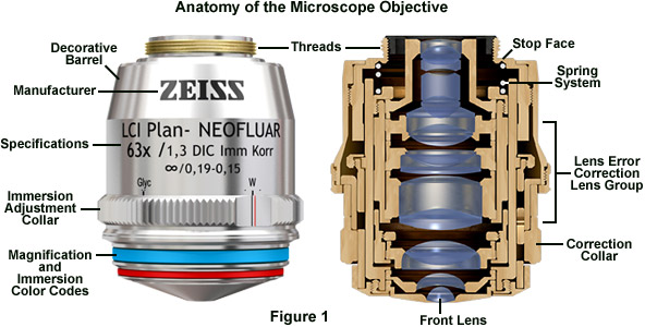
Engravings found on the condenser housing include its type (achromatic, aplanatic, etc.), the numerical aperture, and a graded scale that indicates the approximate adjustment (size) of the aperture diaphragm. Condensers with numerical apertures above 0.95 perform best when a drop of oil is applied to their upper lens in contact with the undersurface of the specimen slide. This ensures that oblique light rays emanating from the condenser are not reflected from underneath the slide, but are directed into the specimen. In practice, this can become tedious and is not commonly done in routine microscopy, but is essential when working at high resolutions and for accurate imaging using high-power (and numerical aperture) objectives.
At right, shown is the effect of 1 wave P-V of defocus on the image of an object that is not the standard MTF pattern, but one in which bar width is oriented horizontally, with the line width changing continuously according to the spatial frequency. Top image (A) is aberration-free, and bottom (B) defocused one. If the aberration is large enough - in the case of defocus ~0.9 wave P-V or larger - image of such object will show contrast reversal - where bright lines become dark and vice versa - indicated by the OTF, but not the MTF. The reason was immediately apparent from the PSF intensity distribution for 1 wave of defocus, developing dark circle (minima) at the center of the pattern. Hence, MTF does provide information on contrast transfer, but not on the image itself. To reconstruct the image, we need OTF. This, however. may have significance only with large aberrations, generally about 1 wave P-V and larger (a few more examples at ). OTF for smaller aberrations does not fall below zero, thus there is no contrast reversal to affect image. As plot at right show, the standard MTF output by OSLO (dashed) does not equal the absolute value of OTF, indicating that MTF plot may vary somewhat depending on the algorithm applied. If defined as the absolute value of OTF magnitude, MTF should continue through the red plot section. INSET C: In addition to phase shift, if PSF intensity is varying radially it will also cause different contrast transfer for different orientations of the PSF relative to MTF pattern. A complete MTF integral has radial component, thus it integrates for all orientations of the PSF relative to the line pattern. Graphically, it is represented by a volume figure, formed by continuous change of the integration angle (i.e. pattern orientation) through a full circle, or 2π radians (right). This volume may be looked at as a total contrast, transfer. For radially symmetrical aberrations, like spherical or defocus, there is no variation in contrast transfer with orientation, and it is fully represented by any single orientation, i.e. 2-D MTF. For radially asymmetrical aberrations, like coma or astigmatism, the transfer, hence also the MTF volume cross section profile, changes with the orientation, forming rotationally asymmetrical 3-D figure. The default representation is often to show MTF for sagittal (perpendicular to MTF bar orientation) and tangential (along bar orientation) PSF orientation. This works well with coma, where it assesses the two limiting effects, the minimum (the latter) and maximum (former), giving a good idea of the average effect on contrast transfer. With astigmatism, however, which at the minimum variance focus causes a cross-like PSF deformation, with 0 (π) and π/2 (3π/2) PSF rotation producing the same effect, while the maximum effect on MTF contrast transfer is for π/4 (+π) PSF rotations. Contrast transfer for all PSF orientations also can be azimuthally averaged, giving mean contrast transfer for the aberration. INSET D: Note that the graph on top represents monochromatic MTF (as indicated by the cutoff frequency 1/λF). Polychromatic MTF cutoff frequency - and to a slight extent, the overall shape - is determined by the combined PSF intensity distribution within the wavelength range. As large inset at right illustrates, while PSF for individual wavelengths differ significantly at the ends of given spectral range (first minima being at 1.22λF), when combined they nearly offset around the central wavelength's PSF. Actual PSFs for different wavelengths also normally differ in their intensity, both emitted by object and perceived by eye, which may affect contrast transfer by giving to it bias toward the wavelength of maximum intensity, since the intensity distribution loses the symmetry around central wavelength). There is little difference between centered monochromatic (green) and full-range polychromatic PSF (black), thus also MTF, regardless of the sensitivity mode. The PSF differ mainly in the ring area (photopic vs. even spectrum, small inset), and with MTF it is limited to the value of cutoff frequency, which is for polychromatic light determined by that for the shortest wavelength. This is based on the formalism describing polychromatic contrast transfer as the average sum of the transfer c for given frequency ν at each of i wavelengths, MTF(ν)=Σc(ν)i/i. As a result, long and short wavelengths nearly offset each other for the most of frequency range, with the resulting polychromatic MTF for the range gravitating toward that of the mid-wavelength; some residual contrast transfer extends beyond that for the central wavelength, not significantly influenced by eye sensitivity factor. While the nominal cutoff frequency for polychromatic MTF equals that of the shortest wavelength, it actual contrast transfer is much closer to that of the central wavelength.
DEFOCUS: 1/4 and 1/2 wave P-V. Doubling the error halves the peak PSF intensity (Strehl), but the average contrast loss is three times greater (20% vs. 60%, given as a ratio number by the differential between the Strehl and 1). Note that the Strehl for 1/4 wave WFE of defocus is slightly higher than 0.80. PRIMARY SPHERICAL ABERRATION: 1/4 wave and 1/2 wave P-V errors have nearly identical effect on the PSF maximum as with defocus, but the more widely spread energy causes more of contrast loss at the lower frequencies, while the smaller central maxima results in somewhat better transfer at mid-to-high frequencies. The transfer is again inferior near the cutoff due to the smaller bright core with defocus. Being close to zero, the cutoff frequency for 1/2 wave P-V is about 20% lower in field conditions. PRIMARY COMA: 0.42 and 0.84 wave P-V have similar effect on the PSF peak value as 1/4 and 1/2 wave P-V of defocus or primary spherical. However, the actual contrast transfer varies significantly with the orientation of the asymmetrical aberrated pattern relative to MTF bars. It is the worst when the blur length is perpendicular to the bars (red), and the best when blur length has the same orientation (green). MTF plots hitting zero contrast near the cutoff and bouncing after, indicate contrast reversal. PRIMARY ASTIGMATISM: The effect of 0.37 and 0.74 wave P-V is similar to 1/4 and 1/2 wave of defocus in that the energy spread out of the Airy disc is mostly contained closer to central maxima, resulting in less of contrast loss at low frequencies. Unlike defocus, does not change radial symmetry of PSF, astigmatism gives to it cross-like shape which, similarly to coma's asymmetry, gives the best contrast transfer when cross orientation is identical to that of the bars (green) and the worst when it is at 45° angle. TURNED EDGE: 2.5 waves P-V is needed that turned edge starting at 95% the radius to lower the Strehl to 0.80. Lost energy is evenly spread wide out (the abrupt initial contrast loss ending at about 1/40 frequency indicates the radius of this spread as 40 times the cutoff frequency, or 40λF - over 30 times the Airy disc radius). Odd but expected TE property - due to the relatively small affected area (the RMS for 0.80 Strehl is whooping 0.28 wave) - is that increasing the aberration does almost no additional damage. ROUGHNESS: ~1/14 and ~1/7 wave RMS of roughness producing asymmetric PSF pattern, thus having contrast transfer vary with its orientation relative to MTF bars. Due to the random nature of the aberration, the P-V wavefront error can vary significantly for any given RMS/Strehl level. IHere, the P-V error ranges from -0.169 (blue speck on the wavefront map) to 0.374, and -345 to 0.745, respectively. RMS error also may not be as reliably related to the Strehl as with most other aberrations. PINCHING: 0.37 and 0.74 wave P-V of wavefront deformation caused by edge pinching at a three 120° separated points has the typical 3-sided symmetry (trefoil). the aberration is radially asymmetric, causing the contrast transfer to vary between the maximum (red, for zero, 120° and 240° orientation angle) and minimum (60°, 180° and 300° orientation). Other forms do occur, with or without some form of symmetry. About 30% of the frequency range toward high end shows contrast reversal. TUBE CURRENTS: 3/4 and 1.5 wave P-V wavefront error caused by tube currents affecting end 30% of the wavefront radius. Energy spreads mainly in the direction of wavefront deformation. Similarly to the TE, the RMS error (0.106 and 0.212, respectively) is disproportionally large vs. Strehl, and doubling the error has relatively small effect. Contrast transfer is the worst when the energy spreads orthogonally to MTF bars; for the aberrated energy spread having the same orientation as MTF bars is perfect (green). SEEING ERROR: Averaged PSF/MTF effect of ~1/14 and ~1/7 wave RMS of atmospheric turbulence. The P-V error can vary substantially (here is 0.43 and 0.86 wave, respectively). Seeing error fluctuates constantly around the average, as do the corresponding image contrast and resolution. Larger seeing errors (1/7 wave RMS is rather common with medium size apertures) reduces contrast level to that similar to twice smaller aperture for low-to-mid frequencies, with some high-frequency transfer (iincluding limiting resolution) advantage remaining. MTF contrast transfer generalized to the RMS wavefront error alone, regardless of the type of aberration is, as shown by Bob Shannon, given by a product of aberration-free MTF and the Aberration Transfer Function [ATF=1-(ω/0.18)2(1-4(ν-0.5)2), where ω is the RMS wavefront error in units of wavelength, and v is the normalized spatial frequency; not to confuse with the Amplitude Transfer Function - this is the only place where the Aberration Transfer Function is mentioned] for any given level of the RMS error, and aberration-free MTF, as illustrated at left for selected levels of RMS wavefront error (ω). It clearly shows that contrast transfer does not drop linearly, but exponentially with the increase in the RMS error. While the contrast loss is still negligible for ω=0.037 (1/8 wave P-V of primary spherical level), it is several times larger at the error doubled. Another 50% higher error, to 0.10 wave RMS, nearly doubles the loss, but yet another 50% increase, to 0.149, more than doubles the entire contrast loss at ω=0.10. Also, with the increase in error magnitude, maximum contrast drop gradually shifts from the lower mid frequencies to the mid frequencies. With small-to-moderate RMS wavefront errors, this generalized MTF can be assumed to also represent the averaged contrast drop for a given RMS error for asymmetrical aberrations, like coma and astigmatism, or for irregular wavefront deformations characteristic of the actual systems (due to their asymmetric form, such aberrations have contrast transfer varying with the MTF orientation). However, since the differences in contrast transfer over MTF frequency sub ranges for different aberration forms generally increase with the wavefront error - especially as it exceeds 0.15 wave RMS - the usefulness of this generalized MTF approach diminishes going beyond that level.
Research-level microscopes also contain one of several light-conditioning devices that are often positioned between the illuminator and condenser, and a complementary detector or filtering device that is inserted between the objective and the eyepiece or camera. The conditioning device(s) and detector work together to modify image contrast as a function of spatial frequency, phase, polarization, absorption, fluorescence, off-axis illumination, and/or other properties of the specimen and illumination technique. Even without the addition of specific devices to condition illumination and filter image-forming waves, some degree of natural filtering occurs with even the most basic microscope configuration.
The first stage of the microscope optical train (and perhaps the most neglected) is the lamphouse, which contains the lamp and collector lens system. This unit is responsible for establishing the primary illumination conditions for the microscope. Light emitted by a tungsten-halogen or arc-discharge is passed through the collector lens system and the filament or arc is focused onto the front focal plane of the condenser (objective in reflected epi-fluorescence). The first image plane in the microscope optical train occurs at the position of the field diaphragm. Thus, the lamphouse coupled with the field diaphragm produces the necessary illumination pattern to sufficiently image specimens in a wide variety of imaging modes. In the optical microscope, conjugate planes are imaged into each other and can collectively be observed while examining a specimen in the eyepieces. The field iris diaphragm, adjacent to the lamp collector lens, is imaged sharply into the same plane as the specimen by the microscope condenser. Images of both the field diaphragm and the specimen are formed in the intermediate image plane by the objective and are projected into the fixed field diaphragm of the eyepiece, where the focusing reticle is located. Subsequently, the eyepiece (in conjunction with the observer's eye) forms images of all three previous image planes on the sensor surface of an imaging system or the retina of a human eye. The field diaphragm, specimen, intermediate image, and retina all constitute a set of conjugate image planes, spaced throughout the microscope optical train, which appear simultaneously in focus.
An actual object that comes very close to the standardized MTF scenario is a pair of nearly equally bright stars at the optimum brightness level. Resolution-wise, the MTF limiting resolution (cutoff frequency) is nearly identical to the empirical Dawes' limit in double star observing. However, for pairs farther from the optimum brightness level, or, especially, pairs with significant difference in brightness, the resolution limit is lower, or much lower. Still, despite the MTF being standardized to a single object form sample and brightness level, it is considered to be a reliable general indicator of the effect of wavefront aberrations - or any other factor affecting wave interference in the focal zone - on image quality. As mentioned, given relatively low RMS wavefront level of any aberration will result in near-identical overall contrast loss, but the specifics will vary somewhat. FIG. 101 illustrates variations in the aberrated PSF (left) and MTF (right) for common wavefront aberrations of 1/13.4 and 1/6.7 wave RMS (graphs generated by Aberrator freeware, Cor Berrevoets). FIGURE 101: PSF and MTF plots for clear aberration-free aperture (black), and aberrated (red) at the 0.80 Strehl level, and that wavefront error doubled. DEFOCUS: 1/4 and 1/2 wave P-V. Doubling the error halves the peak PSF intensity (Strehl), but the average contrast loss is three times greater (20% vs. 60%, given as a ratio number by the differential between the Strehl and 1). Note that the Strehl for 1/4 wave WFE of defocus is slightly higher than 0.80. PRIMARY SPHERICAL ABERRATION: 1/4 wave and 1/2 wave P-V errors have nearly identical effect on the PSF maximum as with defocus, but the more widely spread energy causes more of contrast loss at the lower frequencies, while the smaller central maxima results in somewhat better transfer at mid-to-high frequencies. The transfer is again inferior near the cutoff due to the smaller bright core with defocus. Being close to zero, the cutoff frequency for 1/2 wave P-V is about 20% lower in field conditions. PRIMARY COMA: 0.42 and 0.84 wave P-V have similar effect on the PSF peak value as 1/4 and 1/2 wave P-V of defocus or primary spherical. However, the actual contrast transfer varies significantly with the orientation of the asymmetrical aberrated pattern relative to MTF bars. It is the worst when the blur length is perpendicular to the bars (red), and the best when blur length has the same orientation (green). MTF plots hitting zero contrast near the cutoff and bouncing after, indicate contrast reversal. PRIMARY ASTIGMATISM: The effect of 0.37 and 0.74 wave P-V is similar to 1/4 and 1/2 wave of defocus in that the energy spread out of the Airy disc is mostly contained closer to central maxima, resulting in less of contrast loss at low frequencies. Unlike defocus, does not change radial symmetry of PSF, astigmatism gives to it cross-like shape which, similarly to coma's asymmetry, gives the best contrast transfer when cross orientation is identical to that of the bars (green) and the worst when it is at 45° angle. TURNED EDGE: 2.5 waves P-V is needed that turned edge starting at 95% the radius to lower the Strehl to 0.80. Lost energy is evenly spread wide out (the abrupt initial contrast loss ending at about 1/40 frequency indicates the radius of this spread as 40 times the cutoff frequency, or 40λF - over 30 times the Airy disc radius). Odd but expected TE property - due to the relatively small affected area (the RMS for 0.80 Strehl is whooping 0.28 wave) - is that increasing the aberration does almost no additional damage. ROUGHNESS: ~1/14 and ~1/7 wave RMS of roughness producing asymmetric PSF pattern, thus having contrast transfer vary with its orientation relative to MTF bars. Due to the random nature of the aberration, the P-V wavefront error can vary significantly for any given RMS/Strehl level. IHere, the P-V error ranges from -0.169 (blue speck on the wavefront map) to 0.374, and -345 to 0.745, respectively. RMS error also may not be as reliably related to the Strehl as with most other aberrations. PINCHING: 0.37 and 0.74 wave P-V of wavefront deformation caused by edge pinching at a three 120° separated points has the typical 3-sided symmetry (trefoil). the aberration is radially asymmetric, causing the contrast transfer to vary between the maximum (red, for zero, 120° and 240° orientation angle) and minimum (60°, 180° and 300° orientation). Other forms do occur, with or without some form of symmetry. About 30% of the frequency range toward high end shows contrast reversal. TUBE CURRENTS: 3/4 and 1.5 wave P-V wavefront error caused by tube currents affecting end 30% of the wavefront radius. Energy spreads mainly in the direction of wavefront deformation. Similarly to the TE, the RMS error (0.106 and 0.212, respectively) is disproportionally large vs. Strehl, and doubling the error has relatively small effect. Contrast transfer is the worst when the energy spreads orthogonally to MTF bars; for the aberrated energy spread having the same orientation as MTF bars is perfect (green). SEEING ERROR: Averaged PSF/MTF effect of ~1/14 and ~1/7 wave RMS of atmospheric turbulence. The P-V error can vary substantially (here is 0.43 and 0.86 wave, respectively). Seeing error fluctuates constantly around the average, as do the corresponding image contrast and resolution. Larger seeing errors (1/7 wave RMS is rather common with medium size apertures) reduces contrast level to that similar to twice smaller aperture for low-to-mid frequencies, with some high-frequency transfer (iincluding limiting resolution) advantage remaining. MTF contrast transfer generalized to the RMS wavefront error alone, regardless of the type of aberration is, as shown by Bob Shannon, given by a product of aberration-free MTF and the Aberration Transfer Function [ATF=1-(ω/0.18)2(1-4(ν-0.5)2), where ω is the RMS wavefront error in units of wavelength, and v is the normalized spatial frequency; not to confuse with the Amplitude Transfer Function - this is the only place where the Aberration Transfer Function is mentioned] for any given level of the RMS error, and aberration-free MTF, as illustrated at left for selected levels of RMS wavefront error (ω). It clearly shows that contrast transfer does not drop linearly, but exponentially with the increase in the RMS error. While the contrast loss is still negligible for ω=0.037 (1/8 wave P-V of primary spherical level), it is several times larger at the error doubled. Another 50% higher error, to 0.10 wave RMS, nearly doubles the loss, but yet another 50% increase, to 0.149, more than doubles the entire contrast loss at ω=0.10. Also, with the increase in error magnitude, maximum contrast drop gradually shifts from the lower mid frequencies to the mid frequencies. With small-to-moderate RMS wavefront errors, this generalized MTF can be assumed to also represent the averaged contrast drop for a given RMS error for asymmetrical aberrations, like coma and astigmatism, or for irregular wavefront deformations characteristic of the actual systems (due to their asymmetric form, such aberrations have contrast transfer varying with the MTF orientation). However, since the differences in contrast transfer over MTF frequency sub ranges for different aberration forms generally increase with the wavefront error - especially as it exceeds 0.15 wave RMS - the usefulness of this generalized MTF approach diminishes going beyond that level. ◄ 6.5. Strehl ratio ▐ 6.6.1. MTF - aberration compounding, CCD, limitations ► Home | Comments
The optical components contained within modern microscopes are mounted on a stable, ergonomically designed base that allows rapid exchange, precision centering, and careful alignment between those assemblies that are optically interdependent. Together, the optical and mechanical components of the microscope, including the mounted specimen on a glass microslide and coverslip, form an optical train with a central axis that traverses the microscope base and stand. The microscope optical train typically consists of an illuminator (including the light source and collector lens), a substage condenser that serves to prepare illumination for imaging, specimen, objective, eyepiece, and detector, which is either some form of camera or the observer's eye.
It is important to understand that the MTF graph, such as the one above, does not set absolute values for the contrast drop, or limit to resolution. Both are strictly applicable only to the particular MTF object form used for its calculation: a sinusoidal pattern of bright lines on dark background, λF/2ν wide linearly, F being the focal ratio f/D (i.e. linear width of the bright line at resolution limit is λF/2, or nearly one fifth of Airy disc diameter). Actual contrast drop-off and limiting resolution will vary with the specific properties of details observed, background, and peculiarities of eye perception, or detector properties. For non-continuous patterns, sinusoidal, square-wave, or others, contrast transfer will generally increase with the reduction in the number of lines (FIG. 103). One example is the resolution threshold for low-contrast MTF-like planetary details which is, according to the LCB threshold level in FIG. 100, approximately half of that for brightly illuminated contrasty object. Another is a dark line on light background, which can be detected at an angular width several times smaller than the angular diffraction resolution limit for point-images of ~λ/D radians, because it is the Edge Spread Function, not the PSF, that is applicable in determining its diffraction intensity distribution. An actual object that comes very close to the standardized MTF scenario is a pair of nearly equally bright stars at the optimum brightness level. Resolution-wise, the MTF limiting resolution (cutoff frequency) is nearly identical to the empirical Dawes' limit in double star observing. However, for pairs farther from the optimum brightness level, or, especially, pairs with significant difference in brightness, the resolution limit is lower, or much lower. Still, despite the MTF being standardized to a single object form sample and brightness level, it is considered to be a reliable general indicator of the effect of wavefront aberrations - or any other factor affecting wave interference in the focal zone - on image quality. As mentioned, given relatively low RMS wavefront level of any aberration will result in near-identical overall contrast loss, but the specifics will vary somewhat. FIG. 101 illustrates variations in the aberrated PSF (left) and MTF (right) for common wavefront aberrations of 1/13.4 and 1/6.7 wave RMS (graphs generated by Aberrator freeware, Cor Berrevoets). FIGURE 101: PSF and MTF plots for clear aberration-free aperture (black), and aberrated (red) at the 0.80 Strehl level, and that wavefront error doubled. DEFOCUS: 1/4 and 1/2 wave P-V. Doubling the error halves the peak PSF intensity (Strehl), but the average contrast loss is three times greater (20% vs. 60%, given as a ratio number by the differential between the Strehl and 1). Note that the Strehl for 1/4 wave WFE of defocus is slightly higher than 0.80. PRIMARY SPHERICAL ABERRATION: 1/4 wave and 1/2 wave P-V errors have nearly identical effect on the PSF maximum as with defocus, but the more widely spread energy causes more of contrast loss at the lower frequencies, while the smaller central maxima results in somewhat better transfer at mid-to-high frequencies. The transfer is again inferior near the cutoff due to the smaller bright core with defocus. Being close to zero, the cutoff frequency for 1/2 wave P-V is about 20% lower in field conditions. PRIMARY COMA: 0.42 and 0.84 wave P-V have similar effect on the PSF peak value as 1/4 and 1/2 wave P-V of defocus or primary spherical. However, the actual contrast transfer varies significantly with the orientation of the asymmetrical aberrated pattern relative to MTF bars. It is the worst when the blur length is perpendicular to the bars (red), and the best when blur length has the same orientation (green). MTF plots hitting zero contrast near the cutoff and bouncing after, indicate contrast reversal. PRIMARY ASTIGMATISM: The effect of 0.37 and 0.74 wave P-V is similar to 1/4 and 1/2 wave of defocus in that the energy spread out of the Airy disc is mostly contained closer to central maxima, resulting in less of contrast loss at low frequencies. Unlike defocus, does not change radial symmetry of PSF, astigmatism gives to it cross-like shape which, similarly to coma's asymmetry, gives the best contrast transfer when cross orientation is identical to that of the bars (green) and the worst when it is at 45° angle. TURNED EDGE: 2.5 waves P-V is needed that turned edge starting at 95% the radius to lower the Strehl to 0.80. Lost energy is evenly spread wide out (the abrupt initial contrast loss ending at about 1/40 frequency indicates the radius of this spread as 40 times the cutoff frequency, or 40λF - over 30 times the Airy disc radius). Odd but expected TE property - due to the relatively small affected area (the RMS for 0.80 Strehl is whooping 0.28 wave) - is that increasing the aberration does almost no additional damage. ROUGHNESS: ~1/14 and ~1/7 wave RMS of roughness producing asymmetric PSF pattern, thus having contrast transfer vary with its orientation relative to MTF bars. Due to the random nature of the aberration, the P-V wavefront error can vary significantly for any given RMS/Strehl level. IHere, the P-V error ranges from -0.169 (blue speck on the wavefront map) to 0.374, and -345 to 0.745, respectively. RMS error also may not be as reliably related to the Strehl as with most other aberrations. PINCHING: 0.37 and 0.74 wave P-V of wavefront deformation caused by edge pinching at a three 120° separated points has the typical 3-sided symmetry (trefoil). the aberration is radially asymmetric, causing the contrast transfer to vary between the maximum (red, for zero, 120° and 240° orientation angle) and minimum (60°, 180° and 300° orientation). Other forms do occur, with or without some form of symmetry. About 30% of the frequency range toward high end shows contrast reversal. TUBE CURRENTS: 3/4 and 1.5 wave P-V wavefront error caused by tube currents affecting end 30% of the wavefront radius. Energy spreads mainly in the direction of wavefront deformation. Similarly to the TE, the RMS error (0.106 and 0.212, respectively) is disproportionally large vs. Strehl, and doubling the error has relatively small effect. Contrast transfer is the worst when the energy spreads orthogonally to MTF bars; for the aberrated energy spread having the same orientation as MTF bars is perfect (green). SEEING ERROR: Averaged PSF/MTF effect of ~1/14 and ~1/7 wave RMS of atmospheric turbulence. The P-V error can vary substantially (here is 0.43 and 0.86 wave, respectively). Seeing error fluctuates constantly around the average, as do the corresponding image contrast and resolution. Larger seeing errors (1/7 wave RMS is rather common with medium size apertures) reduces contrast level to that similar to twice smaller aperture for low-to-mid frequencies, with some high-frequency transfer (iincluding limiting resolution) advantage remaining. MTF contrast transfer generalized to the RMS wavefront error alone, regardless of the type of aberration is, as shown by Bob Shannon, given by a product of aberration-free MTF and the Aberration Transfer Function [ATF=1-(ω/0.18)2(1-4(ν-0.5)2), where ω is the RMS wavefront error in units of wavelength, and v is the normalized spatial frequency; not to confuse with the Amplitude Transfer Function - this is the only place where the Aberration Transfer Function is mentioned] for any given level of the RMS error, and aberration-free MTF, as illustrated at left for selected levels of RMS wavefront error (ω). It clearly shows that contrast transfer does not drop linearly, but exponentially with the increase in the RMS error. While the contrast loss is still negligible for ω=0.037 (1/8 wave P-V of primary spherical level), it is several times larger at the error doubled. Another 50% higher error, to 0.10 wave RMS, nearly doubles the loss, but yet another 50% increase, to 0.149, more than doubles the entire contrast loss at ω=0.10. Also, with the increase in error magnitude, maximum contrast drop gradually shifts from the lower mid frequencies to the mid frequencies. With small-to-moderate RMS wavefront errors, this generalized MTF can be assumed to also represent the averaged contrast drop for a given RMS error for asymmetrical aberrations, like coma and astigmatism, or for irregular wavefront deformations characteristic of the actual systems (due to their asymmetric form, such aberrations have contrast transfer varying with the MTF orientation). However, since the differences in contrast transfer over MTF frequency sub ranges for different aberration forms generally increase with the wavefront error - especially as it exceeds 0.15 wave RMS - the usefulness of this generalized MTF approach diminishes going beyond that level. ◄ 6.5. Strehl ratio ▐ 6.6.1. MTF - aberration compounding, CCD, limitations ► Home | Comments
TURNED EDGE: 2.5 waves P-V is needed that turned edge starting at 95% the radius to lower the Strehl to 0.80. Lost energy is evenly spread wide out (the abrupt initial contrast loss ending at about 1/40 frequency indicates the radius of this spread as 40 times the cutoff frequency, or 40λF - over 30 times the Airy disc radius). Odd but expected TE property - due to the relatively small affected area (the RMS for 0.80 Strehl is whooping 0.28 wave) - is that increasing the aberration does almost no additional damage. ROUGHNESS: ~1/14 and ~1/7 wave RMS of roughness producing asymmetric PSF pattern, thus having contrast transfer vary with its orientation relative to MTF bars. Due to the random nature of the aberration, the P-V wavefront error can vary significantly for any given RMS/Strehl level. IHere, the P-V error ranges from -0.169 (blue speck on the wavefront map) to 0.374, and -345 to 0.745, respectively. RMS error also may not be as reliably related to the Strehl as with most other aberrations. PINCHING: 0.37 and 0.74 wave P-V of wavefront deformation caused by edge pinching at a three 120° separated points has the typical 3-sided symmetry (trefoil). the aberration is radially asymmetric, causing the contrast transfer to vary between the maximum (red, for zero, 120° and 240° orientation angle) and minimum (60°, 180° and 300° orientation). Other forms do occur, with or without some form of symmetry. About 30% of the frequency range toward high end shows contrast reversal. TUBE CURRENTS: 3/4 and 1.5 wave P-V wavefront error caused by tube currents affecting end 30% of the wavefront radius. Energy spreads mainly in the direction of wavefront deformation. Similarly to the TE, the RMS error (0.106 and 0.212, respectively) is disproportionally large vs. Strehl, and doubling the error has relatively small effect. Contrast transfer is the worst when the energy spreads orthogonally to MTF bars; for the aberrated energy spread having the same orientation as MTF bars is perfect (green). SEEING ERROR: Averaged PSF/MTF effect of ~1/14 and ~1/7 wave RMS of atmospheric turbulence. The P-V error can vary substantially (here is 0.43 and 0.86 wave, respectively). Seeing error fluctuates constantly around the average, as do the corresponding image contrast and resolution. Larger seeing errors (1/7 wave RMS is rather common with medium size apertures) reduces contrast level to that similar to twice smaller aperture for low-to-mid frequencies, with some high-frequency transfer (iincluding limiting resolution) advantage remaining. MTF contrast transfer generalized to the RMS wavefront error alone, regardless of the type of aberration is, as shown by Bob Shannon, given by a product of aberration-free MTF and the Aberration Transfer Function [ATF=1-(ω/0.18)2(1-4(ν-0.5)2), where ω is the RMS wavefront error in units of wavelength, and v is the normalized spatial frequency; not to confuse with the Amplitude Transfer Function - this is the only place where the Aberration Transfer Function is mentioned] for any given level of the RMS error, and aberration-free MTF, as illustrated at left for selected levels of RMS wavefront error (ω). It clearly shows that contrast transfer does not drop linearly, but exponentially with the increase in the RMS error. While the contrast loss is still negligible for ω=0.037 (1/8 wave P-V of primary spherical level), it is several times larger at the error doubled. Another 50% higher error, to 0.10 wave RMS, nearly doubles the loss, but yet another 50% increase, to 0.149, more than doubles the entire contrast loss at ω=0.10. Also, with the increase in error magnitude, maximum contrast drop gradually shifts from the lower mid frequencies to the mid frequencies. With small-to-moderate RMS wavefront errors, this generalized MTF can be assumed to also represent the averaged contrast drop for a given RMS error for asymmetrical aberrations, like coma and astigmatism, or for irregular wavefront deformations characteristic of the actual systems (due to their asymmetric form, such aberrations have contrast transfer varying with the MTF orientation). However, since the differences in contrast transfer over MTF frequency sub ranges for different aberration forms generally increase with the wavefront error - especially as it exceeds 0.15 wave RMS - the usefulness of this generalized MTF approach diminishes going beyond that level.
One of the most important criteria to be considered in the purchase of an optical microscope is the required field of application. Another, perhaps equally important, is the state of (aberration) correction of the optical components, in particular, the objectives. Microscope objectives are perhaps the most important components of an optical microscope because they are responsible for primary image formation and play a central role in determining the quality of images that the microscope is capable of producing. Objectives are also instrumental in determining the magnification of a particular specimen and the resolution under which fine specimen detail can be observed and recorded using the microscope. The objective is the most difficult component of an optical microscope to design and manufacture, and is the first component that light encounters as it proceeds from the specimen to the image plane.


 Ms.Cici
 8618319014500