
Ultra Thin Mirror - thin mirror
Normal optical microscopes can magnify up to 1500× with a theoretical resolution of −0.2 μm. The lenses can be quite complicated and are composed of multiple elements to reduce aberrations. Microscope objective lenses are particularly important as they primarily gather light from the specimen. Three parameters describe microscope objectives: the numerical aperture (NA), the magnification (m), and the working distance. The NA is related to the light gathering ability of a lens and is obtained using the angle of acceptance θ formed by the maximum cone of rays focusing on the specimen (see Figure 3a) and is given by NA = n sin α, where n is the refractive index of the medium between the lens and the specimen and . As the angle of acceptance given by θ increases, NA becomes larger and more light is gathered from a smaller focal region giving higher resolution. A 0.75 NA objective gives more detail than a 0.10 NA objective.
Your password must be updated. Follow the ‘Lost password?’ prompt below to reset your credentials. If you have any questions, please contact Customer Service at 1-800-MAC-TOOLS for assistance.
Modulated in much the same manner as radio waves, its high frequencies can handle far more intelligence than any microwave beam. Each five-thousandth-of-a- ...
numerical aperture: a number or measure that expresses the ability of a lens to resolve fine detail in an object being observed. Derived by mathematical formula NA = n sin α, where n is the refractive index of the medium between the lens and the specimen and
Focal length of a microscopecalculator
Buy and save on Nora Lighting NP-323 6" Fresnel Lens with Plastic Trim and Bracket. Best Prices on Nora Lighting Fresnel Lenses.
Focalpointof microscope
where do and di are the object and image distances, respectively, for the objective lens as labeled in Figure 2. The object distance is given to be do=6.20 mm, but the image distance di is not known. Isolating di, we have
Although the eye is marvelous in its ability to see objects large and small, it obviously has limitations to the smallest details it can detect. Human desire to see beyond what is possible with the naked eye led to the use of optical instruments. In this section we will examine microscopes, instruments for enlarging the detail that we cannot see with the unaided eye. The microscope is a multiple-element system having more than a single lens or mirror. (See Figure 1.) A microscope can be made from two convex lenses. The image formed by the first element becomes the object for the second element. The second element forms its own image, which is the object for the third element, and so on. Ray tracing helps to visualize the image formed. If the device is composed of thin lenses and mirrors that obey the thin lens equations, then it is not difficult to describe their behavior numerically.
compound microscope: a microscope constructed from two convex lenses, the first serving as the ocular lens(close to the eye) and the second serving as the objective lens
As of Tuesday, 19/11/2024, 34000.55 US dollars (USD) is equal to 47465.69 Canadian dollars (CAD). See the real-time conversion rate and historical exchange rate ...
When using a microscope we do not see the entire extent of the sample. Depending on the eyepiece and objective lens we see a restricted region which we say is the field of view. The objective is then manipulated in two-dimensions above the sample to view other regions of the sample. Electronic scanning of either the objective or the sample is used in scanning microscopy. The image formed at each point during the scanning is combined using a computer to generate an image of a larger region of the sample at a selected magnification.
Calculate the magnification of an object placed 6.20 mm from a compound microscope that has a 6.00 mm focal length objective and a 50.0 mm focal length eyepiece. The objective and eyepiece are separated by 23.0 cm.
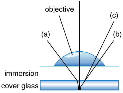
Can the NA be larger than 1.00? The answer is ‘yes’ if we use immersion lenses in which a medium such as oil, glycerine or water is placed between the objective and the microscope cover slip. This minimizes the mismatch in refractive indices as light rays go through different media, generally providing a greater light-gathering ability and an increase in resolution. Figure 5 shows light rays when using air and immersion lenses.
Focal length ofobjective lens in compoundmicroscope
Feb 26, 2024 — You may want to use isopropyl alcohol applied to a q-tip to clean out any debris from the threads. Follow up with a very thin layer of wax to ...
Design Letters - The Classic Collection Trinkflasche - G - weiß. 10,95 € inkl. MwSt. ... Die ABC-Wasserflasche von Design Letters im Stil von Arne Jacobsen ziert ...
Focal length microscopedefinition
We normally associate microscopes with visible light but x ray and electron microscopes provide greater resolution. The focusing and basic physics is the same as that just described, even though the lenses require different technology. The electron microscope requires vacuum chambers so that the electrons can proceed unheeded. Magnifications of 50 million times provide the ability to determine positions of individual atoms within materials. An electron microscope is shown in Figure 7.
The term f/# in general is called the f-number and is used to denote the light per unit area reaching the image plane. In photography, an image of an object at infinity is formed at the focal point and the f-number is given by the ratio of the focal length f of the lens and the diameter D of the aperture controlling the light into the lens (see Figure 3b). If the acceptance angle is small the NA of the lens can also be used as given below.
Working distanceof40x objective
Your personal information will be handled in accordance with our Privacy Notice (https://www.stanleyblackanddecker.com/privacy-policy). By entering your email address you agree to receive marketing emails from Mac Tools® with news, special offers, promotions, and other information. You may opt out of these emails at any time. Contact us by filling in our Privacy Inquiry Form (https://privacyportal-eu.onetrust.com/webform/049d4fb1-d34c-492a-b8cb-90a2427fc05e/8231fc5f-c921-4ad7-96bd-f95c94840a79) or sending mail to 701 E. Joppa Road, Towson, Maryland, 21286 for more information.
Define working distance inmicroscope
Look through a clear glass or plastic bottle and describe what you see. Now fill the bottle with water and describe what you see. Use the water bottle as a lens to produce the image of a bright object and estimate the focal length of the water bottle lens. How is the focal length a function of the depth of water in the bottle?
Pressure Gauges · Air Ride Kits · Air Tanks ... Wera Hex-Plus 9pc Hex Key Set - Metric ... Klein Tools 11-Key Pro Folding Hex Key Set - SAE.
Advanced technologies such as the Internet of Things, industrial data, advanced manufacturing, robotics, 3D printing, blockchain and artificial intelligence ...
5. (a) +18.3 cm (on the eyepiece side of the objective lens); (b) −60.0; (c) −11.3 cm (on the objective side of the eyepiece); (d) +6.67; (e) −400
This situation is similar to that shown in Figure 2. To find the overall magnification, we must find the magnification of the objective, then the magnification of the eyepiece. This involves using the thin lens equation.
Both the objective and the eyepiece contribute to the overall magnification, which is large and negative, consistent with Figure 2, where the image is seen to be large and inverted. In this case, the image is virtual and inverted, which cannot happen for a single element (case 2 and case 3 images for single elements are virtual and upright). The final image is 367 mm (0.367 m) to the left of the eyepiece. Had the eyepiece been placed farther from the objective, it could have formed a case 1 image to the right. Such an image could be projected on a screen, but it would be behind the head of the person in the figure and not appropriate for direct viewing. The procedure used to solve this example is applicable in any multiple-element system. Each element is treated in turn, with each forming an image that becomes the object for the next element. The process is not more difficult than for single lenses or mirrors, only lengthier.
May 19, 2022 — Anti-reflective coating glasses reduce glare and reflections on the surface of your lenses, improving their vision-correcting ability.
Focal length of a microscopeformula
Jun 24, 2024 — USEEPlus is a control software for MFI devices It is connected to the mobile phone via USB You can view your phone's photo album files ...
We do not use our eyes to form images; rather images are recorded electronically and displayed on computers. In fact observing and saving images formed by optical microscopes on computers is now done routinely. Video recordings of what occurs in a microscope can be made for viewing by many people at later dates. Physics provides the science and tools needed to generate the sequence of time-lapse images of meiosis similar to the sequence sketched in Figure 8.
What isfocal length oflens
As the f-number decreases, the camera is able to gather light from a larger angle, giving wide-angle photography. As usual there is a trade-off. A greater f/# means less light reaches the image plane. A setting of f/16 usually allows one to take pictures in bright sunlight as the aperture diameter is small. In optical fibers, light needs to be focused into the fiber. Figure 4 shows the angle used in calculating the NA of an optical fiber.
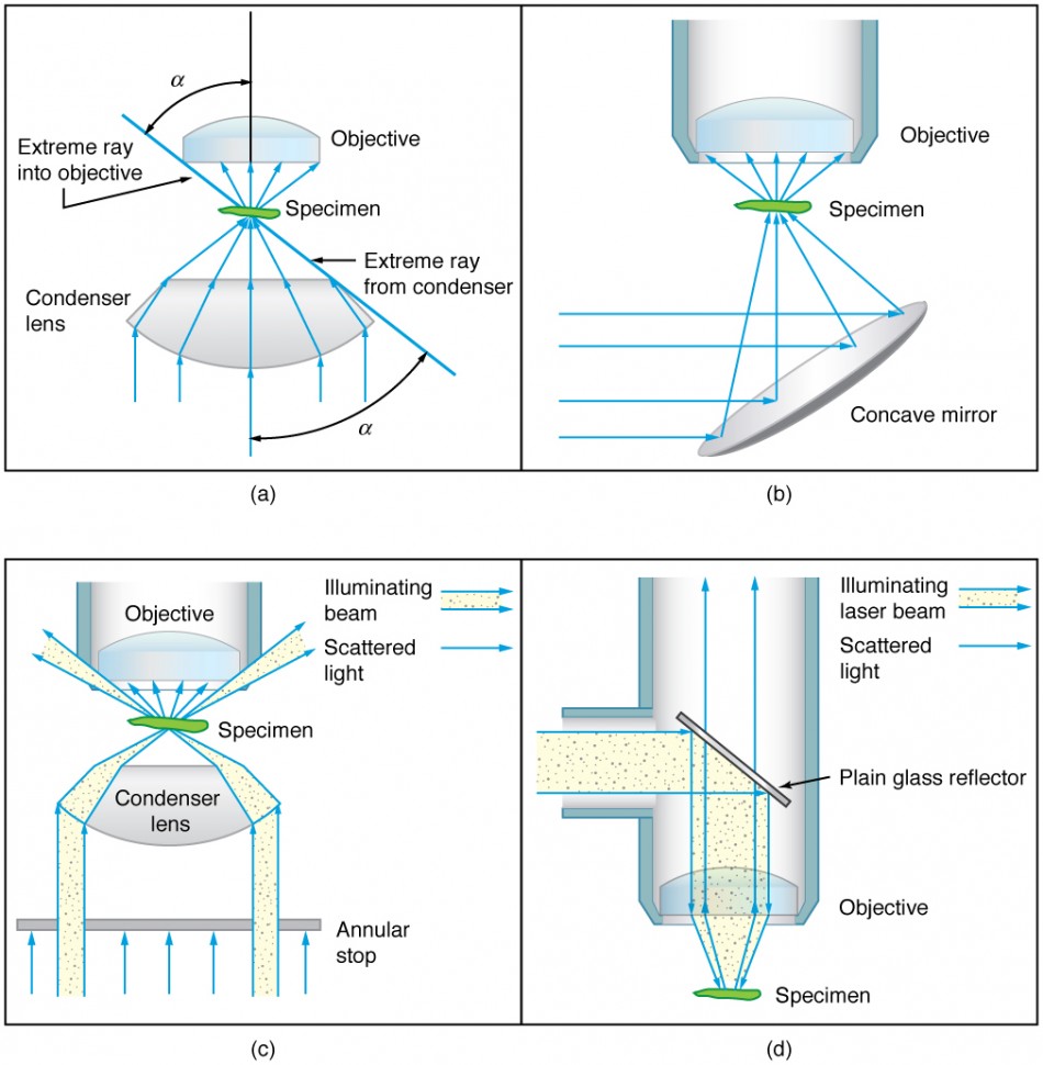
When using a microscope, we rely on gathering light to form an image. Hence most specimens need to be illuminated, particularly at higher magnifications, when observing details that are so small that they reflect only small amounts of light. To make such objects easily visible, the intensity of light falling on them needs to be increased. Special illuminating systems called condensers are used for this purpose. The type of condenser that is suitable for an application depends on how the specimen is examined, whether by transmission, scattering or reflecting. See Figure 6 for an example of each. White light sources are common and lasers are often used. Laser light illumination tends to be quite intense and it is important to ensure that the light does not result in the degradation of the specimen.
Now we must find the magnification of the eyepiece, which is given by , where di′ and do′ are the image and object distances for the eyepiece (see Figure 2). The object distance is the distance of the first image from the eyepiece. Since the first image is 186 mm to the right of the objective and the eyepiece is 230 mm to the right of the objective, the object distance is do′ = 230 mm − 186 mm = 44.0 mm. This places the first image closer to the eyepiece than its focal length, so that the eyepiece will form a case 2 image as shown in the figure. We still need to find the location of the final image di′ in order to find the magnification. This is done as before to obtain a value for :
While the numerical aperture can be used to compare resolutions of various objectives, it does not indicate how far the lens could be from the specimen. This is specified by the “working distance,” which is the distance (in mm usually) from the front lens element of the objective to the specimen, or cover glass. The higher the NA the closer the lens will be to the specimen and the more chances there are of breaking the cover slip and damaging both the specimen and the lens. The focal length of an objective lens is different than the working distance. This is because objective lenses are made of a combination of lenses and the focal length is measured from inside the barrel. The working distance is a parameter that microscopists can use more readily as it is measured from the outermost lens. The working distance decreases as the NA and magnification both increase.
Ideal for laboratory use, the Fiber-Lite MI-150 Ringlight System features 360 degrees of shadow-free, high-intensity illumination and provides the ...
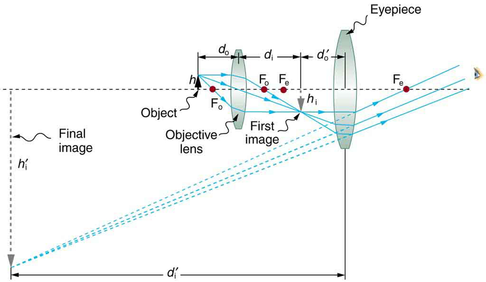
Microscopes were first developed in the early 1600s by eyeglass makers in The Netherlands and Denmark. The simplest compound microscope is constructed from two convex lenses as shown schematically in Figure 2. The first lens is called the objective lens, and has typical magnification values from 5× to 100×. In standard microscopes, the objectives are mounted such that when you switch between objectives, the sample remains in focus. Objectives arranged in this way are described as parfocal. The second, the eyepiece, also referred to as the ocular, has several lenses which slide inside a cylindrical barrel. The focusing ability is provided by the movement of both the objective lens and the eyepiece. The purpose of a microscope is to magnify small objects, and both lenses contribute to the final magnification. Additionally, the final enlarged image is produced in a location far enough from the observer to be easily viewed, since the eye cannot focus on objects or images that are too close.
Microscopes Copyright © 2021 by Lumen Learning is licensed under a Creative Commons Attribution 4.0 International License, except where otherwise noted.
To see how the microscope in Figure 2 forms an image, we consider its two lenses in succession. The object is slightly farther away from the objective lens than its focal length fo, producing a case 1 image that is larger than the object. This first image is the object for the second lens, or eyepiece. The eyepiece is intentionally located so it can further magnify the image. The eyepiece is placed so that the first image is closer to it than its focal length fe. Thus the eyepiece acts as a magnifying glass, and the final image is made even larger. The final image remains inverted, but it is farther from the observer, making it easy to view (the eye is most relaxed when viewing distant objects and normally cannot focus closer than 25 cm). Since each lens produces a magnification that multiplies the height of the image, it is apparent that the overall magnification m is the product of the individual magnifications: m = mome, where mo is the magnification of the objective and me is the magnification of the eyepiece. This equation can be generalized for any combination of thin lenses and mirrors that obey the thin lens equations.


 Ms.Cici
 8618319014500