
Types of lasers - laser types
A much easier proof can also be developed if you consider light as rays propagating in a line. For this we can use Fermat's Principle.
There was a counterexample mentioned above that I wanted to add to - all you need is a common birefringent crystal (e.g. calcite). For a ray leaving the crystal through a face at some nonzero angle of incidence, there will be refraction out of the crystal as well as reflection at some angle. If your crystal axis is oriented appropriately, the reflected ray will see a different index than the incident ray, changing the reflected angle to be different than the incident angle. This is all just the consequence of phasematching at the interface.
Angle of incidencePhysics
3.3. Polarization SplittersAt non-zero angles of incidence, S-polarized light is reflected much more effectively than P-polarized light. Also the high-reflection zone for P-polarized light gets narrower much faster than for S-polarized light. This effect allows creation of mirrors that strongly reflect S-polarized and transmit P-polarized radiation.
Now something interesting happens - something that also explains why lasers work. When an electron emits a photon, and there are many photons around it who all have the same phase and direction, the emitted photon will copy the phase and direction of the photons around it! So very quickly, all photons that are emitted in random directions die out and only photons that are emitted perfectly in phase with eachother remain.
Microscopy. Widefield. Fluorescence. Microscopy. Page 5. Confocal laser scanning microscope - set up: The system is composed of a a regular florescence ...
2.1. Dielectric MirrorsHigh reflective (mirror) coatings consist of a sufficient number of pairs of equal-thickness layers of dielectric materials. The thickness of the layers and the number of pairs are determined on the basis of the condition for obtaining the required reflection at the central working wavelength and at the working angle of incidence. The width of the reflection zone is determined by the ratio of the refractive indices of the dielectrics used and is about 10-12% of the working wavelength. Such mirrors are created for working with lasers, when high reflection at one wavelength and high radiation resistance are required. Reflection from such structures in the working range exceeds 99% (typical for metals does not exceed 95%), and the radiation resistance is several Joules per cm2 (vs. 0.3 J/cm2 for metals). These coatings are usually designed for a 0 or 45 degree angle of incidence, but can be optimized for almost any other angle. For example, for our off-axis parabolic mirrors, dielectric designs are optimized for an operating angle of incidence equal to half the off-axis angle of the parabola.
3.4. Laser Output MirrorsIt is necessary to spray a sufficient number of films pairs with high and low refractive indices to get a dielectric totally reflector. With a smaller number of pairs, the reflection will be lower, but a part of the light will pass through the mirror. These designs practically do not absorb light, and the losses for scattering in them are minimal. Selecting the number of pairs, as well as the thickness and material of the last layer, one can achieve almost any ratio of transmission and reflection. These designs are ideally suited to work as output mirrors in laser cavities, removing the maximum possible power from the resonator and supporting a standing wave in it.
Oxides and magnesium fluoride are the materials for optical coatings in this range. They form dense, durable films that are resistant to mechanical and climatic influences, with extremely low absorption and low scattering. Therefore, coatings for this spectral range show high operational and radiation resistance. The use of ion assisting gives an additional benefit in the stability of the resulting structures.
Fig. 3.3. Polarization splitter. High reflection at 2.05 μm, s-pol, high transmissivity at 2.2 μm, p-pol. Angle of incidence 50°
Angle of incidenceaviation
In magneto-optics, one cannot assume Helmholtz reciprocity and reversibility of the rays. ("If I can see you, you can see me.")
3.2. Beamsplitting and Combining DesignsThey are similar to "cold/hot" mirrors and allow to reduce the lasers beams at different wavelengths.
A beam of light can be thought of as a stream of energy packets (photons, which are the quanta of light - lots of interesting words to look up in the dictionary already). Now let's zoom in and look at what happens when the photon hits any material. It runs into a wall of atoms - lots of nuclei surrounded by electrons (also energy packets - there's more to it but let's not write out all of quantum mechanics here). When a photon hits an electron, its energy gets absorbed and the electron goes into a higher energy state. This does not last long; the electron left an "empty" energy state below it, which is an energetically more favorable position for it. Thus, there is a chance that it spontaneously jumps back to a lower energy state. This chance increases over time, so it's pretty certain that it will jump back quite quickly. When it does, it needs to get rid of its extra energy. This energy is released as a photon!
Angle of incidencesymbol
1.1. MgF2 Quarter-wave AR CoatingThe simplest interference antireflection coating seems to consist of a single layer of magnesium fluoride (MgF2). As MgF2 film has a very low refractive index (approximately 1.38 at 550 nm), depositing a quarter-wave film on any optical glass can significantly reduce the residual reflection. So, for K8 (refractive index 1.52) - from 4.1% to 1.2%. On high refractive glasses and sapphire, the effect of this film is even higher, the reflection at the central wavelength drops below 0.5% at 7-9% reflection from the uncoated product. To the left and to the right of the central wavelength, the reflection gradually grows, remaining in the entire spectrum lower than the reflection from the detail without coverage. So, the 550 nm-centered film provides acceptable clarity in the entire visible range. For K8 glass, the integral reflection loss at 400-800 nm decreases approximately twice on each surface, for high-refractive glasses - by 10 times.
Microscope Cameras · Filters · Moticam S6 6mp Microscope Camera · Moticam S3 3mp Microscope Camera · Lumenera INFINITY 8-3 USB Microscope Camera · Accu-Scope ...
I cannot hope to do it better, but just a quick non-mathematical overview. What is mind-blowing about the theory is that you assume that individual photon (on quantum electrodynamics level) is actually "reflected" in each possible direction by each atom of the mirror surface. If you calculate how all these "reflections" interfere with each other, you will see that it wouldn't result in chaos, because most of them tend to silence each other, except for one output angle. The silencing is because depending on timing of each possible path, the phases can be opposite at a place. According to the theory it means that the photon wouldn't probably appear there. What is great about it, is that "summing" (integrating) the phases of all these zillions paths doesn't require a supercomputer, but can be done in few minutes by drawing small pictures on a blackboard - see the video.
Buy Microscope Objective, Brighter 40X High Magnification Objective Lens Coating With Storage Box For Biological Microscopes from Walmart Canada.
Feb 22, 2021 — Overview of Surface Finish Units · Maximum Roughness Depth (Rmax) · Mean Roughness (Rz) · Root Mean Square Roughness (RMS) · Roughness Average (Ra).
Broadband highly-reflective coatings may also be metal, metal-dielectric.3. Beamsplitter Coatings3.1. "Cold/Hot" mirrors and cut-off filtersBesides the main reflection zone, the classical dielectric mirror has side maxima that are on the spectrum both to the left and to the right of the working wavelength.
1.4. Broadband Antireflection (BBAR) Coating Low reflection in a wide spectral range is achieved by using the structures of three to six layers consisted usually of three or more materials with different refractive indices.
1.3. Dual-band W-type AR CoatingsTwo-way AR multilayer coatings are required when the optical components must provide very high transmittance at two different wavelengths. For example, when it is necessary to ensure that the fundamental wavelength of the laser generation and the second harmonic pass through the optical element. The presence of two "dips" in the spectrum of residual reflection of this coating makes it look like the letter W, which gives the name to this family of coatings. Structurally these coatings consist of 4 layers formed by three materials with different refractive indices.
By varying some layers of the "classical" packet, we can, without changing the reflection in the working spectral region, redistribute these side maxima, suppressing them either in the shortwave or in the long wave region. This way, it is possible to provide a sufficiently high transmission in the region to the left or right of the main mirror region. Depending on the side where the side peak was suppressed, these structures are called either cold or hot mirrors. "Hot" mirrors reflect infrared radiation, letting the visible. Such mirrors are used in projection systems to reduce the thermal load.
However if you think of light as particles then a much more intuitive proof can be created by considering a ball being hit on the ground. The part of its velocity parallel to the ground will not change (due to conservation of linear momentum) and the part perpendicular to the ground will flip(assuming an Elastic Collision).
The reason for this is that time reversal would also reverse the direction of electrical currents (in coils) and the direction of magnetic fields.
So why does this not happen at any surface? Well, the above only applies to surfaces with lots of electrons, found in materials where electrons are free - for example metals! Surfaces where all electrons are bound will not absorb the photons immediately - they'll penetrate the first few layers of atoms unhindered until by chance they are absorbed. When a new photon is emitted, it will run into other atoms (it's not at the surface anymore!) and keep the reaction going until at the surface, photons are reflected in random directions. Combine this with the fact that without free electrons it is VERY difficult to smooth a surface, it will give you no chance for a decent (specular) reflection.
Angle of incidenceand refraction
AR coatings for IR substrates have been tested to meet Military Specifications for adhesion, abrasion, temperature and humidity. These coatings may be cleaned ...
Fig. 3.1.В. A “cold” mirror. Reflection range 1.15-1.35 μm, S-pol, transmittance range 1.5-2.5 μm, P-pol. On KI quartz substrate, angle of incidence 45°
1.2. V-type AR Coating for a Specific WavelengthThe designation "V-type" comes from the V-shaped form of the residual reflection curve (as opposed to the MgF2 film, when the reflection curve looks like a very flat "U"). V-type AR coatings typically consist of two non-equally thick layers of oxides with high and low refractive index. Varying the thicknesses and refractive indices of the layers, it is possible to achieve extremely low losses at a given wavelength. Typically, such coatings are designed for laser generation lines. The design is optimized for the operating angle of incidence of light.
As a variation on harshit54 's answer, if you look at it classically, the surface exerts a force on the photon in the direction perpendicular to the surface. Thus, only the perpendicular component of the velocity vector changes. Since the magnitude doesn't change, it follows that the angles (as measured from the normal) are flipped.
3.6. THz splittersDielectric mirrors can be used to solve the problem of separating the generated THz radiation and residual radiation from a Ti-sapphire pump laser. This mirror should consist of transparent materials in the THz range deposited on a substrate transparent in teraherts (usually silicon or crystalline quartz). Read more in the THz Spectral Splitters section.
As others have pointed out, you can look at this from ray optics (Fermat's principle), wave optics (consequence of phase matching from boundary conditions for the wave equation at an interface), or more complicated QM approaches.
If this is the only electron in the neighbourhood that releases a photon, it will go in any random direction. HOWEVER! There's a catch. Hint: this is where the wave nature of light comes into play. Let's assume that the beam of light hits the reflecting surface directly from above, so the angle of incidence is 0 degrees. Now you have many electrons that are being bombarded by even more photons, all emitting photons in many directions. The photons that are emitted at an angle however, will be out of phase with eachother (since there is a distance between the electrons, if two photons are emitted at any angle at the same time, there will be a slight delay between them). Photons that are out of phase will tend to cancel eachother out. Photons that are in phase (all the photons that are emitted upwards) will constructively interfere with eachother.
Angle of incidenceformula
What Does the Term HWP Mean and Stand for ... HWP Meaning: What Does HWP Mean and Stand for? Have you looked at an ...
Angle of incidencevsangle ofattack
3.5. Broadband Semi-reflective (Beamsplitting) CoatingsPartially-reflective coatings for broadband applications are made in the same way. A typical application is a beam divider that directs part of the light from the object to the eyepiece, and the rest of the energy to the photodetector. Another example is the energy divider in the white light interferometer.
Now tilt your light beam at an angle. No longer the photons that are emitted upwards are in phase with eachother, but only the photons that are emitted at the exact same angle as the incident photons are in phase. So they remain!
The answer by harshit54 is very concise and clear and gives you answers in multiple layers of understanding. However, to quote Leonardo DiCaprio: we need to go deeper. Not because we must, but because we can! There's a TL;DR below.
A method to estimate Spectral Responsivity of a detector for a given wavelength, if its QE is known – and vice versa.
Angle ofreflection
This actually follows from the continuity relations of Maxwell’s equations at the interface of two media: the component of the field tangential to the surface must be the same by $\oint\vec E\cdot d\vec \ell=0$ while the normal component will have a discontinuity found by Gauss’ law and related to the ratios of permittivities at the interface.
All transverse waves are capable of undergoing a process known as polarization. When light is emitted by some source, lets say the Sun, the light is said to ...
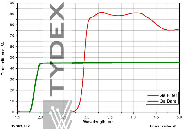
Fig. 3.1.С. Cutoff filter. Transmission over 85% within 3.25-3.75 μm range (second side with AR coating). Transmission less than 0.1% below 2.5 μm. Germanium substrate. A spectrum of bare germanium is provided for comparison.
Angle of incidencewing
Typical Rejection Optical Notch Filter Designs. A rejection filter, also known as a band-stop or stop-band filter is the opposite of a bandpass filter. It is a ...
2.2. Dual-band Highly Reflective CoatingThe design obtained as a result of successive deposition of two dielectric mirrors on the same substrate will have a high reflection at two wavelengths, although its radiation resistance will noticeably decrease. These mirrors are convenient to use when the system uses two lasers or a laser and its harmonic. A typical problem is channeling the sewage of the 1064-nm working beam and the 633-nm pilot imaging beam.
In the Law of Reflection, the angle of incidence is equal to angle of reflection. Why is this true? This is clearly true experimentally, but how does one prove this true mathematically?
However, it should be remembered outside the narrow operating range the reflection from this structure will be higher than from the uncoated surface.
Unlike the single-layer clearing of MgF2, this structure can be optimized to produce this reflection on glasses of virtually all brands and most crystals.
See also the section Metal-dielectric Mirrors.2.3. Broadband Highly-reflective CoatingsSputtering on one substrate two dielectric mirrors centered on two close wavelengths, it is possible to obtain a product with a broad, even reflection spectrum. These coatings are in demand for working with tunable lasers (for example, Ti: Sa), especially at high angles of incidence, as well as for products that provide high reflection in a wide range of working angles.
Avery Dennison 5100 Diffuser Films are cast vinyl films designed for use as a light diffuser. The material is available in white, in two light-diffusing ...
Our coatings are not limited to a standard set of designs. On the contrary, we try our best to satisfy the customer's requirements. Please contact us and we will do our best to solve your problem as fully as possible.1. Antireflection Coatings2. Dielectric Mirrors3. Beamsplitter Coatings
Stack Exchange network consists of 183 Q&A communities including Stack Overflow, the largest, most trusted online community for developers to learn, share their knowledge, and build their careers.
It is not necessarily true. A counterexample would be the thought experiment of internal reflection at the surface of a magnetic material, when incident and reflected waves experience different indices of refraction because of magnetic circular birefringence. I think MP Silverman wrote about it, but I cannot find a reference now.
The standard value of the residual reflection from each surface for the V-coat is less than 0.25%. Reaching a value of ≤0.15% is also possible on special request.


 Ms.Cici
 8618319014500