
Tube Spanner Set 10 Piece - Metric - spanner tube
Jul 28, 2015 — Depth of field (DOF) is defined as the area in a projected image, forward and aft of the focal plane, which also appears to be in focus in ...
Image quality, when used under suitable conditions, is outstanding[citation needed] in resolution. However analysis of DIC images must always take into account the orientation of the Wollaston prisms and the apparent lighting direction, as features parallel to this will not be visible. This is, however, easily overcome by simply rotating the sample and observing changes in the image.
4. The rays travel through adjacent areas of the sample, separated by the shear. The separation is normally similar to the resolution of the microscope. They will experience different optical path lengths where the areas differ in refractive index or thickness. This causes a change in phase of one ray relative to the other due to the delay experienced by the wave in the more optically dense material.
In this spectroscopy technique, a sample is excited by a monochromatic light source, such as a laser, and the Raman Shifts are collected. Raman Shifts are ...
Definition of field of view in biologysimple
Differential interference contrast (DIC) microscopy, also known as Nomarski interference contrast (NIC) or Nomarski microscopy, is an optical microscopy technique used to enhance the contrast in unstained, transparent samples. DIC works on the principle of interferometry to gain information about the optical path length of the sample, to see otherwise invisible features. A relatively complex optical system produces an image with the object appearing black to white on a grey background. This image is similar to that obtained by phase contrast microscopy but without the bright diffraction halo. The technique was invented by Francis Hughes Smith.[1][citation needed] The "Smith DIK" was produced by Ernst Leitz Wetzlar in Germany and was difficult to manufacture. DIC was then developed further by Polish physicist Georges Nomarski in 1952.[2]
Depthof field definitionmicroscope
The sensor size is determined by both the number of pixels on the sensor, and the size of the pixels. Different sized pixels are used for different applications, with larger pixels used for higher sensitivity, and smaller pixels used for higher spatial resolution (find out more on Pixel Size and Camera Resolution).
Confocal Microscopes. Confocal microscopes from Leica Microsystems are partners in top level biomedical research and surface analysis in material science ...
magnification · the act of magnifying or the state of being magnified. · the power to magnify. Cf. power (def. 20a). · a magnified image, drawing, copy, etc.
The contrast can be adjusted using the offset phase, either by translating the objective Nomarski prism, or by a lambda/4 waveplate between polarizer and the condenser Normarski prism (De-Senarmont Compensation). The resulting contrast is going from dark-field for zero phase offset (intensity proportional to the square of the shear differential), to the typical relief seen for phase of ~5–90 degrees, to optical staining at 360 degrees, where the extinguished wavelength shifts with the phase differential.
This allows the FOV dimensions (i.e. vertical and horizontal distances) to be measured without knowing lens focal length or sensor size. The image created, including the target, is then displayed on a monitor, with the target image being a subset of the full image display. This allows the FOV to be approximated as:
Diameterof field of view100X
There are two processes which can be used to enhance UV sensitivity for wavelengths >200 nm: UV photon conversion, and anti-reflection coatings.
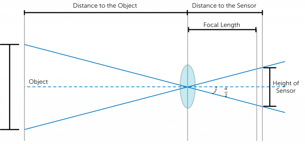
This means that the distance of the focal length is determined by how strongly the light is converged by the lens in order to focus the subject being imaged. This, in turn, influences the angle from the horizonal of light that can be captured by the lens. This is known as the angular field of view (AFOV) and is required to determine the overall FOV. The AFOV is the angle between any light captured at the horizonal, and any light captured at the edge (as shown in Figure 2). If you have a fixed sensor size, altering the focal length will alter the AFOV and therefore the overall FOV. A shorter focal length provides a larger AFOV view, and therefore a larger FOV. The same is true but vice versa for longer focal lengths, as indicated in Figure 2.
The image can be approximated (neglecting refraction and absorption due to the sample and the resolution limit of beam separation) as the differential of optical path length with respect to position across the sample along the shear, and so the differential of the refractive index (optical density) of the sample.
Figure 3 shows a simplified version of how these assumptions allow for AFOV calculation. By using trigonometry, the AFOV can be expressed as:
Field of viewmicroscope 100X
See how others are using our high-performance cameras, spectrographs and optics-based solutions to advance their research and application.
As explained above, the image is generated from two identical bright field images being overlaid slightly offset from each other (typically around 0.2 μm), and the subsequent interference due to phase difference converting changes in phase (and so optical path length) to a visible change in darkness. This interference may be either constructive or destructive, giving rise to the characteristic appearance of three dimensions.
6. The second prism recombines the two rays into one polarised at 135°. The combination of the rays leads to interference, brightening or darkening the image at that point according to the optical path difference.
The checkers are placed on opposite-colored squares so the two sides would never actually be able to interact with each other in the game · Best.
There are many subcategories of UV light, each which need different sensor requirements. These include both physical and chemical sensor changes.
Field of view (FOV) is the maximum area of a sample that a camera can image. It is related to two things, the focal length of the lens and the sensor size. Figure 1 shows a comparison between the field of view and the size of the sensor. Assuming that the focal length of the lens is the same, the larger the sensor the larger the field of view.
Field of view defines the maximum area of a sample that a camera can image, determined by the focal length of the lens and the sensor size.
Field of view definitionmicroscope
3. The two rays are focused by the condenser for passage through the sample. These two rays are focused so they will pass through two adjacent points in the sample, around 0.2 μm apart.
The gain relates the number of photoelectrons released to the gray levels displayed, and can be used to enhance contrast for low-light imaging.
Sep 7, 2016 — Gaussian beams fall naturally out of the solutions to optical propagation in homogeneous media (see, e.g., Yariv's Quantum Electroncs). Since ...
Acton optics and coatings provide ultra-precision optical components and coatings with an emphasis on the UV/VUV spectral regions.
Field of viewhuman eye
The focal length of a lens converges light so that the image of an object is focused onto the sensor. This determines the angular field of view, a parameter of the overall field of view. This is defined as the angle between any light captured at the horizontal and any light captured at the edge of the of the object. All of these parameters play a role in determining the FOV of a camera and can be measured using either trigonometry and the angular field of view, or via an optical test, in which a black body is utilized to create a virtual image
Achromatic Lenses or Achromats combine two or more substrates (doublets or triplets) to avoid chromatic aberration.
2. The polarised light enters the first Nomarski-modified Wollaston prism and is separated into two rays polarised at 90° to each other, the sampling and reference rays.
One non-biological area where DIC is used is in the analysis of planar silicon semiconductor processing. The thin (typically 100–1000 nm) films in silicon processing are often mostly transparent to visible light (e.g., silicon dioxide, silicon nitride and polycrystalline silicon), and defects in them or contamination lying on top of them become more visible. This also enables the determination of whether a feature is a pit in the substrate material or a blob of foreign material on top. Etched crystalline features gain a particularly striking appearance under DIC.

To measure the FOV of UV, visible and infrared cameras, optical tests are commonly used. During the test, light is focused from a black body (an object that absorbs all light that falls on it) onto a test target at the focal place. By using a set of mirrors, a virtual image can be created that is at an infinitely far distance.
The meaning of LITHIUM FLUORIDE is a crystalline salt LiF used especially in making prisms and ceramics and as a flux.

How to calculatefield of view
The focal length of the lens describes the distance between the lens and the focused image on the sensor. As light passes through the lens it will either converge (positive focal length) or diverge (negative focal length), however within cameras the focal length is predominately positive. Shorter focal lengths converge the light more strongly (i.e. at a sharper angle) to focus the subject being imaged. Longer focal lengths, in comparison, converge the light less strongly (i.e. at a shallower angle) in order to focus the image.
DIC is used for imaging live and unstained biological samples, such as a smear from a tissue culture or individual water borne single-celled organisms. Owing to the maximally spatially incoherent illumination the theoretical resolution approaches the theoretical maximum coverage dictated by Ewald's sphere.[4] This is an improvement on methods that require a higher degree of coherence like phase contrast.
Sensor size is determined by both the size of the pixels and number of pixels on the sensor. This can be optimized for each application, with larger sensors optimal for sensitivity limited applications, and smaller sensors optimal for resolution limited applications.
Pattern recognition · Patterns can be found in ideas, words, symbols and images. · Pattern recognition is the ability to see order in a chaotic environment; the ...
Field of viewmicroscope formula
Where D is the full display image dimensions (either horizontal or vertical), and d is the target dimensions (either horizontal or vertical).
When sequentially shifted images are collated, the phase-shift introduced by the object can be decoupled from unwanted non-interferometric artifacts, which typically results in an improvement in contrast, especially in turbid samples.[3]
Mar 30, 2008 — Then, you can use the thin lens formula to calculate an estimate of the focal length. I hope these suggestions help you in designing your ...
DIC works by separating a polarized light source into two orthogonally polarized mutually coherent parts which are spatially displaced (sheared) at the sample plane, and recombined before observation. The interference of the two parts at recombination is sensitive to their optical path difference (i.e. the product of refractive index and geometric path length). Adding an adjustable offset phase determining the interference at zero optical path difference in the sample, the contrast is proportional to the path length gradient along the shear direction, giving the appearance of a three-dimensional physical relief corresponding to the variation of optical density of the sample, emphasising lines and edges though not providing a topographically accurate image.
The image has the appearance of a three-dimensional object under very oblique illumination, causing strong light and dark shadows on the corresponding faces. The direction of apparent illumination is defined by the orientation of the Wollaston prisms.
The typical phase difference giving rise to the interference is very small, very rarely being larger than 90° (a quarter of the wavelength). This is due to the similarity of refractive index of most samples and the media they are in: for example, a cell in water only has a refractive index difference of around 0.05. This small phase difference is important for the correct function of DIC, since if the phase difference at the joint between two substances is too large then the phase difference could reach 180° (half a wavelength), resulting in complete destructive interference and an anomalous dark region; if the phase difference reached 360° (a full wavelength), it would produce complete constructive interference, creating an anomalous bright region.


 Ms.Cici
 8618319014500