
The Science Behind Anti-Reflective Coating - how does an anti reflective coating work
Apr 16, 2018 — "A thin lens of focal length f is used to collimate the light emerging from an optical fibre. The fibre has small core diameter and numerical ...
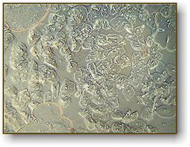
Image above with regular brightfield objectives. Notice the air bubbles at three locations, some cells are visible on the left.
Next, you will need to remove one of the eyepiece lenses and insert the centering telescope in its place. The set screw is used to focus the centering telescope. When looking through the telescope, you will see two rings. They may or may not be concentric. By turning the centering adjustment screws on the condenser, you align the rings so that they are concentric (see the images below). Finally, remove the centering telescope and replace the eyepiece lens. Put your specimen back on the stage and you are ready for phase observations. When you change objectives, you should go through this centering procedure again (although you may discover that the alignment remains consistent with all objectives).
In order to set up your microscope to view objects with phase contrast you must have phase contrast objective lenses and a phase contrast substage condenser.
3-Space Foldable Multi Guitar Rack · Keep all your guitars together. Have them ready no matter where the music takes you. · Holds 2 acoustics + 1 electric, or ...
For a multimode semiconductor laser with Δλ = 2 nm and a dispersion-shifted fiber with S = 0.05 ps/(km-nm2) at λ = 1.55 μm, the BL product can approach 5 (Tb/s)-km. Further improvement is possible only by using single-mode semiconductor lasers.
where subscripts x and y stand for the direction of linear polarization, and previous equation was used to relate the group velocity vg to the propagation constant β. Similar to the case of intermodal dispersion discussed for multimode fibers, the quantity ΔT/L is called polarization dispersion. Its values for conventional single-mode fibers are typically below 0.1 ps/km and are negligible compared to GVD. Such low values result from a coupling between the two modes induced by random perturbations along the fiber. The coupling tends to equalize the propagation time for the two polarization components. For polarization-preserving fibers ΔT/L can be quite large ( ~ 1 ns/km) if the two components are equally excited at the fiber input but can be reduced to zero by launching light along one of the principle axes. Most lightwave systems currently use conventional (nonpolarization-perserving) fibers. Polarization dispersion is not a practical limitation for such fibers until the effects of GVD become negligible.
The main effect of waveguide dispersion is to shift λZD by an amount 30-40 nm so that the total dispersion is zero near 1.31 μm. It also reduces D from its material value DM in the wavelength range 1.3-1.6 μm that is of interest for optical communication systems. Typical values of D are in the range of 15-18 ps/(km-nm) near 1.55 μm. This wavelength region is of considerable interest for lightwave systems since the fiber loss is minimum near 1.55 μm. High values of D can limit the performance of 1.55-μm lightwave systems.
The parameter β2 = d2β/dω2 is known as the GVD parameter. It determines how much an impulse would broaden on propagation inside the fiber.
We offer several different microscopes that include phase contrast. They are listed below, with the highest quality found in the Meiji microscope.
Figure 1: Diagram of the directions of propagation and displacement for three types of wave: (a) longitudinal, (b) transverse (unpolarised), and (c) transverse ...
where ωj is the resonance frequency and Bj is the oscillator strength. Here n stands for n1 or n2 depending on whether the disperse properties of the core or the cladding are considered.
In optical communication systems the frequency spread Δω is often determined by the range of wavelengths Δλ emitted by the optical source. It is customary to use Δλ in place of Δω. By using ω = 2πc/λ and Δω = (-2πc/λ2)Δλ, we can rewrite the equation as
The Webcam Resolution Test is a simple and free method to check online, what is the resolution of your webcam. As a result of testing, you will get the complete ...
Shown at the left is the phase contrast kit used with National Optical model 160 series of microscopes. The kit consists of 4 objective lenses, a centering telescope and a Zernike phase condenser lens. The long silver adjustment screws on either side of the condenser lens push in to engage set screws inside the condenser for proper alignment.
This is a simulation of a typical laser diffraction lab set up. Examine the set up in the 3D window, it shows a laser, a diffraction grating, and a screen. Use ...
The contribution of waveguide dispersion DW to the dispersion parameter D is given in the previous equations and depends on the V parameter of the fiber. The following figure shows how d(Vb)/dV and Vd2(Vb)/dV2 change change with V. Since both derivatives are positive, DW is negative in the entire wavelength range 0-1.6 μm.
The sum in the equation extends over all material resonances that contribute in the frequency range of interest. In the case of optical fibers the parameters Bj and ωj are obtained empirically by fitting the measured dispersion curves to this equation with M = 3. They depend on the amount of dopants and have been tabulated for several kinds of fibers. For pure silica these parameters are found to be B1 = 0.6961663, B2 = 0.4079426, B3 = 0.8974794, λ1 = 0.0684043 μm, λ2 = 0.1162414 μm, and λ3 = 9.896161 μm, where λj = 2πc/ωj (j = 1, 2, and 3). The group index ng = n + ω(dn/dω) can be obtained by using these parameter values.
The dispersion parameter D can vary considerably when the operating wavelength is shifted from 1.3 μm, near which it takes the minimum value. The wavelength dependence of D is governed by the frequency dependence of the mode index , D can be written as
Consider a single-mode fiber of length L. A specific spectral component at the frequency ω would arrive at the output end of the fiber after a time delay T = L/vg, where vg is the group velocity defined as
Oct 22, 2024 — LST calculator: A program for retrieving Land Surface Temperature from Landsat TM/ETM+ imagery. March 2013; Environmental Engineering and ...
Our precision polished bi-concave lenses are great for beam expansion applications and are offered with high quality anti-reflection coatings.
OWTTWO 20th Anniversary Wedding Gift,20th Anniversary Ornament for Couple,Parents,Husband,Wife,Him,Her · H · Harshita ; Premium Vector | 20th years anniversary ...
Here n2g is the group index of the cladding material and the parameter V and b are given previously. Δ was assumed to be frequency independent. A third term known as differential material dispersion can be added when dΔ/dω ≠ 0. Its contribution is, however, negligible in most cases of practical interest.
We have seen that intermodal dispersion in multimode fibers leads to considerable broadening of short optical pulses (- 10 ns/km). In the geometrical-optics description such a broadening was attributed to different paths followed by different rays. In the modal description it is related to the different mode indices (or group velocities) associated with different modes.
The above figure shows the wavelength dependence of n and ng in the range 0.5-1.6 μm for fused silica. Material dispersion DM is related to the slope of ng by the relation DM = c-1(dng/dλ). It turns out that dng/dλ = 0 at λ = 1.276 μm. This wavelength is referred to as the zero-dispersion wavelength λZD, since DM = 0 at λ = λZD. The dispersion parameter DM is negative below λZD and becomes positive above that. In the wavelength range 1.25-1.66 μm it can be approximated by an empirical relation
The main advantage of single-mode fibers is that intermodal dispersion is absent simply because the energy of the injected pulse is transported by a single mode. However, pulse broadening does not disappear altogether. The group velocity associated with the fundamental mode is frequency dependent because of chromatic dispersion. As a result, different spectral components of the pulse travel at slightly different group velocities, a phenomenon referred to as group-velocity dispersion (GVD), intramodal dispersion, or simply fiber dispersion.
Phase contrast is a method developed in the early 20th century by Frits Zernike. Zernike discovered that if you can speed up the direct light path, you can cause destructive interference patterns in the viewed image. These patterns create details in the image to appear darker against a light background. To cause these interference patterns, Zernike developed a system of rings located both in the objective lens and in the condenser system. When aligned properly, light waves emitted from the illuminator arrive at your eye 1/2 wavelength out of phase. The image of the specimen then becomes greatly enhanced. Phase is only useful on specimens that do not absorb light (they are called "phase objects") and it is very useful in showing details in certain specimens such as cell parts in protozoans, bacteria, sperm tails and other types of unstained cells. This technique proved to be such an advancement in microscopy that Zernike was awarded the Nobel prize in physics in 1953. You can see the Frits Zernike biography here.
The effect of dispersion on the bit rate B can be estimated by using the criterion BΔT < 1 in a manner similar to that used previously. By using ΔT from last equation this condition becomes
A possible source of pulse broadening is related to fiber birefringence. As discussed previously, small departures from perfect cylindrical symmetry lead to birefringence because of different mode indices associated with the orthogonally polarized components of the fundamental fiber mode. If the input pulse excites both polarization components, it becomes broader at the fiber output as the two components disperse along the fiber because of their different group velocities. This phenomenon is referred to as polarization dispersion. The time delay ΔT for a fiber of length L is given by
This equation provides an order-of-magnitude estimate of the bit rate-distance product BL offered by single-mode fibers. In the next two sections the wavelength dependence of D is studied. It is found that D ~ 1 ps/(km-nm) can be obtained in the wavelength region near 1.3 μm. For a semiconductor laser the spectral width Δλ is 2-4 nm even when the laser operates in several longitudinal modes. The BL product of such lightwave systems can exceed 100 (Gb/s)-km. Indeed, a second-generation commercial telecommunication system in 1987 was capable of operating 1.7 Gb/s with a repeater spacing of 40-50 km, demonstrating the potential of single-mode fibers for optical communications. The BL product of single-mode fibers should be compared with multimode step-index fibers for which BL < 100 (Mb/s)-km because of intermodal dispersion.
Material dispersion occurs because the refractive index of silica, the material used for fiber fabrication, changes with the optical frequency ω. On a fundamental level, the origin of material dispersion is related to the characteristic resonance frequencies at which the material absorbs the electromagnetic radiation through oscillations of bound electrons. Far from the medium resonances, the refractive index n(ω) is well approximated by the Sellmeier equation
At λ = λZD, β2 = 0, and S is proportional to β3. Typical value of S at λ = λZD are 0.085 ps/(km-nm2) for standard single-mode fibers and 0.05 ps/(km-nm2) for dispersion-shifted fibers with λZD = 1.55 μm. For a source of spectral width Δλ, the effective value of dispersion parameter becomes D = SΔλ. The limiting bit rate-distance product can be estimated by using previous equation with this value of D or by using
OBJECTIVE LENS meaning: a lens or system of lenses in a microscope, telescope, etc., that forms an image of an object.
Not all phase contrast microscopes are the same but generally they rely on similar techniques to set up the system for optimum results. In the system shown at the right, the phase condenser has five settings that you can rotate through (10x, 20x, 40x, 100x and BF) BF is "brightfield" with no phase. To set up your microscope for phase optics, you first set it at BF and focus on the specimen. Adjust the height of the condenser for optimum image quality. Next, set the condenser turret to the phase setting for that particular lens and remove the specimen. The controls that stick out from both sides on the back are for centering the condenser.
The frequency dependence of the group velocity (or GVD) leads to pulse broadening simply because different spectral components disperse during propagation and become desynchronized at the fiber output. If Δω is the spectral width of the pulse, the extent of the pulse broadening is governed by
It should be stressed that λZD = 1.276 μm only for pure silica. It can vary in the range 1.27-1.29 μm for optical fibers whose core and cladding are doped to vary the refractive index. The zero-dispersion wavelength of optical fibers also depends on the core radius a and the index step Δ through the waveguide contribution to the total dispersion. This issue is discussed in the following section.
On the other hand, DM is negative for wavelengths below λZD and becomes positive above that. The following figure shows DM, DW, and their sum, D = DM + DW, for a typical single-mode fiber.
The Villain Weapon Systems GL4 External Focusing Lens addresses the wide flood pattern of the GL4's IR illuminator and focuses the 300mW beam into a tight ...
Since the waveguide contribution DW depends on the fiber parameters such as the core radius a and the index difference Δ, it is possible to design the fiber such that λZD is shifted in the vicinity of 1.55 μm. Such fibers are called dispersion-shifted fibers. It is also possible to tailor the waveguide contribution such that the total dispersion D is relative small over a wide wavelength range extending from 1.3 to 1.6 μm. Such fibers are called dispersion-flattened fibers. The following figure shows typical examples of the wavelength dependence of D for standard (conventional), dispersion-shifted, and dispersion-flattened fibers. The design of dispersion-modified fibers involves the use of multiple cladding layers and a tailoring of the refractive-index profile. Design issues are discussed in another tutorial.
A common activity in high school biology is to observe cheek cells. To do this, one takes a flat toothpick and gently scrapes the inside of their cheek. They smear the specimen on a flat microscope slide and cover it with a cover slip. The cheek cells are epithelial cells and will be seen in large numbers. If you add a drop of iodine to the sample, the nuclei of the cells will become more visible. They will appear as small round dots inside the cell. In the picture on the left, we see the cells as they would appear without iodine with a regular microscope. At the right, you see the same specimen using a phase contrast microscope (actually, we used the same microscope with different lenses). This clearly shows that, for some specimens, phase contrast will greatly improve your image quality.
Intramodal dispersion has two contributions known as material dispersion and waveguide dispersion. This tutorial considers both of them and discusses how GVD limits the performance of lightwave systems employing single-mode fibers.
It appears that the BL product of a single-mode fiber can be increased indefinitely by operating at the zero-dispersion wavelength λZD where D = 0. The dispersive effects, however, do not disappear completely at λ = λZD. Optical pulses still experience broadening because of higher-order dispersive effects. This can be understood by noting that D cannot be made zero at all wavelengths contained within the pulse spectrum centered at λZD. Clearly, the wavelength dependence of D will play a role in pulse broadening. The higher-order dispersion is thus governed by the "dispersion slope" S = dD/dλ. The parameter S is also called differential-dispersion parameter or second-order dispersion parameter. It can be written as


 Ms.Cici
 8618319014500