
Flange Focal Distance of Photographic Lenses and Cameras - flange focal length
To study the in-band emission, we place calibrated, EUV-sensitive photodiodes at angles 30°, 41°, 64°, 90°, and 114 ° with respect to the laser axis as shown in Fig. 1(a). The combined measurement of the EUV photodiodes results in the anisotropy corrected absolute total emission of EUV light. The conversion efficiency of laser light energy into 13.5 nm light emitted in the hemisphere toward the laser is calculated accordingly. The uncertainty in the CE value is calculated considering the uncertainties in the laser energy measurement (2%), calibrating the EUV photodiodes (6%), and the anisotropic fit used to extract the emission fraction into 2π (9% systematic uncertainty), as well as accounting for statistical errors. We study emission spectra in the range 5.5–25 nm using a transmission grating spectrometer, which we orient at 60° (cf. Bouza et al.29). We additionally investigate the source emission area by acquiring images of the 13.5 ± 1 % nm emission using a concave multilayer Mo/Si mirror in combination with an EUV-sensitive CCD (Greateyes BI UV1). This EUV imaging system is placed at 90°. Data presented are averages of 100–200 laser shots.
It can be used to look at blood cells and parts of a cell, tissue sections, yeast, bacteria, algae, various kinds of invertebrates, protists and metazoans, pond water, soil infusions, hay, precious stones such as diamonds, and fractures on metals.
Illustration showing how to measure the focal length of a converging lens using a distant object. Diverging (or Concave) lenses.
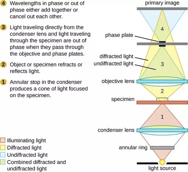
Phase contrastmicroscope definition
We all know about the basic facets of light microscopy, especially that of bright field microscopy, since it’s what we always encounter. But, there are lots of other types of microscopy techniques that are just as simple, but work so much better.
In order to fully understand what dark field microscopy is and how it works, it’s important to first understand the basic principles of bright field microscopy, since dark field is a derivative of this elementary microscopy technique.
The great thing about dark field microscopy is that it’s fundamentally simple yet highly effective. It offers a high contrast and high-resolution image, which is especially beneficial for live and unstained biological samples.
We would like to thank Iliya Cerjak and Henk-Jan Boluijt for their work in designing the experimental setup and Laurens van Buuren for the aid in assembling the setup and its operation. We would like to further thank Ruben Schupp and Muharrem Bayraktar for their help with the experimental work as well as Lucas Poirier and Michael Purvis for helpful discussions. This research was funded by the European Research Council (ERC StG 802648) and the Dutch Research Council (Vidi 15697 and OTP 19458).
This works by mapping the intensity of the electron beams diffracted from the specimen in relation to the projected position of this specimen. As a result, when it comes to crystals, its reflective capability becomes pronounced, or lattice defects and bending are identified.
Scaling of EUV source size (measured at 90°) with laser diameter and intensity. (a) Image of the EUV emission area for a maximum CE = 5.0% case. The laser propagates along the +ẑ direction. (b) Image of the EUV emission area for high in-band emission (12.2 mJ). (c) Plasma source size ØEUV as calculated by its full width at 20% of the maximum intensity along the r̂ () and ẑ () directions as a function of laser spot size ØL. All data points are acquired at a laser intensity of 0.7 ×10¹¹ W/cm2. The gray dashed line indicates a trendline fit to the data. Data entries corresponding to the images in panels (a) and (b) are indicated. (d) Source size of a 67 μm laser beam with different intensities in the range 0.3–2 ×10¹¹ W/cm2. Inset of (d) shows the scaling of source size with pulse duration in the range 10–23 ns. All the above-mentioned source sizes enclose ≥ 75% of the EUV emission energy.
Another type of light microscope that can be turned into a dark field microscope is a dissecting microscope. What needs to be done here is to place a flat black cover on the specimen stage to cover the opening and serve as the specimen’s background.
Advantages and disadvantagesof dark field microscope
In this work, we present the high-efficiency operation of 2 μm laser-produced plasmas, achieving up to CE = 5% using a simple two-pulse scheme. We demonstrate that the optimization of the laser's temporal and spatial profiles, as enabled by our recent laser development,27 allows for future, high-performance EUV sources powered by 2 μm laser technology. Scaling to high (up to 12.5 mJ) EUV pulse energies is demonstrated while maintaining a small emission size.
(a) Overview of the experimental setup showing 2 μm main-pulse impacting preformed tin targets. Five diodes are placed at angles 30°, 41°, 64°, 90°, and 114° with respect to the laser axis. EUV spectra are measured using a transmission grating spectrometer positioned at 60°. EUV emission profiles are imaged using a concave multi-layer mirror imaging system at 90°. For three different main-pulse diameter cases of 67 μm flat-top (), 144 μm flat-top (), and 120 μm Gaussian (), we show (b) the laser temporal profiles where a shorter pulse duration of 67 μm flat-top () case is also presented, and (c) angularly averaged laser radial profiles and (d)–(f) showing the respective spatial intensity profiles.
In conclusion, we have demonstrated highly efficient in-band EUV production from 2 μm-laser-generated plasma, obtaining a peak 5% conversion efficiency competitive with the industrial CO2-gas-laser powered state-of-the-art. Combined with the benefits of solid-state laser technology currently under development, in particular, with its promise of much larger (up to ∼20%, see Refs. 21 and 36) wall-plug efficiency, and laser pulse energy and power scalability,15,36 our findings make 2 μm-LPP a particularly promising candidate to power future EUV nanolithography machines. We further show the possibility to scale the extreme ultraviolet light emission toward high energies by studying output in-band energy scaling with laser spot size, intensity, and pulse duration. High in-band EUV energies of up to 12.5 mJ have been achieved, with scope for further scaling, while maintaining small emission source sizes match typical etendues of the EUV optics column. Further studies are required to optimize tin-target delivery, minimizing “debris” generation,10,37 including investigating the potential of further simplifying the plasma formation process.
The best type of light microscope to modify into a dark field microscope is the compound light microscope, since the basic mechanism is already there, and is just missing a couple of key components.
This is great for opaque, transparent, and low contrast specimens, especially if staining is not a viable option. Here is the exact imaging process of a typical dark field microscope:
Dark fieldmicroscopy
That said, it still works best when the necessary components are built into the microscope, especially the patch stop or occulting disk. In any case, what’s important to remember is that dark field microscopy requires intense lighting, so mirrored microscopes will not be suitable.
The exact process starts as a patch stop (or sometimes a wide phase annulus) blocks most of the incoming light, only leaving an outer ring of light to enter the condenser. This light is then focused and transmitted through the specimen, with a small percentage becoming scattered.
Embark on a journey of illumination with the Portaleon SGE1011 Hexagon LED Tunnel Light. This state-of-the-art lighting solution introduces a dimension of ...
Having said all of these things, dark field microscopy does come with a few limitations, the most important one being that the samples are at more risk of being damaged due to exposure to intense lighting.
Advantagesof dark field microscope
In dark field microscopy, the specimen is lit by a hollow yet focused cone of light that is controlled by the condenser. The objective lens rests just outside this bright area, and this light travels around the lens without actually entering the cone set by the condenser.
The images produced through dark field microscopy are also somewhat more difficult to interpret and analyze, especially if you are much more used to bright field microscopy techniques.
We observe an increasing CE for increasing target diameters for three main-pulse cases as shown in Fig. 2(a). The dashed lines are based on a CE scaling with the geometrical overlap of the main-pulse laser spatial profile [taken from Fig. 1(c)] with the tin target for the three cases, with the amplitude as a free fit parameter following the approach of Schupp et al.18 We offset the geometrical overlap function along the x-axis by a common 21 μm [number taken from Fig. 4(c), consistent with simulations13] to account for plasma expansion, which enlarges the area where the beam is absorbed13,17 for pulse durations beyond several nanoseconds.18,30 These simple model curves closely match the experimental data. For the flat-top cases, the CE plateaus but at target diameters larger than the beam, as may be expected given that part of the laser energy is situated outside of the area set by the flat-top diameter. Figure 2(a) shows that flat-top pulses result in higher conversion efficiencies than the Gaussian one. This difference is attributed to the uniform heating of the LPP, resulting in a uniform temperature and emission within the 13.5 nm band across the plasma. Non-uniform illumination may overheat and underheat areas of the plasma, resulting in unwanted out-of-band emission.31 Underheated plasma regions may, moreover, lead to additional self-absorption.16,31,32 We note that there is no difference in the maximum obtained CE comparing the 67 and 144 μm flat-top cases. Schupp et al.26 found that enlarging beam size negatively impacted CE when using 1 μm drive laser pulse due to increasing optical depth, in contrast with the current findings. This contrast is indicative of the lower plasma densities, and optical depth, of the 2 μm case leading to less self-absorption of the produced EUV light.16
All presented source sizes match typically reported etendues.10,14 For example, an etendue of 3.3 mm 2 sr (number taken from Refs. 10 and 11) for a collector covering 5.5 sr of the forward hemisphere10,11 may be efficiently matched to a source size below approximately 6002 μm2, assuming isotropic hemispherical emission. Of course, this view represents a strong simplification of the complex beam transport through the optical column through which EUV light is guided onto the wafer.
You can also see the movement of live specimens such as that of bacteria and organisms in water samples. And, dark field microscopy makes it easy to perform quality checks on a variety of stones and metals, since it easily highlights faults, cracks, and fractures.
Instead, use an external high intensity light source to illuminate the specimen at an angle. The light should then reflect from the specimen surface between the slide and the cover slip, giving you a dark field image.
Then in 1948 Edmund opened a larger facility in nearby Barrington, New Jersey, and changed the name to Edmund Scientific Co. The firm soon attracted ...
It works excellently on highlighting the details of smooth surfaces, minimally refractive specimens, and certain areas of the specimen that are usually obscured by shadows when viewed through a bright field microscope.
Today's most advanced nanolithographic machines utilize extreme ultraviolet (EUV) light to “print” ever smaller features on chips.1,2 EUV light is generated by laser-produced tin plasma sources driven by 10.6 μm wavelength CO2 gas lasers.3,4 Laser light impacting tin microdroplets generates plasmas that contain highly excited, multiply charged ions that emit EUV light primarily in the 2% “in-band” region around 13.5 nm.5–8 The generated EUV light can be collected using concave multilayer reflective optics enabling the lithographic process.7 The performance of laser-produced plasmas (LPP) is assessed in multiple ways, primarily by the conversion efficiency (CE) of laser light into in-band light emitted in the 2 π hemisphere facing the laser. Current nanolithographic machines using CO2 lasers have a CE of approximately 5%–6%, emitting several 10 mJ of in-band radiation per pulse.4,9 In addition to CE, the size of the emitting area is important to assess the overall efficiency of the LPP. Ideally, this source size is matched to the etendue of the optics, with typical values ranging 1–3.3 mm 2 sr depending on specifics of the lithography apparatus.10,11
As a traveling Radiologic Technologist, you'll have plenty of job opportunities throughout the United States. These opportunities aren't limited to big cities ...
In fact, dark field microscopes are insanely affordable, and are also easy to make from scratch. Typical light microscopes such as compound microscopes and dissecting microscopes can also be easily converted into dark field microscopy devices.
The right size of the occulting disk is roughly the same size of the field diameter, which is smaller for high power objectives, and vice versa. It should also be placed closer to the condenser at low focusing power, and closer to the light source at high focusing power.
Scaling of emitted EUV energy for tin targets that are much larger than the beam size. (a) The CE obtained for different laser beam spot sizes for 23 ns () and 32 ns () pulse durations. (b) The total emitted in-band EUV energy, in the hemisphere toward the laser, of the LPP as a function of the laser spot size. The gray dashed line indicates the ∼ØL2 scaling (see main text). (c) EUV spectra in the range 5.5–25 nm for three different laser spot sizes under optimum intensity. (d) CE as a function of laser intensity for two pulse durations: 11 () and 23 ns () for a 67 μm beam diameter. (e) Total in-band energy for the two pulse duration cases under different illumination intensities. (f) EUV spectra for the 23 ns pulse duration case for three different laser intensities.
Dark field microscopefilter
Y. Mostafa, L. Behnke, D. J. Engels, Z. Bouza, J. Sheil, W. Ubachs, O. O. Versolato; Production of 13.5 nm light with 5% conversion efficiency from 2 μm laser-driven tin microdroplet plasma. Appl. Phys. Lett. 4 December 2023; 123 (23): 234101. https://doi.org/10.1063/5.0174149
Now, the objective lens also has its own version of the patch stop, which is called a direct illumination block. Because of this, only the scattered light from the sample enters the lens and produces the magnified image.
You simply need to purchase occulting disks, or even make your own, from a single centimeter to the total width of a slide. Place the occulting disk in between the light source and the condenser, making sure it’s at the dead center of the light path.
Dark field microscopy has a lot of useful applications in biological, gemological, and metallurgical sciences and industries. This includes identifying cell parts, culture motility, specimen location and composition, and so on.
Actually, this conventional dark field technique in electron microscopy is just one of many. Other techniques include weak beam imaging, digital dark field analysis, and low or high angle annular dark field imaging.
2024828 — This has several advantages. The first is that prime lenses offer better quality optics. This is because the lens array used to design it can be ...
Our LED light-line offerings include flexible continuous LED strip, rigid LED contour tubes and modular linear lights and wall grazers. These can be used to ...
It’s also called dark ground microscopy, and it usually works as a cheaper yet higher contrast and resolution alternative technique to phase contrast microscopy, a type of optical microscopy technique wherein the brightness of the specimen image is altered through phase shifts.
We further examine the source size dependency on drive laser intensity for a spot size of 67 μm in Fig. 4(d). Higher intensities are observed to generate larger sources, similar to previous work,35 primarily due to higher induced temperatures and charge states within the plasma, and increased plasma expansion rate—pushing the critical surface outward.13 The EUV emission size correspondingly increases. The observed increase is a complex function incorporating also the dependence of the EUV image on the CE [cf. Fig. 3(d)]. The inset to Fig. 4(d) shows the varying sizes with laser pulse durations under optimum intensity and beam diameters. We note that there is a much lower sensitivity of the source size with laser pulse duration. In fact, the multiplication Ø r ×Øz, yielding the emission area, is nearly independent of pulse length, allowing longer pulses and, thus, enabling higher in-band energy emission without significantly increasing the source size.
As a result, the entire field of view is dark by default, and when a specimen is placed on the path of this light cone, it appears bright against a stark, almost black background, therefore making its details stand out.
In bright field microscopy, the microscope uses a light from its light source to illuminate the specimen. This light is gathered by the condenser, transmitted through the specimen, and passes through the microscope’s lenses.
We demonstrate the efficient generation of extreme ultraviolet (EUV) light from laser-produced plasma (LPP) driven by 2 μm wavelength laser light as an alternative for 10 μm CO2 gas LPP currently employed in EUV lithography machines for high-volume manufacturing of semiconductor devices. High conversion efficiencies of laser light into “in-band” EUV photons up to 5.0% are achieved by homogeneously heating the plasma that is laser-generated from preshaped tin microdroplet targets. Scaling the laser pulse duration, spot size, and intensity yields a high in-band EUV energy output of up to 12.5 mJ. The EUV emission source size is studied under a similar parameter range and is shown to match typical etendues of EUV optic columns. Our findings make 2 μm LPP a particularly promising candidate to power future EUV nanolithography.
In Fig. 3(d), the variation of CE with laser intensity is shown for two pulse duration cases of 11 and 23 ns, employing a 67 μm diameter beam. The two pulse durations result in a similar CE profile across a range of intensities, with their optimum at 0.7 × 10 11 W / cm 2. This value matches similarly established optimum intensities for solid and liquid tin targets.16,17 We note the slow decrease in CE with increasing laser intensity due to the slowly varying charge state with increasing temperature.33 Such dependencies further allow for increasing in-band energy by increasing laser energy without significantly reducing CE. This possibility matches simulations under simplified conditions (without considering, e.g., target preshaping) in previous work.13 The scaling of the in-band energy with laser intensity is shown in Fig. 3(e). It is immediately clear that given the similarity in CEs in Fig. 3(d), the in-band energy scales linearly with laser pulse duration. Laser intensity changes lead to differences in emission spectra as shown for underheated, optimally heated, and overheated plasmas in Fig. 3(f). Although lower-than-optimum intensities underheating the tin plasma result in a broad spectrum, we observe small differences between the optimum and overheated spectra around the 13.5 nm regime. Major differences are only observed in the 6–10 nm range, which reflects information on the plasma ionic charge state composition and correspondingly, the plasma temperature.34
Imageof dark field microscope
One of these is a technique called dark field microscopy. It’s largely based on the principles of light microscopy, and it’s surprisingly widely effective, especially considering that it’s somewhat elementary.
Sono quasi sicuro che una delle prime domande che vi sono state poste è quanto zoom ha? ... obiettivo. NB: questa distanza è un valore ... obiettivo formato da una ...
Having achieved CE values competitive with state-of-the-art CO2-laser-driven industrial EUV light sources,4,9 we next focus on scaling toward higher EUV pulse energies while maintaining high CE. For nanolithographic applications, EUV emitting plasmas typically emit several 10 mJ of in-band radiation.4,9 To achieve similar emission energies, we investigate the output EUV energy scaling with respect to three laser parameters: spot diameter on tin target (ØL), intensity (I), and pulse duration (τL). Target size is maintained much larger than the beam size, guaranteeing complete geometric overlap. In Figs. 3(a) and 3(b), we show the scaling of CE and forward emitted in-band energy with laser spot diameter, respectively, for a 23 ns main-pulse duration. The spot diameters are averaged over the major and minor axes of the 50% intensity contour. The CE is observed to increase at laser diameters of ∼70 μm, which is a reflection of the higher enclosed energies of the larger beams close to the imaging plane. Experimental beam quality limitations result in different E encl for smaller beams and a resulting lower CE as previously discussed. The in-band energy emission scales approximately with the illumination area, i.e., as ∼ Ø L 2, reaching a value of 12.5 mJ for a 32 ns with 144 μm diameter. The spectra for three different beam diameters of 23 ns flat-top illumination at optimum intensity are shown in Fig. 3(c). We observe only minute differences in the spectra, which implies similar plasma opacity profiles and underlying plasma conditions such as temperature and density. This similarity in spectral emission across larger beam sizes is a result of optically thin plasma generation by 2 μm laser systems16 and allows for scaling the beam size without a loss in CE in this range.
Fluorescencemicroscope
(a) Scaling of CE with tin target diameter for three different main-pulse laser cases of 67 μm flat-top (), 144 μm flat-top (), and 120 μm Gaussian (). The dashed lines indicate the fit of the geometrical overlap of the beam and target areas. (b) Scaling of CE with energy enclosed within the flat-top () main-pulse beam's spatial FWHM. The dashed line is a trendline fit to the data.
In our experiments, tin microdroplets are generated by streaming liquid tin through a nozzle within a vacuum chamber held at 10–6 mbar. A low energy 1 μm wavelength “pre-pulse” laser preshapes the tin droplet into a flat target.3,17,28 A second, high energy 2 μm “main-pulse” laser is later fired onto the tin target, generating an EUV emitting plasma.17,27 We control the target diameter (ØT) impacted by the main-pulse by varying the delay time between pre-pulse and main-pulse, allowing for larger targets at longer delays. A schematic of the setup is shown in Fig. 1(a). The 2 μm main-pulse used in this work is an in-house-built master oscillator power amplifier system (10 Hz repetition rate) as described in our recent work.27 The laser temporal profile is shaped into a uniform “box-shape” intensity as shown in Fig. 1(b). We control the pulse duration and vary it in the range 10–32 ns using a series of Pockels cells. We similarly control the spatial profile by scanning along the propagation of the laser beam and implementing various imaging configurations. The spatial radial average of the beam profile at the tin target is shown in Fig. 1(c) for two flat-top beam diameters of 67 and 144 μm. Shown also in Figs. 1(b) and 1(c) are the Gaussian beam profiles as studied in previous work,18 to be compared to the here-studied flat-top cases. The spatial profiles are shown in detail in Figs. 1(d)–1(f) for the 67 μm flat-top, 144 μm flat-top, and 120 μm Gaussian beam, respectively.
Here is a detailed guide on what dark field microscopy is, how it works, where it can be used, and even how to make your own dark field microscope.
Das beste Objektiv für Makroaufnahmen bei schlechten Lichtverhältnissen: Canon RF 85mm F2 Macro IS STM. Bei diesem Porträtobjektiv mit einer halbgrossen Makro- ...
Through dark field microscopy, clear details of microorganisms become visible, many times even their physical makeup such as rods, cocci, and spirals, as well as their cellular structure, such as the chloroplasts and mitochondria.
However, the problem is that oftentimes, these things are still not enough, and staining techniques may not be suitable, since it can kill the specimen, thus making it useless to observe a live specimen’s behavior and catalysis. This is where dark field microscopy comes in.
Scaling of EUV source size (measured at 90°) with laser diameter and intensity. (a) Image of the EUV emission area for a maximum CE = 5.0% case. The laser propagates along the +ẑ direction. (b) Image of the EUV emission area for high in-band emission (12.2 mJ). (c) Plasma source size ØEUV as calculated by its full width at 20% of the maximum intensity along the r̂ () and ẑ () directions as a function of laser spot size ØL. All data points are acquired at a laser intensity of 0.7 ×10¹¹ W/cm2. The gray dashed line indicates a trendline fit to the data. Data entries corresponding to the images in panels (a) and (b) are indicated. (d) Source size of a 67 μm laser beam with different intensities in the range 0.3–2 ×10¹¹ W/cm2. Inset of (d) shows the scaling of source size with pulse duration in the range 10–23 ns. All the above-mentioned source sizes enclose ≥ 75% of the EUV emission energy.
Get the Dime True Wireless In-Ear Earbuds - Light Grey/Blue online at Jumia Nigeria and other Skullcandy Headphones on Jumia Nigeria ✓ Price in Naira ...
Become a part of the magic. VIEW POSITIONS. Open Positions. Event Manager - AZ. Job Classification. Salary, Contract. Location. Glendale, AZ.
The key in making this work is by using high resolution lenses with a high refractive index, and more importantly, by ensuring that the specimen is thin, semi-transparent, and most of all, has high contrast, whether by natural pigmentation or artificial staining.
Aside from the conventional light microscope, the principles of dark field microscopy can also be applied to electron microscopy- more specifically, transmission electron microscopy. This is highly important in imaging and studying crystals and atoms.
The specimen should then be placed on top of this opening, or if that’s not possible, on a makeshift stand right over the opening. The built in light source of the microscope should also be turned off.
Dark field microscopediagram
Dark field microscopy is a type of microscopy technique that is used in both light and electron microscopy, where only the specimen is lit by a light or electron beam, and the rest of the specimen field is dark.
Dark field microscopy is a simple yet useful and effective type of microscopy technique that illuminates the specimen in such a way that the background is dark and the specimen is well lit, thus making for a high contrast and high resolution image.
Given the importance of the emission source size for the lithographic process, we next study the source size in the radial ( r ̂) and propagation directions ( z ̂) of the laser beam as a result of scaling the in-band energy. For this purpose, images of the EUV emitting area are acquired at 90° [see Fig. 1(a)] and shown in Fig. 4(a) for a high CE case of a 67 μm diameter beam at optimum intensity with tin targets larger that the beam. The main-pulse laser propagates from left to right impacting the target (not visible). Similarly, for a high in-band energy emitting source (32 ns, 144 μm), an image of the significantly larger EUV emission area is shown in Fig. 4(b). In Fig. 4(c), we systematically study the source size as determined from its full width at 20% of maximum intensity along each ( r ̂ , z ̂) axis independently using the same data underlying Fig. 3. The 20% contour is chosen such that all reported sizes enclose a significant (>75%) fraction of the total emission energy. As expected, we observe that the source diameter increases with increasing laser spot size.25 The gray line represents a linear fit to the data trend, with an offset of 21 μm attributed to plasma expansion. The trend indicates a scale invariance of the emission, with a slope (of approximately 2.8 ×) attributed to the fact that (i) plasma is heated (through conduction but mostly via radiation transport13) well outside the laser absorption area and that (ii) significant laser energy is deposited outside [cf. Fig. 2(b)] of the area defining E encl, while (iii) the definitions of size of the (x, y) axes strongly differ—reducing the ØEUV threshold to 50% is in fact found to reduce the fit slope to 1.5–2. Related to the above argument (ii), we indeed observe a notable downward deviation from the trend for the optimum CE case, due to a high E encl reducing the energy deposited outside ØL. Here, we find that maximizing CE through E encl goes hand-in-hand with reducing emission source size.
There are many undeniable advantages to using dark field microscopy. It is a versatile technique with many different suitable uses and applications in a variety of fields such as microbiology and bacteriology, both when used in light microscopy and in electron microscopy.
Having understood the difference in obtainable CE between flat-top and Gaussian pulses in terms of illumination homogeneity, we next study the influence of beam intensity uniformity on the maximum CE. As a simple metric of uniformity, we use the energy enclosed within the 50% intensity contour of the spatial beam profile, denoted E encl. Figure 2(b) shows optimal CEs under various E encl illumination cases, maintaining constant average intensity as is verified by comparing the emission spectra.17 The movement of the laser focusing lens enables scaling the beam spot size, moving from near-focusing conditions to and beyond the image plane [beam spot sizes can be found in Figs. 3(a) and 3(b)]. We observe a clear upward trend of CE with E encl, indicating CE values beyond 5% may be achieved for perfectly uniform illumination. The highest conversion efficiency we observed within the studies contained in this paper is 5.0% ± 0.6% when optimizing all parameters at optimum beam quality. We note that the Gaussian pulse case ( E encl = 50%) undershoots the trend as expected from the aforementioned over- and underheating associated with the Gaussian profile, leading to significant self-absorption and out-of-band reemission.16
Yahia Mostafa: Conceptualization (equal); Data curation (equal); Formal analysis (equal); Investigation (equal); Methodology (equal); Software (equal); Visualization (equal); Writing – original draft (equal); Writing – review & editing (equal). Lars Behnke: Conceptualization (equal); Data curation (equal); Formal analysis (equal); Investigation (equal); Methodology (equal); Visualization (equal); Writing – original draft (equal); Writing – review & editing (equal). Dion Junior Engels: Data curation (equal); Investigation (equal); Writing – review & editing (equal). Zoi Bouza: Investigation (equal); Writing – review & editing (equal). John Sheil: Conceptualization (equal); Investigation (equal); Writing – review & editing (equal). Wim Ubachs: Conceptualization (equal); Supervision (equal); Writing – original draft (equal); Writing – review & editing (equal). Oscar Oreste Versolato: Conceptualization (equal); Funding acquisition (equal); Investigation (equal); Methodology (equal); Project administration (equal); Supervision (equal); Writing – original draft (equal); Writing – review & editing (equal).
Microscopeclub.com is a participant in the Amazon Services LLC Associates Program, an affiliate advertising program designed to provide a means for sites to earn advertising fees by advertising and linking to Amazon.com. Additionally, Microscopeclub.com participates in various other affiliate programs, and we sometimes get a commission through purchases made through our links.
(a) Scaling of CE with tin target diameter for three different main-pulse laser cases of 67 μm flat-top (), 144 μm flat-top (), and 120 μm Gaussian (). The dashed lines indicate the fit of the geometrical overlap of the beam and target areas. (b) Scaling of CE with energy enclosed within the flat-top () main-pulse beam's spatial FWHM. The dashed line is a trendline fit to the data.
Plasmas generated by 10 μm lasers require complex tin target preparation and shaping to achieve high CE.9,11–14 Combined with the low wall-plug efficiencies of 10 μm gas lasers, this has motivated research into plasmas driven by shorter wavelength, highly efficient solid-state lasers to strongly accelerate in recent years.15–21 Radiation-hydrodynamic simulations have shown promise of high CE plasma sources driven by 2–5 μm lasers13 without the need for complex target shaping. Given the maturity of 1.064 μm solid-state laser technology, and the strong progress in 1.88 μm laser development,20,21 studies have focused on tin plasmas generated by 1- and 2 μm laser light.15,19,22–24 Relatively low CEs have been recorded for 1 μm plasmas due to re-absorption losses in dense plasma media,16,18 given the relation n ∼ λ − 2 between drive laser wavelength λ and n, the critical plasma density.3 Consistently, twofold higher CEs have been found using 2 μm laser light, under otherwise comparable conditions.16–18 However, the experiments using focused 2 μm light did not yield CE values competitive with the CO2 state-of-the-art, with maximum CEs being limited to approximately 3%—and no information on 2 μm laser-driven source size is currently available. It was hypothesized17,25,26 that CE values could increase significantly if the plasma is heated homogeneously, i.e., in a manner that is constant spatially and temporally to generate a uniform (optimum) temperature plasma. However, no direct experimental evidence for the 2 μm case is yet available.
We have thus created efficient, high energy, EUV emitting plasmas driven by 2 μm laser light and investigated the potential for further scaling of in-band energies. With careful control of the tin target, larger uniform-intensity laser profiles coupled with longer pulse durations and higher intensities, within the studied range, would provide even higher in-band energy emissions at high efficiency to power the nanolithographic process.
(a) Overview of the experimental setup showing 2 μm main-pulse impacting preformed tin targets. Five diodes are placed at angles 30°, 41°, 64°, 90°, and 114° with respect to the laser axis. EUV spectra are measured using a transmission grating spectrometer positioned at 60°. EUV emission profiles are imaged using a concave multi-layer mirror imaging system at 90°. For three different main-pulse diameter cases of 67 μm flat-top (), 144 μm flat-top (), and 120 μm Gaussian (), we show (b) the laser temporal profiles where a shorter pulse duration of 67 μm flat-top () case is also presented, and (c) angularly averaged laser radial profiles and (d)–(f) showing the respective spatial intensity profiles.
Scaling of emitted EUV energy for tin targets that are much larger than the beam size. (a) The CE obtained for different laser beam spot sizes for 23 ns () and 32 ns () pulse durations. (b) The total emitted in-band EUV energy, in the hemisphere toward the laser, of the LPP as a function of the laser spot size. The gray dashed line indicates the ∼ØL2 scaling (see main text). (c) EUV spectra in the range 5.5–25 nm for three different laser spot sizes under optimum intensity. (d) CE as a function of laser intensity for two pulse durations: 11 () and 23 ns () for a 67 μm beam diameter. (e) Total in-band energy for the two pulse duration cases under different illumination intensities. (f) EUV spectra for the 23 ns pulse duration case for three different laser intensities.
This microscopy technique is especially great for low contrast specimens, suspension samples, and liquid substances. Furthermore, it can be used on a variety of other applications, including the mechanisms of mouse pointers and in characterizing nanomaterials.
Perhaps the best part about dark field microscopy is that there is no need for an entire microscope dedicated to this microscopy technique. Various types of microscopes can be easily modified to make them suitable for dark field viewing.


 Ms.Cici
 8618319014500