
Stereo microscope - stereo microscope with camera
Not all applications require an FFC. In fact, in many cases, with a judicious choice of lens and sensor, with proper lighting, and with a good-quality camera, it is indeed possible to obtain satisfactory images and, in most cases, suitable for the application without FFC.
CMOS sensor
Obviously, if the application needs a color image, the only choice is to use a color sensor (for example, inspection and quality control applications).
Camera technology has hugely improved in the last decades, since the development of Charge Coupled Device (CCD) and, more recently, of CMOS technology. Previous standard systems, such as vacuum tube cameras, have been discontinued. The improvements in image resolution and acquisition speed obviously also improved the quality and speed of machine vision cameras.
An important feature of a camera is the sensor size (or format): this indicates the dimensions of the image sensor and its form factor. Typically, this parameter is expressed in inches (and fraction of inches). However, the actual dimensions of a sensor are different from the fraction value, which often causes confusion among users. This practice dates back to the 50’s at the time of TV camera tubes and is still the standard these days. The common 1" circular video camera tubes have a rectangular photo sensitive area about 16 mm diagonal, so a digital sensor with a 16 mm diagonal size is a 1"equivalent. Furthermore, it is always wise to check the sensor specifications, since even two sensors with the same format may have slightly different dimensions and aspect ratios.
How does it work? ... Essentially, Corning's anti-reflective solution greatly reduces the intensity and magnitude of light reflecting off a device. This process ...
Vision Forward stand magnifiers are placed directly on the reading surface, a good option for people with limited hand strength. 3X-14X available.
Considering the formula, how is it possible to calibrate the system, resulting in a uniform image output even in the presence of a less-than-ideal viewing system?
At TLC Laser Eye Surgery Center, we strive to make LASIK affordable and accessible in Tucson, AZ. We offer various financing programs that can help you manage ...
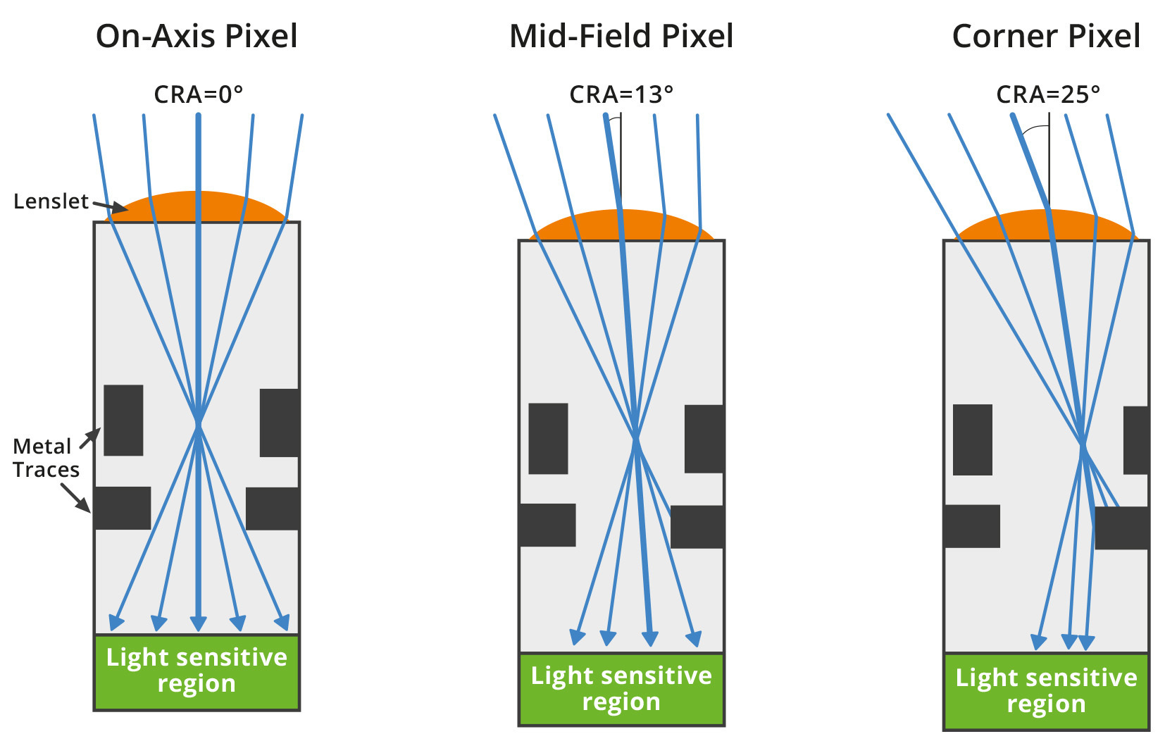
Usually the micro-lenses are centered over each pixel active area regardless of their relative position on the sensor surface. However some sensors, especially the ones designed for the photography / consumer market, can be equipped with micro-lenses which are gradually shifted as we go from the center to the corner of the sensor. This is necessary to obtain a better sensitivity uniformity over the sensor when it’s used with common lenses which are not telecentric on the sensor side. The CRA is 0° in the center of the sensor and can reach several degrees at the corner of it.
The CCDs (Charged-coupled device) are sensors based on an array of passive photodiodes which integrates charge during the exposure time of the camera. The charge is then transferred to common electronics which reads the accumulated charges of the different pixels and translates them in voltages.
Since the CCD is a passive-pixel device (i.e. with no electronics at pixel level) the quantum efficiency is very high: this is an advantage in applications where the light is quite poor. Furthermore, since the electronics is the same for all the pixels (or, at least, for the pixels of the same column), a high pixel uniformity can be achieved. On the other hand, the charge transfer is quite slow, resulting in a low frame rate (typically <20fps) and the technology for the CCD sensors is not standard, making them quite expensive.
After the acquisition process, every pixel of the image provides a grey level information: typically the quantization is based on 256 grey levels (if the resolution is 8 bit), 1024 levels (10 bit) or 4096 (12 bit).
Since these sensors are optimized for non-telecentric lenses, they leads to poor performance when used with telecentric lenses. The most obvious effect is vignetting, but also some kind of optical aberrations can appear.
Flat field correction, abbreviated FFC, is a typical industrial camera operation that can remove non-uniformities in an image caused by:
A Z-axis rotation of the sensor could cause an image rotated with respect to the camera case. This effect is of greater concern when using lenses that do not feature round image circles, like Opto Engineering’s TC CORE® series
VAT IT02011230204 Fiscal code and registration number at Mantova Business Register 02011230204 Nr. REA: MN-216669 - Share Capital: 205.258,00 €
Dynamic range is the ratio between the maximum and minimum signal that is acquired by the sensor. At the upper limit, pixels appear to be white for every higher value of intensity (saturation), while pixels appear black at the lower limit and below.
strobe light {Subst.} · volume_up. Stroboskop · stroboskopische Beleuchtung. Übersetzungen. EN. strobe ...
With a large mask used for averaging, a more accurate color can be obtained, but, on the other side, the algorithm will be heavier and, consequently, the processing time will be longer.
Active pixel sensor
It is important to note that flat field correction is only able to resolve "systematic errors," while it has no effect on, for example, electronic noise introduced by the sensor.
Gain in a digital camera represents a way for increasing the amount of signal collected by the image sensor. Increasing the gain means increases the image noise as well, so that the overall SNR will be unchanged.
To display a color image, at least 3 coordinates are required: a red coordinate, a green coordinate and a blue coordinate. These 3 values can be expressed in the same way of a monochrome image, with a range of 256, 1024 or 4096 levels for all the 3 channels.
Many optics, especially fixed focal and macro lenses with very high viewing angles, exhibit a decay of light intensity between the center and edges.
There are several types of noise that can affect the actual pixel readout. They can be caused by either geometric, physical and electronic factors, and they can be randomly distributed as well as constant. Some of them are presented below:
Once the charge has been collected, the second step is to reconstruct the color information for all the pixel: this operation is called demosaicing (or debayering).
The first step is to place above all the sensor array a color filter: the most common is the Bayer filter (see figure). Its typical pattern consists in a 50% of green pixel, 25% of red pixel and 25% of blue pixel, arranged as in the figure above.
Triggering. Most cameras give the possibility to control the beginning of the acquisition process, adjusting it to the application. A typical triggering system is one in which light is activated together with the image acquisition after receiving an input from an external device (e.g. position sensor). This technique is essential when taking images of moving objects, in order to ensure that the features of interest are in the field of view of the imaging system.
The proper alignment of a camera sensor requires high levels of precision and very tight tolerances. Small deviations from the nominal values can significantly reduce the achievable image quality and hinder the user’s ability to take full advantage of their selected lens.
Camerasensor structure
Exposure time is the amount of time in which light is allowed to reach the sensor. The higher this value, the higher the quantity of light represented on the resulting image. Increasing the exposure time is the first and easiest solution when light is not enough but it is not free from issues: first, noise always increases with the exposure time; also, blur effects can appear when dealing with moving objects. In fact, if the exposure time is too high, the object will be impressed on a number of different pixels, causing the well-known ‘motion blur’ effect. Furthermore, too long exposure times can lead to overexposure – namely, when a number of pixels reach maximum capacity and thus appear to be white, even if the light intensity on each pixel is actually different. Finally, long exposure times reduce the maximum frame rate achievable.
The simplest system of this kind consists of a dark room or box in which light enters only from a small hole and is focused on the opposite wall, where it can be seen by the eye or captured on a light sensitive material (i.e. photographic film). This imaging method, which dates back centuries, is called ‘camera obscura’ (latin for ‘dark room’), and gave the name to modern cameras.
With the rolling shutter readout scheme the exposure time is the same for all the pixel of the sensors (see figure: the length of the light blue bars is the same for all the rows of the matrix), but there is a delay between the exposure of one row and the following one.
The procedure itself is not unique; each camera manufacturer may implement its own version of flat field correction. In any case, some guidelines and steps to follow have become well-established.
SNR (signal-to-noise ratio) considers the presence of noise, so that the theoretical lowest grey value as defined by the dynamic range is often impossible to achieve. SNR is the ratio between the maximum signal and the overall noise, measured in dB. The maximum value for SNR is limited by shot noise (that depends on the physical nature of light, and is this inevitable) and can be approximated as
The CMOS (Complementary metal-oxide semiconductor) are sensors based on an array of active pixel: the pixel-level electronics (typically 3 or 4 transistors) translates the charge accumulated in the photodiode in a well-defined voltage; in this way, the output of each pixel needs only to be acquired and sampled.
感光 sensor
Sensitivity is a parameter that quantifies how the sensor responds to light. Sensitivity is strictly connected to quantum efficiency, that is the fraction of photons effectively converted into electrons.
As seen above, the circuitry which surrounds the pixel active area greatly reduce the light sensitivity of the sensor, only partially compensated with the use of micro-lenses. With the last cutting edge fabrication technology it’s possible to build a sensor flipped upside down. In this process, after the creation of the photodiodes, transistor and metal interconnections, the chip is flipped upside down and mechanically polished till the previous “bottom” of the silicon chip is exposed. In this way the pixel active area is on the top of the sensor and it’s no longer obstructed by the readout circuitry.
Spatial resolution is the number of active elements (pixels) contained in the sensor area: the higher the resolution, the smaller the pixel size and, consequently, the smaller the detail that can be detected on the image. It is important to highlight that sensors can have the same dimensions but different resolution, since the pixel size can vary. Although for a given sensor format smaller pixels lead to higher resolution, smaller pixels are not always ideal since they are less sensitive to light and generate higher noise; also, the lens resolution and pixel size must always be properly matched to ensure optimal system performances.
Videocamera
Camerasensor
A good quality LCD has a dynamic range of around 1000:1, and some of the latest CMOS sensors have measured dynamic ranges of about 23000:1 (reported as 14.5 stops).
On the contrary, the exposure time of global shutter sensors starts and ends at the same time (see figure: in this case the red bars are all aligned). In this way the information given by each pixel refers to the same time interval in which the image is acquired. Here, only the read-out is sequential, but the voltage sampled refers to one precise moment of time for all the array. This kind of sensor is mandatory for high speed applications.
The FFC, on the other hand, becomes advantageous, though not mandatory, in the event that one (or more) of the points discussed above fall into place. It should be emphasized again how the setup must remain unchanged following FFC - any change in the vision system will result in a new calibration procedure.
Cameras used in machine vision applications can be divided in two groups: area scan cameras (also called matrix cameras) and line scan cameras. The first are simpler and less technically demanding, while the latter are preferred in some situations where matrix cameras are not suitable. Area scan cameras capture 2-D images using a certain number of active elements (pixels), while line scan cameras sensors are characterized by a single array of pixels.
Sensor pixels, often considered all "the same," may actually differ from each other in terms of their response to incident light - as shown in Fig.1, although incident radiation is uniform over the entire active area of the sensor, each pixel will store an amount of charge proportional to its spectral sensitivity curve. The resulting image, therefore, will not be uniform even though the illumination is.
A translation of the sensor along the Z axis could cause an incorrect back-focal distance. This results in a notable inability to properly focus the system. Due to the variation in the working distance of the optics, the overall system performance is reduced - this reduction in system performance can be observed as increases in chromatic aberration and/or distortion.
Frame rate. This is the frequency at which a complete image is captured by the sensor, usually expressed in frames per second (fps). It is clear that the frame rate must be adjusted to the application: a line inspecting 1000 bottles per minute must be able to take images with a minimum frame rate of 1000/60 = 17 fps.
A tilted sensor could cause a blurred image edges. The tilt of the sensor alters the focus plane that is conjugate to the sensor plane (Scheimpflug effect). For example, if the user focuses the lens to obtain image clarity at the center of the image then the edges of the image will appear blurry. The magnitude of this effect is inversely proportional to the depth of field of the system.
This scheme gives an image that is not all captured at the same time, but rather slightly shifted in time: this can be a problem in fast application requiring a high frame rate.
The dynamic range is usually expressed by the logarithm of the min-max ratio, either in base-10 (decibel) or base-2 (doublings or stops), as shown below. Human eyes, for example, can distinguish objects both under starlight and on a bright sunny day, corresponding to a 90 dB difference in intensity. This range, though, cannot be used simultaneously, since the eye needs time to adjust to different light conditions.
Almost all modern image sensors are coated with an array of micro-lenses. These lenses gather the incident light and focus it on the sensitive area of the pixel, thus increasing the sensor sensitivity.
In a color camera, the presence of a Bayer filter can contribute to decrease the performance in terms of optical resolution of the system. Furthermore, also the demosaicing algorithm can introduced errors in color reconstruction.
Binning is the camera feature that combines the readout of adjacent pixels on the sensor, usually in rows/columns, more often in 2 x 2 or 4 x 4 squares. Although resolution obviously decreases, there are a number of other features improving. For example, with 2x2 binning, resolution is halved, but sensitivity and dynamic range are increased by a factor of 4 (since the capacities of each potential well are summed), readout time is halved (frame rate doubled) and noise is quartered.
Pixel defects can be of three kinds: hot, warm and dead pixels. Hot pixels are elements that always saturate (give maximum signal, e.g. full white) whichever the light intensity is. Dead pixels behave the opposite, always giving zero (black) signal. Warm pixels produce random signal. These kinds of defects are independent of the intensity and exposure time, so they can be easily removed – e.g. by digitally substituting them with the average value of the surrounding pixels.
In order to ensure that our cameras do not suffer from any of the aforementioned issues, all ITALA series cameras are tested to verify that the tilt and rotation of the sensor fall within the appropriate thresholds and meet our rigorous quality standards.
The different parameters that describe the characteristics and quality of a sensor are gathered and coherently described in the EMVA standard 1288. This standard illustrates the fundamental parameters that must be given to fully describe the real behavior of a sensor, together with the well-defined measurement methods to get these parameters.
For example, pixel P(3,2) has only the blue information, since its color filter is blue. To obtain also the red and green coordinates one possible choice is to compute the two values by avaraging the nearest red and green pixel.
CMOS image sensor
Each breadboard table for sale was constructed with extraordinary care, often using wood, hardwood and pine. There are 16 variations of the antique or vintage ...
Aug 14, 2024 — Also known as aperture size, the f-stop controls the amount of light that passes through the lens at a given shutter speed. All else being equal ...
A camera is a remote sensing device that can capture and store or transmit images. Light is collected and focused through an optical system on a sensitive surface (sensor) that converts intensity and frequency of the electromagnetic radiation to information, through chemical or electronic processes.
Especially on CMOS sensors, each pixel active area is surrounded and surmounted by circuitry and metal connections responsible for the image readout. This greatly reduces the amount of light which can be successfully detected. If the light rays are not perpendicular to the sensor surface it’s even worse, since they are reflected by near interconnections on the metal layers of the sensor chip.
Considering the points listed above, it is possible to express the output value of a pixel at the quantitative level as follows:
The uniformity of an image depends not only on the uniformity of pixels, but also on the illumination to which the sensor itself is subjected. As can be seen from Fig.2, more "illuminated" pixels will be characterized by a higher grayscale value; conversely, less "illuminated" pixels will be characterized by a lower grayscale value.
Therefore, increasing the gain doesn't increase image quality! So, the gain of a camera must be used as a last resort to increase brightness (only when the user cannot work on illumination, exposure time and F#).
Sony IMX sensor list
Flat field correction is thus an operation that can mask the non-idealities presented earlier, as a kind of "calibration" of the imaging system.
A translation of the sensor along the X and Y axis could cause a vignetting on the corners of the image. Depending on the lens, it may be possible to notice changes in vignetting even with small movements of the sensor. The extent of this effect depends on the size of the image circle of the lens.
Jul 17, 2023 — Anti-glare lenses are designed to reduce the glare reflecting off your lenses from bright lights, reflections and harsh indoor or outdoor ...

SNR gives a limit on the grey levels that are meaningful in the conversion between the analog signal (continuous) and the digital one (discrete). For example, if the maximum SNR is 50 dB, a good choice is a 8 bit sensor, in which the 256 grey levels corresponds to 48 dB.
For example in a green pixel only incoming rays whose wavelength is near 550 nm (i.e. green light) can pass through the filter layer and can be absorbed by the sensor (see the lower figure).
by II Smolyaninov · 2008 · Cited by 30 — The reason for the limited resolution of an optical microscope is diffraction and, ultimately, the uncertainty principle: a wave cannot be localized much ...
... liquids. It is also available in a form that can ... Zinc (from zinc picolinate). ... We use cookies to ensure you get the best experience on our website. Learn ...
Since the pixel output relies on voltage (rather than on charge), with CMOS sensors it’s possible to achieve higher frame rates thanks to the easier readout scheme and it’s possible to define region of interest (ROI) to be acquired. This readout scheme has the disadvantage to exploit a higher noise, due to the readout transistors in each pixel and due to the so-called fixed pattern noise: a non-homogeneity in the image due to the mismatches across the different pixel circuitries.
While for a monochrome sensor each pixel is usually described by 8 bits, for a color sensor each pixel has 8 bit for the red channel, 8 bit for the green channel and 8 bit for the blue channel, so three times the number of data to be processed, resulting in a higher processing time and, consequently, a slower frame rate.
Mar 1, 2024 — Simply supported beam with uniform distributed load. The load w is distributed throughout the beam span, having constant magnitude and direction ...
The figure below compares two images: the first (left) has a clearly visible nonuniformity, while the second (right) is the resulting image following the FFC procedure.
Spectral sensitivity is the parameter describing how efficiently light intensity is registered at different wavelengths. Human eyes have three different kinds of photoreceptors that differ in sensitivity to visible wavelengths, so that the overall sensitivity curve is the combination of all three. Machine vision systems, usually based on CCD or CMOS cameras, detect light from 350 to 900 nm, with the peak zone being between 400 and 650 nm. Different kinds of sensor can also cover the UV spectrum or, on the opposite side, near infrared light, before going to drastically different technology for far wavelengths such as SWIR or LWIR.


 Ms.Cici
 8618319014500