
Solid Steel Breadboard - Optical Tables - Catalog - optical plate
Click on the Pair Performance icon in the table below to view experimentally measured coupling efficiency data for the collimator pair as a function of the spacing between the collimators. Although the optimal working distance will slightly deviate for any two individual collimators due to small manufacturing variations, these slight deviations do not significantly affect pair or individual performance. This is evidenced by the data given below, which was taken with randomly selected collimators. To achieve the best possible coupling, we recommend mounting both collimators in kinematic adjustable mounts, such as the POLARIS-K05T6 Mirror Mount with SM05PT Adapter, sold below, for final alignment. All specifications, including beam diameter, beam distance, and pair insertion loss, are guaranteed at a working distance of 100 mm for a collimator pair.
Adapters for the external thread are available (AD1109F) that allow the user to thread the fiber collimator into a mount.
Lensedfiber
However, the use of these adapters results in a stack up of threaded interfaces (threaded fiber connector, threaded collimator, and threaded adapter). As a result, it is possible that unscrewing the fiber connector could inadvertently loosen another thread interface and create an unknown source of instability in the setup.
C-Lenses and GRIN lenses are both cylindrical lenses used for fiber collimation; however, while a GRIN lens has a flat face, a C-lens features a curved face like a traditional convex lens (in this case with a 1.8 mm radius of curvature). Refracting light in this way allows for longer working distance collimators with lower insertion loss than our GRIN collimators for applications requiring more involved free-space beam manipulation. For Thorlabs' complete selection of fiber collimators, please see the Collimator Guide tab.
FiberCollimator
J-50MB-LE Specifications Wavelength Range 190 - 12000 nm Energy Range 250 μJ to 500 mJ Maximum Energy Density 500 mJ/cm2 10ns @ 1064nm Maximum Average Power 10 W Maximum Pulse Width 57 μsec Maximum Rep Rate 300 pps Active Area Diameter 50 mm Calibration Wavelength 1064 nm Calibration Uncertainty 2% Detector Coating MaxBlack Dimensions Ø76 x 16 mm RoHS Compliant Yes
Ideally, 100% of the light emitted by the first fiber would be coupled into the second fiber, but some light will always be lost due to reflections, scattering, absorption, and misalignment. Misalignment, typically the largest source of loss, can be minimized using the alignment and stabilization techniques described in this video.
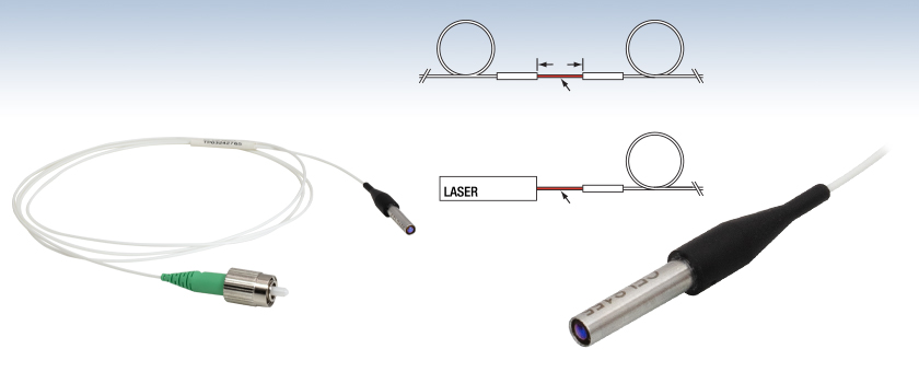
Free-Space CouplingWhen using C-lens collimators to couple a free-space beam into a fiber, precise alignment is needed for good coupling efficiency. We recommend using a kinematic tip and tilt mount and lens tube adapter, paired with an XYZ adjustable platform (such as ourPOLARIS-K05T6 Mirror Mounts, SM05PT Adapters, sold below, and MT3 XYZ Translation Stages), or our 6-axis kinematic mount paired with a lens tube adapter (Item #s K6XS and SM1PT, sold below).
Thorlabs offers pigtailed fiber collimators that use C-lenses. These C-lens collimators feature a Ø1.8 mm clear aperture and are coupled to SMF-28 Ultra single mode fiber. They are designed to be used in pairs, with a free-space beam between the lenses, and can also be used individually. We offer models centered at 1550 nm with a choice of an unterminated scissor-cut fiber end, a 2.0 mm narrow key FC/PC connector, or a 2.0 mm narrow key FC/APC connector.
These adapters are designed to mount Thorlabs' C-Lens Fiber Collimators in SM05- or SM1-compatible mounts, lens tubes, and cage components. The adapters' design ensures that the C-lens is aligned with the optical axis when mounted into a lens tube. A 1/16" (1.5 mm) hex, nylon-tipped setscrew is used to press the C-lens fiber collimator against the two lines of contact created by the double-bored mounting hole. Additionally, each adapter has holes on opposing sides of the central bore for use with a spanner wrench. The SM05PT is compatible with the SPW908 spanner wrench while the SM1PT is compatible with the SPW801 and SPW909 spanner wrenches.
This Post-Mountable Ferrule Clamp allows C-Lens Collimators to be mounted securely and compactly within an experimental setup. The collimator is clamped into the flexure mount using a 5/64" (2 mm) hex key. An 8-32 (M4) tapped hole on the bottom of the mount provides compatibility with our Ø1/2" optical posts.
Edmund Optics LED
Fiber collimators are often used to introduce light into an optical setup from a fiber coupled source. Thorlabs offers a variety of fiber collimator packages, some only provide a smooth barrel (like the triplet collimators) and others have a metric thread at the end of the barrel (like the asphere collimators).
In this demonstration, the first fiber is single mode. The optical power incident on the second collimator, as well as the power output by the second fiber, are measured. When the second fiber is multimode with a 50 µm diameter core, alignment resulted in 91% of the power incident on the second collimator being measured at the fiber output. This value was 86% when the second fiber is single mode. Some differences in collimator designs, and their effects on the characteristics of the collimated beams, are also discussed.
How to collimate light from afiber
Thorlabs' FiberBench, which can accommodate pre-aligned FiberPort collimators and allows modular optical components to be placed in the beam path, is offered for modular fiber/free-space setups.
For this reason, Thorlabs suggests epoxying the threaded fiber collimators into the threaded mounts if that mounting mechanism is preferred.
Collimator Pair with Free-Space BeamOur C-lens pigtailed collimators are designed to be used in pairs, with a free-space beam between the lenses (see photo to the left). This free-space beam can be manipulated with many types of optics prior to entering the second lens. The collimators should be placed with a spacing of 100 ± 10 mm (working distance) between the front lens surfaces for maximum coupling efficiency. When used within the specified working distance and mounted on tip-tilt mounts as described in Free-Space Coupling, above, typical insertion losses of less than 0.2 dB are possible.
Two collimators, inserted into a fiber optic setup, provide free-space access to the beam. The first collimator accepts the highly diverging light from the first fiber and outputs a free-space beam, which propagates with an approximately constant diameter to the second collimator. The second collimator accepts the free-space beam and couples that light into the second fiber. Some collimation packages, including the pair used in this demonstration, are designed for use with optical fibers and mate directly to fiber connectors.
For both packages, Thorlabs typically suggests the use of an adapter with a nylon tipped set screw that holds the barrel against a two line contact.
If you would like more information about tips, tricks, and other methods we often use in the lab, we recommend our other Video Insights. In addition, our webinars provide practical and theoretical introductions to our different products.


 Ms.Cici
 8618319014500