
Fiber optic network: advantages and definition - optical fiber
When forward biased, different colour LEDs start to conduct at different forward bias voltages. RED LEDs are turned on most easily requiring a little less than 2 V whereas the BLUE LEDs require a higher forward bias voltage of closer to 3 V. Note that in all cases LEDs require a greater forward bias voltage than regular silicon diodes which only require 0.7 V.
An LED is forward biased when current can flow from the anode to the cathode. When current flows through the LED there is a potential difference across the LED of around 2 V although this can depend on the type and colour of LED being used. If the supply voltage is less than 2 V no current will flow and the LED will not light.
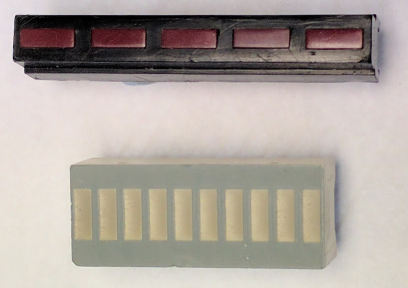
An LED array is simply a series of individual LEDs packaged together to make a single display unit. The LEDs are all electrically separate and each element of the array requires a series resistor. These are useful for bar graphs and VU meters as well as being used to make futuristic looking machines in old school Si-Fi movies.
High power LEDs are just like regular LEDs except that they (a) often require a heatsink (b) take a LOT more current and so can not be easily controlled directly by logic gates etc and (c) are very bright so you need to take care not to damage your eyesight.
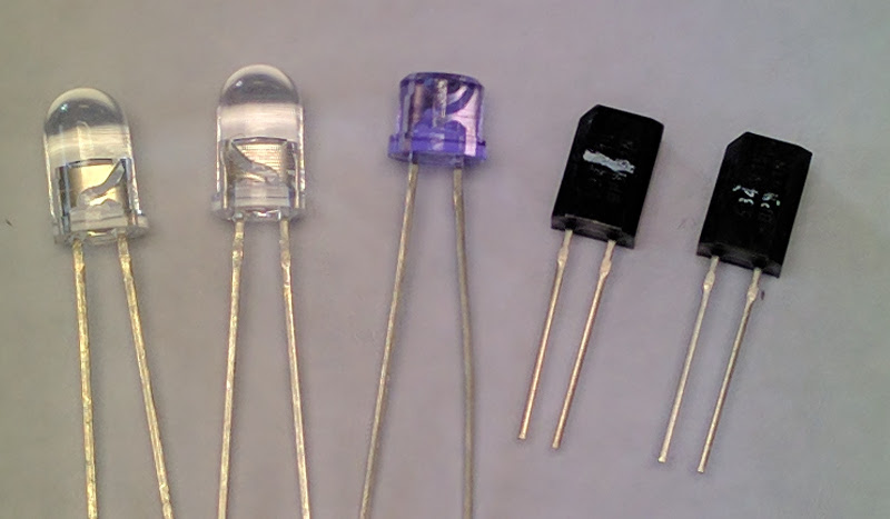
The humble LED used in school electronics comes in many shapes and sizes but, most commonly, they are circular with a diameter of 5 mm and come in a range of colours from Red to Blue.
Light Emitting Diodes (LEDs) are ubiquitous in electronics and are the focus of much current research and development. LED bulbs provide environmentally acceptable alternatives to traditional incandescent bulbs, LED lasers power the Internet and OLED displays have revolutionised smart phones and TVs.
Opto Engineeringlens
To calculate the value of the series resistor, calculate the potential difference across the resistor. In the example the supply voltage is 9 V and the LED forward bias voltage is 2 V therefore the voltage across the resistor is 7 V. Knowing the desired current through the LED (and therefore through the resistor) use the resistor equation to calculate the value of the series resistor. In the example V = 7 V and I = 10 mA giving:R = 7 ÷ 0.01 = 700 ΩChoose the most appropriate resistor form the E24 series.
The 7 segment display is an arrangement of 7 LEDs and a separate LED for the decimal place. The display can form the digits 0-9 to display decimal numbers and can also form the letters A-F allowing Hexadecimal to be displayed. The more complex 16 segment display can be used to display all the letters of the alphabet.
C-MountLens
Like a silicon diode, LEDs have an anode and a cathode. The cathode is marked by a flat side on the LED casing and by the shorter of the two legs. It is important to know which way round to connect an LED as they only allow current to flow in one direction which is from the anode to the cathode.
In a 'Common Cathode' 7-segment display the cathodes of all eight LEDs are connected to a common pin which is connected to 0 V. Each separate segment of the display should have its own series resistor. Each segment is connected to +Ve to illuminate the display. In a 'Common Anode' 7-seg display, all eight anodes are connected to a common pin which is connected to the +Ve supply. Each segment is connected separately to 0 V via its own series resistor to illuminate the display.
Get cameraslens
Infrared (IR) LEDs are exactly like regular LEDs except that they do not emit visible light. This makes them harder to test therefore a multimeter must be used. IR LEDs are commonly used in remote control handsets for TVs etc or in IR security lighting.
Machine Visionmacro lens
In almost all cases LEDs are used with power supplies greater than 2 V and a series resistor is essential to stop the LED being damaged. In this case the series resistor limits the current flowing through the LED.

If the reverse bias voltage across an LED is too great (> about 20 V) then the LED can be damaged. To avoid this a regular silicon protection diode can be connected in parallel with the LED but the other way round. When the LED is reverse biased, the diode is forward biased and will conduct through the LED's series resistor. As the diode is conducting, the potential difference across the diode, and hence across the LED, is limited to around 0.7 V which is perfectly acceptable. When the LED is forward biased and hence lit, the protection diode is reverse biased and does not conduct.
All LEDs have a different forward bias voltage and a different optimal current. As a general rule, normal 5 mm indicator LEDs have a forward bias voltage of about 2 V and take a current of about 10 mA to 20 mA. This means they can easily be controlled directly by logic gates and Op-Amps.


 Ms.Cici
 8618319014500