
Refractive index of Norland NOA 61 - norland glue
... color. Did I get the wrong result? Scoring 0% means you did not answer correctly on any of the test images targeting that cone. It does not mean that you ...
May 21, 2019 — In this thread can post anybody who have a V3 factory sample version of A119 sent by @viofo After my first tests I can say the Sony IMX335 ...
For DIC imaging, Thorlabs offers N1 and N2 dry condenser prisms as well as N1 and N2 dry objectives. Note that an objective will have an N1 or N2 engraving to denote compatibility with a condenser prism.
ResolutionThe resolution (δ ) of the microscope describes its ability to image two closely spaced points as a separable pair, instead of as a single point. A common equation,
Circularly polarizedlight
Trans-illumination illuminates from the opposite side of the sample as the viewing apparatus. Example imaging modalities include brightfield, differential interference contrast (DIC), Dodt gradient contrast, oblique, and darkfield microscopy. Click here for additional information on trans-illumination with Cerna.
Illumination Light PathThe illumination path begins with the light source and passes through the sample to the camera sensor. The video animation (Video 1, below) traces rays from an extended source, like a lamp or LED, through this light path.
Figure 3: Cones describe the light incident on a sample point from the condenser (left, gold), the light transmitted through the sample (right, yellow), and the range of light the objective can collect (right, orange). The cones' angles are measured from the optical axis. The angular ranges of the light cones incident on and transmitted by the sample are approximately the same (θcd ), since light that is not absorbed or scattered by the sample travels in an approximately straight line. The angular range (θobj ) accepted by the objective lens is can be different. The numerical apertures of the condenser (NAcd ) and objective (NAobj ) are often used to compare the angular ranges of the transmitted light to the light the objective lens can gather.
Circular polarization is relatively rare in nature, and almost never appears as a major component in natural scenes. It has been observed in light internally reflected from the underside of the sea's surface [18], where it arises from light originally linearly polarized by in-water scattering. Surprisingly, however, circular polarization is produced by several groups of animals. Larval fireflies emit circularly polarized light, by an unknown mechanism, from their bioluminescent lanterns [31]. Many species of scarab beetles reflect circularly polarized light, produced by a helical arrangement of chitin lamellae forming a chiral structure in their exoskeleton [32,33]. Stomatopod crustaceans of various species also reflect circularly polarized light, which they use for visual signalling [34]. Perhaps, the occasional use of circular polarization by animals is useful because it is rare in scenes, and thus prominent when used, but at this point research on biological aspects of circular polarization is still in its infancy.
How polarized light is distributed throughout the overall underwater light field is highly variable, even at a single geographical location at a single time of day. Unlike the situation in air, where the celestial polarization field is reasonably constant with small changes in height or altitude, underwater, the polarization fields at depths separated by only a few metres or tens of metres can be extremely different. In part, this is a consequence of vertical variations in the amount and the quality of suspended material. A much more significant effect, however, is produced at shallow depths by variations in the relative contributions of the aerial polarization field, transmitted into water but refracted at the water's surface, and the internal submarine light field produced by scattering within the water itself. The refractive index change between air and water restricts the view of the sky to a conical viewport (called Snell's window in deference to Snell's law of refraction) about 96° in diameter, within which the aerial polarization field may be visualized [7]. Outside Snell's window, polarized light is produced by scattering of downwelling sunlight. Near the surface, especially when the water is calm and clear, and there are few waves or ripples, polarization in the sky is readily observed (figure 4). As depth increases, multiple-path scattering destroys the remnants of the celestial pattern, and only in-water scattering, produced relatively near the observer, creates the polarization field.
The first detailed examination of the overall pattern of polarized light in natural water was initiated by Waterman [15], who used a visual polarization analyzer (an axis-finder) to estimate the polarization distribution in shallow marine water (approx. 2–3 m depth) at different times of the day. At this relatively shallow location, the features of the aerial polarized-light distribution were obvious. The development of a submersible spectropolarimeter permitted Cronin & Shashar [16] to continue from this pioneering work, making spectral measurements of polarization at 25 points throughout the upper hemisphere at a depth of 15 m in marine waters. This second set of measurements differed from Waterman's [15] set in that the greater distance between the instrument and the water's surface was sufficient to obliterate the aerial pattern (figure 5). Shashar et al. [17] showed that even in clear natural water, polarization is reduced by 50 per cent owing to multiple-path scattering as light passes through each 2–4 m of water, so at 15 m depth there would be little to no trace remaining of celestial polarization. Instead, scattering of incident sunlight, arriving at its refracted angle after transiting the water's surface, is entirely responsible for the observed polarization at this depth. Consequently, the distribution of polarization is centred on the refracted position of the Sun, which is easily observed in the panels of figure 5 as the Sun moves from east to west in the refracted sky.
Large and small experiment mounting options are available to take advantage of the large working space of this microscope. Click here for additional information about mounting a sample for microscopy.
Jul 13, 2022 — Von klassisch bis abgefahren – 8 Besondere Makro Objektive · Laowa 65mm F/2,8 2x Ultra Macro · Canon MP-E 65mm F/2,8 1-5x · Laowa 24 mm F/14 ...
For sample viewing, Thorlabs offers trinoculars, double camera ports, and camera tubes. Light from the sample plane can be collected via cameras, photomultiplier tubes (PMTs), or custom setups using breadboard tops. Click here for additional information about viewing samples with a Cerna microscope.
While the Sun's position in the sky continues to strongly influence the underwater polarization pattern at moderate depths, sunlight is increasingly diffused at greater depths owing to continuous scattering. In addition, absorption of sunlight oriented away from the zenith, owing to the large paths through water at depth, gradually creates a stable, or asymptotic, light field centred on the zenith that varies little if at all in its radiance distribution throughout the day [18,19]. Thus, throughout most of the ocean's depths where sunlight is able to penetrate (to approx. 1000 m in the clearest water), the polarization pattern is stable, with the e-vector oriented within a few degrees of horizontal (see [20]). Even near the surface, refraction confines the apparent position of the Sun to the bounds of Snell's window, limiting angular variation in e-vector orientation (figure 5).
Working Height: The height of the support rail of the microscope body plus the height of the base. The size of the working height, along with the throat depth, determine the working space available for microscopy.
Electric polarization
Dovetail: A form of mechanical attachment for many microscopy components. A linear dovetail allows flexible positioning along one dimension before being locked down, while a circular dovetail secures the component in one position. See the Microscope Dovetails tab or here for details.
Epi-illumination illuminates the sample on the same side as the viewing apparatus. Example imaging modalities include fluorescence, confocal, and reflected light microscopy. Click here for additional information on epi-illumination with Cerna.
Condenser and ObjectiveIn transmitted light microscopy, the condenser collects light from the source and illuminates the sample (Figure 1). The condenser optica system typically includes several optical elements, which can be aligned to provide uniform illumination of the sample plane. The objective lens is located on the opposite side of the sample plane and collects the light that is transmitted through the sample. This light is then routed to create an image at an eyepiece or camera.
Microscope objectives are held in the optical path of the microscope via a nosepiece. Click here for additional information about viewing a sample with a Cerna microscope.
Polarization visible through the air–water interface at a depth of approximately 5 m in a coral-reef habitat at Horseshoe Reef, Lizard Island, Australia at sunset on 10 September 2003. Images were collected using a digital camera in a submersible housing fitted with a rotatable linear polarizer, and series of three sets of images were analysed for degree and angle of polarization. The camera was angled upward so as to image the zenith (indicated by a tethered float at the position of the arrow in each image); south is to the bottom of the image and west is to the right. The edges of Snell's window (where the image of the sky terminates) lie near the arc of rippled water near the bottom of each panel. The top panel shows the degree of polarization in false colour, while the bottom panel shows the angle of polarization (e-vector angle); colour keys are provided to the right. Note that the skylight pattern of polarization is visible underwater at this depth to the edge of Snell's window, although the degree of polarization is reduced somewhat from what would be visible in air (e.g. figure 2). Below Snell's window, polarization was oriented horizontally (not shown), but the band of overhead polarization is vertically polarized in the image, being oriented north/south. The small patches of random false colour near the margins of Snell's window are owing to differences in the three photographic frames used for the analysis (mostly caused by ripples at the surface); the float also drifted slightly between photographs and thus is multi-coloured in these images.
Image of the Light SourceAn image of the light source at the sample plane would not uniformly illuminate the sample (Figure 4, left, for example), since the light-emitting structures are clearly visible in images of the source. Köhler illumination instead uniformly illuminates the sample plane (Figure 4, right) by providing the light to the sample plane as bundles of parallel rays. In addition, aligning the system to provide Köhler illumination prevents the light source from being imaged at the camera sensor, which would superimpose an image of the light-emitting structures onto the image of the sample.
To support home-built Cerna® microscope systems, Thorlabs offers four achromatic condensers. Designed for upright microscopes, these condensers collect light emitted by an illumination source to illuminate transmissive samples from beneath the objective. They are used in several transmitted light imaging modalities, including brightfield illumination, Dodt contrast, and differential interference contrast (DIC) imaging, and have an internal turret or tray to mount one or more condenser prisms, illumination masks, and/or other optics.
Figure 4: An image of the source includes the structure of the light emitting elements (left). Köhler illumination avoids imaging the source to the sample or sensor planes and provides uniform illumination to the sample plane (right).
Circular polarization
As an example, when the objective lens has a 0.7 NA with air (n = 1) between the lens and sample, the lens' angle of acceptance is θ = θobj = 44.43°. For the system illustrated in Figure 2, the NA of the illumination and the NA of the collected light are the same, since both light paths pass through the objective lens.
Bayonet Mount: A form of mechanical attachment with tabs on the male end that fit into L-shaped slots on the female end.
Numerical ApertureThe condenser provides light to the sample plane over a range of different angles (Figure 3). A cone, drawn with its tip at a point on the sample and its base encircling the light from the condenser, can be used to quantify the range of incident angles (θcd ). The light transmitted by this point on the sample has approximately the same angular range. A different cone can be used to depict the angular range of light (θobj ) the objective lens is capable of gathering.
To learn which dovetail type(s) are on a particular component, consult its mechanical drawing, available by clicking on the red Docs icon () below. For adapters with a female dovetail, the drawing also indicates the size of the hex key needed for the locking setscrew(s). It is important to note that mechanical compatibility does not ensure optical compatibility. Information on optical compatibility is available from Thorlabs' web presentations.
Secure .gov websites use HTTPS A lock ( Lock Locked padlock icon ) or https:// means you've safely connected to the .gov website. Share sensitive information only on official, secure websites.
Filter Cube: A cube that holds filters and other optical elements at the correct orientations for microscopy. For example, filter cubes are essential for fluorescence microscopy and reflected light microscopy.
The table below gives the dovetail, optical component threads, and cage system interfaces that are present on each DIY Cerna component. If a DIY Cerna component does not have one of the standard interfaces in the table, it is not listed here. Please note that mechanical compatibility does not ensure optical compatibility. Information on optical compatibility is available from Thorlabs' web presentations.
Epi-Illumination: Illumination on the same side of the sample as the viewing apparatus. Epi-fluorescence, reflected light, and confocal microscopy are some examples of imaging modalities that utilize epi-illumination.
Schechner & Karpel [27] described a particularly effective approach that relies on subtle differences between image pairs acquired through polarizers oriented orthogonally. Their idea is based on the recognition that generation of veiling light in water is closely related to polarization, since both processes result from scattering of naturally incident light. Furthermore, loss of object visibility also results in part from scattering, as light originally reflected from objects becomes scattered away and mixed with haze produced between the object and the viewer. If the haze can be removed, and the original intensity and colour of the object restored by estimating its original reflectance, compensating for scattering and absorption of light by the intervening water, the scene can be restored to the view that would be available in a clear, non-scattering medium. Schechner & Karpel's [27] approach uses the relationship between polarization and the quantity of intervening haze, which they call ‘backscatter’. Lythgoe [30] termed this light, when it appears in front of viewed objects, ‘veiling light’. If the backscatter is polarized, but light coming from the object is not, it is possible to estimate the backscatter by comparing two polarization images. An additional benefit of this approach is that the distance to an object can be estimated by the quantity of backscatter between it and the observer. The quantity of backscatter at effective infinity, and the degree of polarization created by scattering, can both be estimated from portions of the image that include only the background water. The method is very sensitive to small variations in these estimates, which might arise from inhomogeneity in lighting or from different amounts of scattering along different visual axes (particularly away from the horizontal), but it can be extremely effective in both removing haze and restoring object radiance. If the correction is done independently for different colour channels in an image, the resulting image is largely colour-corrected as well. See examples in figure 7, where the Schechner & Karpel approach produces very satisfying colour and haze correction.
The CSC2001 works out-of-the-box with objectives ranging from 10X to 100X by adjusting the cone of illumination with the aperture diaphragm. For compatibility with 4X objective lenses, we offer the C4X lens, which is easily positioned within the CSC2001 using a CN1 tray (all items sold separately). For C4X specifications see the table below.
We thank N. Shashar and N. Roberts for many interesting discussions. This work is based on research supported by the National Science Foundation under grant number IOS 0721608, by the Air Force Office of Scientific Research, grant number FA9550-09-1-0149, and by the Asian Office of Aerospace Research and Development, grants number AOARD 064040 and 074086.
Thorlabs offers various light sources for epi- and trans-illumination. Please see the full web presentation of each to determine its functionality within the Cerna microscopy platform.
Thorlabs manufactures many components which use dovetails to mate with our own components or those of other manufacturers. To make it easier to identify dovetail compatibility, we have developed a set of dovetail designations. The naming convention of these designations is used only by Thorlabs and not other microscope manufacturers. The table to the right lists all the dovetails Thorlabs makes, along with their key dimensions.
Since the upper atmosphere continues to be illuminated by sunlight even when the Sun itself is not visible below the horizon, skylight polarization is still present and may be used by animals for orientation during the period of twilight [12,13]. Patterns of skylight polarization throughout the entire twilight period have been examined using whole-sky imaging polarimetry and polarization spectrometry [14], demonstrating that the simple overhead pattern of skylight polarization exists for nearly an hour before sunrise or after sunset (figure 3). Thus, when the sky is clear or even moderately cloudy, skylight polarization from the Sun is visible and potentially usable by animals throughout most of the day, and exists nearly around the clock at times when the Moon is visible and bright at night.
A microscope objective collects and magnifies light from the sample plane for imaging. On the Cerna microscope, the objective is threaded onto a nosepiece, which holds the objective at the throat depth, or the distance from the optical path to the support rail of the microscope body. This nosepiece is secured to a motorized focusing module, used for focusing the objective as well as for moving it out of the way for sample handling. To ensure a light-tight path from the objective, the microscope body comes with a bellows (not pictured).
Wratten zijn meestal dikke, bloemkoolachtige uitgroeisels van de huid. Wratten voelen vaak ruw aan. De medische benaming is verruca. Wratten zitten vooral op de ...
used to estimate this minimum separation includes only the wavelength () and the NA of the objective (NAobj ). While this equation seems to suggest the NA of the condenser (NAcd ) does not affect resolution, this is not the case. This equationactually assumes that NAcd ≥ NAobj .
Imaging Light PathThe imaging path begins at the sample plane and ends at the camera sensor, and the video animation also traces rays through this light path. Each point on the sample is imaged to a point on the camera sensor.
Official websites use .gov A .gov website belongs to an official government organization in the United States.
The resolution of microscopy images is affected by several factors, including the numerical aperture (NA) of the condenser lens and the uniformity of the sample plane illumination. The NA of the condenser lens should be at least as large as the NA of the objective lens. Under these conditions, the condenser lens illuminates the sample over a range of angles that is at least as wide as the range of angles over which the objective lens collects light from the sample. In order to provide uniform illumination of the sample plane, a technique called Köhler illumination is often used. An important result of this illumination approach is that the source and sample are never imaged to the same plane. The following include more information about the relationship between the condenser and objective lenses, as well as Köhler illumination:
Image enhancement via polarization processing using the approach of Schechner & Karpel [27] on two sets of underwater images. The original input images are illustrated at the left, taken as pairs with polarizing filters horizontal or vertical as shown by the double-headed arrows. None of the images, either original or analysed, has been altered in any way. Note that the input images differ only subtly, and neither has much contrast nor much colour saturation. Also, the colour tends towards hazy blue with increasing distance into the scene. After analysis for backscatter and degree of polarization at each pixel, the analysed image recaptures much of the inherent contrast in the scene and restores colour. Note how the objects deeper into the scene in particular recover their contrast and their inherent colour.
Polarization oflight
ImageMagick supports multispectral images where all channels have the same dimensions and number of pixels as the original image. However, not all image formats ...
For customers interested in machining their own dovetails, the table to the right gives the outer diameter and angle (as defined by the drawings below) of each Thorlabs dovetail designation. However, the dovetail's height must be determined by the user, and for circular dovetails, the user must also determine the inner diameter and bore diameter. These quantities can vary for dovetails of the same type. One can use the intended mating part to verify compatibility.
The microscope body provides the foundation of any Cerna microscope. The support rail utilizes 95 mm rails machined to a high angular tolerance to ensure an aligned optical path and perpendicularity with the optical table. The support rail height chosen (350 - 600 mm) determines the vertical range available for experiments and microscopy components. The 7.74" throat depth, or distance from the optical path to the support rail, provides a large working space for experiments. Components attach to the body by way of either a linear dovetail on the support rail, or a circular dovetail on the epi-illumination arm (on certain models). Please see the Microscope Dovetails tab or here for further details.
New VSTECH product line with 3 fixed focus options and advanced focus shift feature.
Since an image of the source is at the front focal plane of the condenser lens, only bundles of parallel rays are incident on the sample plane. No source image is formed at the sample and the illumination is uniform.
Condenser Mounting with D3N DovetailThese condensers can be mounted to a condenser holder using the male D3N dovetail on the bottom. D3N is Thorlabs' designation for the dovetail used by the majority of Nikon condensers for upright microscopes. See the Microscope Dovetails tab for more information.
The CSC2001 contains an internal slot that accommodates trays designed to mount various optics. Magnets in the tray and inside the slot ensure easy exchange and repeatable positioning of optics within the condenser. The CSC2001 condenser comes with one C32 tray for mounting Ø32 mm optics. Additionally, we offer the CN1 and CN2 trays for use with DIC condenser prisms and the CSM tray for mounting Ø1" optics. For tray specifications see the table below.
Skylight polarization produced by moonlight has been much less studied than that originated by the Sun, but its distribution and properties generally mimic those of the daytime sky, being different primarily in intensity [8]. Some nocturnal animals, in fact, are known to orient to polarization produced by the Moon ([9]; see also [10]). Because moonlight competes with other nocturnal sources of light in the sky, even in nature, the degree of polarization is expected to be less than in a similarly clear daytime sky, especially when the Moon is not full. Also, artificial light sources will severely corrupt the natural nocturnal pattern of celestial polarization, but these have essentially no effect on the pattern during the day. Celestial polarization survives poorly in hazy or cloudy conditions, as the presence of suspended particles or water droplets rapidly depolarizes light by multiple-path scattering. Nevertheless, if the sky is not entirely covered in cloud, the patches of open atmosphere that are visible from the Earth's surface retain the polarization characteristic of their relationship to the Sun [11]. Thus, animals that rely on celestial polarization can continue their activities as long as the sky is not completely occluded by haze or clouds (figure 2).
This overview was developed to provide a general understanding of a Cerna® microscope. Click on the different portions of the microscope graphic to the right or use the links below to learn how a Cerna microscope visualizes a sample.
Alternately, the microscope can be configured so the objective both illuminates and collects light from the sample (Figure 2). In this case, there is no separate condenser lens system.
Dovetails are used for mechanical mating and optical port alignment of microscope components. Components are connected by inserting one dovetail into another, then tightening one or more locking setscrews on the female dovetail. Dovetails come in two shapes: linear and circular. Linear dovetails allow the mating components to slide before being locked down, providing flexible positioning options while limiting unneeded degrees of freedom. Circular dovetails align optical ports on different components, maintaining a single optical axis with minimal user intervention.
Throat Depth: The distance from the vertical portion of the optical path to the edge of the support rail of the microscope body. The size of the throat depth, along with the working height, determine the working space available for microscopy.
Using the Cerna microscope body, a sample can be illuminated in two directions: from above (epi-illumination, see yellow components to the right) or from below (trans-illumination, see orange components to the right).
Figure 1: In transmitted light microscopes, light from the light source is directed to the sample by the condenser optical system. The objective lens is used to collect the transmitted light. This collected light is then routed to create an image at a camera or eyepiece.
Bellows: A tube with accordion-shaped rubber sides for a flexible, light-tight extension between the microscope body and the objective.
Source light transmitted through the sample plane is imaged to the objective back focal plane, which is located between the objective and tube lenses. No image of the light source is formed on the camera sensor, which preserves image quality.
The LCPN1 and LCPN5 adapters allow the user to attach a custom-built condenser or other light conditioning module to a Cerna, inverted Nikon Eclipse Ti, or upright Nikon Eclipse microscope. The adapters utilize the same male D3N dovetail as the above condensers; see the Microscope Dovetails tab for details. The LCPN1 adapter features internal SM30 (M30.5 x 0.5) threading for Ø30 mm lens tubes; two SM30RR retaining rings are included to secure an optic inside the adapter. The LCPN5 adapter features SM2 (2.035"-40) threading for SM2 lens tubes and includes one SM2RR retaining ring. Both adapters have four through holes with side-located locking setscrews (5/64" [2 mm] hex) that can be used to attach Ø6 mm cage rods for 60 mm cage systems. Additionally, the LCPN1 adapter features 4-40 tapped holes on 30 mm centers, located on the side opposite the dovetail, which can be used for 30 mm cage systems.
These achromatic air condensers are designed to be used with dry objectives. They are equipped with an adjustable aperture stop diaphragm that is controlled by a lever on the side, as shown in the below drawing.
Each of the multiple light-emitting points on the source radiate light over a range of angles. The collector lens gathers this light and transmits a beam whose maximum diameter is limited by the field stop. The light is then incident on the field lens, which forms an image of each source point at the aperture stop. The alignment of the source image at the aperture stop is critical, since the aperture stop is positioned at the front focal plane of the condenser lens.
Natural sources of light are at best weakly polarized, but polarization of light is common in natural scenes in the atmosphere, on the surface of the Earth, and underwater. We review the current state of knowledge concerning how polarization and polarization patterns are formed in nature, emphasizing linearly polarized light. Scattering of sunlight or moonlight in the sky often forms a strongly polarized, stable and predictable pattern used by many animals for orientation and navigation throughout the day, at twilight, and on moonlit nights. By contrast, polarization of light in water, while visible in most directions of view, is generally much weaker. In air, the surfaces of natural objects often reflect partially polarized light, but such reflections are rarer underwater, and multiple-path scattering degrades such polarization within metres. Because polarization in both air and water is produced by scattering, visibility through such media can be enhanced using straightforward polarization-based methods of image recovery, and some living visual systems may use similar methods to improve vision in haze or underwater. Although circularly polarized light is rare in nature, it is produced by the surfaces of some animals, where it may be used in specialized systems of communication.
Polarization underwater at a wavelength of 500 nm throughout the day. Data were collected at the Aquarius underwater laboratory in Key Largo, FL, USA on 15 and 16 August 1999 (see also [16]). Times given are Eastern Standard Time. Each part of the figure shows the polarization pattern looking upwards (this is why east and west are reversed from their positions on a compass card). The margin of each panel represents horizontal, and the concentric circles show elevations at 30° intervals. The lighter inner circle indicates the region within Snell's window, where skylight is visible through the sea's surface. At each location of measurement, the e-vector angle is plotted as the angle between a tangent to the elevation circle, and the degree of polarization is coded by the thickness of the plotted line (see the key at the lower right). The estimated position of the Sun at the midpoint of each series of measurements is indicated by the yellow symbol within Snell's window.
Trans-illumination illuminates from the opposite side of the sample as the viewing apparatus. Example imaging modalities include brightfield, differential interference contrast (DIC), Dodt gradient contrast, oblique, and darkfield microscopy. Trans-illumination modules, which condition light (on certain models) and direct it along the optical path, are attached to the support rail of the microscope body via a linear dovetail (see Microscope Dovetails tab or here). Please note that certain imaging modalities will require additional optics to alter the properties of the beam; these optics may be easily incorporated in the optical path via lens tubes and cage systems. In addition, Thorlabs offers condensers, which reshape input collimated light to help create optimal Köhler illumination. These attach to a mounting arm, which holds the condenser at the throat depth, or the distance from the optical path to the support rail. The arm attaches to a focusing module, used for aligning the condenser with respect to the sample and trans-illumination module.
Light arriving on Earth from natural sources, either directly from the Sun or reflected from the Moon, is unpolarized or, at most, weakly polarized. Nevertheless, there is an abundance of polarized light in natural scenes, whether in the air, on the surface of the Earth, or underwater. This seemingly paradoxical situation arises because polarized light is readily produced by the interactions of unpolarized light with materials, particles and surfaces. Here, we consider some features of light's polarization in nature, focusing on its formation and distribution as well as some of its properties useful to animals and to humans.
In a depolarized non-diverging beam of light, photons travel in parallel but have randomized axes of electric field vectors (or e-vectors). From such a beam, fully or partially linearly polarized light can be produced by differential absorption, differential reflection or differential scattering of subsets of these photons (figure 1). Thus, when light impinges on a dielectric surface that can reflect specularly, the reflected beam is commonly partially linearly polarized (in other words, it contains a non-random mix of e-vectors, producing an average e-vector orientation in a single plane—therefore, linearly polarized light is also called plane-polarized light). Also, if this surface is transparent and permits refraction, the refracted beam entering the surface is itself polarized. Similarly, partially polarized light results from scattering from dispersed or suspended particles. In nature, reflection from dielectric surfaces such as calm water, wet features, leaves or other shiny non-metallic objects is often polarized. These reflections produce patterns of polarized light that are specific to a given scene, depending on the types and orientations of surfaces in the scene. The patterns can change rapidly as these surfaces move and change in orientation, and can vary as the source of light (e.g. Sun or Moon) changes position. In contrast, scattering in bulk media, such as the atmosphere or underwater, produces a stable polarization field that varies only slowly with time and is largely predictable, depending on the types of scattering particles and on the orientation of the illuminant. Thus, in nature, both the Sun and the Moon can launch predictable polarization fields that are useful for orientation or for enhancing object visibility. In this review, we will discuss such patterns, considering primarily patterns of linearly (or plane) polarized light. However, circularly polarized light, while rare in nature, is sometimes present and will be discussed briefly as well.
Degree of polarization
Polarized light is abundant in natural scenes, and has the special attribute in such scenes of having been produced locally, almost always either by scattering or reflection. Thus, the patterns of polarized light visible to animals with polarization vision or to artificial instruments sensitive to light's polarization provide abundant information about objects in the scene, location of the Sun and time of day. Furthermore, natural polarization distributions can be used to enhance information indirectly, either simply by minimizing the contribution of scattered polarized light, or possibly more elaborately by processing polarization signals for visual enhancement. Technological approaches to polarization analysis are also attractive, for communication, object discrimination, object recognition and image enhancement.
It has been known that polarized light exists in the sky almost since the beginnings of the study of light's polarization [1–3]. In fact, as noted by Horváth et al. [4] Viking mariners may have used the polarization of skylight for navigation even earlier than this. The polarization is produced by Rayleigh scattering, resulting in a band of maximum polarization at angles near 90° to the Sun (see figure 1c for a schematic of polarization produced by scattering). At sunrise or sunset, this band is particularly prominent, as it passes directly overhead from north to south (figure 2). In a very clear sky, the degree of linear polarization in this band can reach at least 90 per cent, but it typically is quite a bit lower [1]. Looking away from the 90° arc of maximum polarization, the degree of polarization decreases smoothly, reaching 0 per cent near the Sun or the position of the anti-Sun. Interestingly, several polarization singularities also exist in the sky, near the Sun and anti-Sun, that result from multiple-path scattering (see [5] for a discussion), but these are unlikely to play any role in biological processes. The overall polarization pattern, however, is used by many species of animals for orientation and navigation (see [6] and [7] for reviews, as well as many papers in this Special Issue).
Political polarization
The Cerna microscopy platform's large working volume and system of dovetails make it straightforward to connect and position the components of the microscope. This flexibility enables simple and stable set up of a preconfigured microscope, and provides easy paths for later upgrades and modification. See below for a couple examples of the assembly of some DIY Cerna microscopes.
Condenser Trays and TurretsEach condenser is equipped with either an internal turret (Item #'s CSC1001 and CSC1002) or a removable tray (Item # CSC2001) to allow for the addition of DIC condenser prisms or other optics. See below for details on the options available for each condenser.
In the case of Thorlabs’ Cerna® microscopes, different dovetail types are used on different sections of the microscope to ensure that only compatible components can be mated. For example, our WFA2002 Epi-Illuminator Module has a male D1N dovetail that mates with the female D1N dovetail on the microscope body's epi-illumination arm, while the CSS2001 XY Microscopy Stage has a female D1Y dovetail that mates with the male D1Y dovetail on the CSA1051 Mounting Arm.
This achromatic air condenser is designed to be used with dry objectives. It is equipped with an adjustable aperture stop diaphragm that is controlled by a lever on the side, as shown in the drawing below.
The microscope body provides the foundation of any Cerna microscope. The 7.74" throat depth provides a large working space for experiments. Click here for additional information about the Cerna microscope body.
polarization中文
Video 1: Optical elements in a transmission microscope, labeled on the left, are shown after they have been aligned to provide Köhler illumination. Under these conditions, as illustrated by the light rays traced through the illumination path in the animation, the sample plane is uniformly illuminated and images of the light source are not superimposed on the sample or camera sensor. In contrast, the light rays traced through the imaging path illustrate that the same optics do image the sample plane onto the camera sensor.
which depends on the half-angle (θ ) of the cone, as well as the surrounding medium's refractive index (n ). The higher the NA, the wider the cone describing the angular range. This angle is measured from the optical axis.
Adapters for DIY Light Conditioning SetupsFor custom light conditioning setups, Thorlabs offers the CSA2001, LCPN1, and LCPN5 condenser adapters. The CSA2001 adapter features a female D3N dovetail and external SM2 threads. It can mount condensers with a male D3N dovetail to a DIY optical assembly that uses Thorlabs' SM2 lens tubes. The LCPN1 and LCPN5 adapters feature the same male D3N dovetail as the condensers on this page, allowing a user-constructed condenser to mount onto a condenser holder. The LCPN1 adapter has internal SM30 (M30.5 x 0.5) threading for Ø30 mm lens tubes, and the LCPN5 adapter has internal SM2 (2.035"-40) threading for SM2 lens tubes. Both adapters have cage rod through holes for our 60 mm cage systems. The LCPN1 adapter also has 4-40 tapped holes for our 30 mm cage systems. See the DIY Cerna Interfaces tab for a comprehensive list of dovetail and cage compatibility for the Cerna product line.
Epi-illumination illuminates on the same side of the sample as the viewing apparatus; therefore, the light from the illumination source (green) and the light from the sample plane share a portion of the optical path. It is used in fluorescence, confocal, and reflected light microscopy. Epi-illumination modules, which direct and condition light along the optical path, are attached to the epi-illumination arm of the microscope body via a circular D1N dovetail (see the Microscope Dovetails tab or here for details). Multiple epi-illumination modules are available, as well as breadboard tops, which have regularly spaced tapped holes for custom designs.
In order to reduce wear and simplify connections, dovetails are often machined with chamfers, recesses, and other mechanical features. Some examples of these variations are shown by the drawings below.
The most common ways in which polarized light is generated in nature. (a) Polarization by transmission. Materials that preferentially transmit (or absorb) one plane of polarization will convert depolarized light to linearly polarized light. This is relatively uncommon in natural scenes, but some animals display signals produced by dichroic biological materials. (b) Polarization generation by reflection. At smooth, dielectric surfaces, reflection produces plane-polarized light. At a particular angle, known as Brewster's angle (which depends on the refractive indices of the two materials at the interface), the reflected light is fully polarized parallel to the surface. Polarization by reflection in nature occurs at water surfaces, at the surfaces of wet objects, or from shiny dielectric surfaces such as leaves or insect cuticle. (c) Production of polarized light by scattering. The plane of polarization of scattered light is perpendicular to the plane containing the incident and the scattered ray. When the angle of scattering is orthogonal to the axis of the ray being scattered, fully polarized light is generated.
Thus far, the discussion has included only linear polarization (partial polarization). Light can also be circularly polarized; in fact, a complete description of light's polarization requires knowing intensity, orientation and degree of linear polarization and handedness and degree of circular polarization. Circular polarization refers to the phenomenon whereby the e-vector of light rotates in a plane, where typically the surface normal indicates the direction of propagation. It is typically produced by circular dichroism, whereby objects or molecules preferentially absorb one handedness of circular polarization (common in organic molecules) or by passing linearly polarized light through a retarder, delaying one axis of the linear polarization by 1/4 wavelength and resulting in an output e-vector that rotates. Particular, and uncommon, scattering or reflective events also produce circular polarization. At retardations other than 1/4 wavelength, the resulting beam has elliptical polarization, containing a mix of linear and circular polarization.
Trans-Illumination: Illumination on the opposite side of the sample as the viewing apparatus. Brightfield, differential interference contrast (DIC), Dodt gradient contrast, and darkfield microscopy are some examples of imaging modalities that utilize trans-illumination.
The CSA2001 adapter is used to mount a condenser with a male D3N dovetail to an optical assembly that uses Thorlabs' SM2 lens tubes. A 2 mm hex setscrew is included to secure the dovetail of the adapter to the condenser.
Articles from Philosophical Transactions of the Royal Society B: Biological Sciences are provided here courtesy of The Royal Society
SWIR is an acronym for Short Wave Infrared. It refers to the wavelengths from 0.9 to 1.7 microns.
Basler Cable USB 3.0, Micro B 90° A1 sl/A (ace downwards), P, 3 m with a plug angled downward and a length of 3 m. Discover our entire Basler cable ...
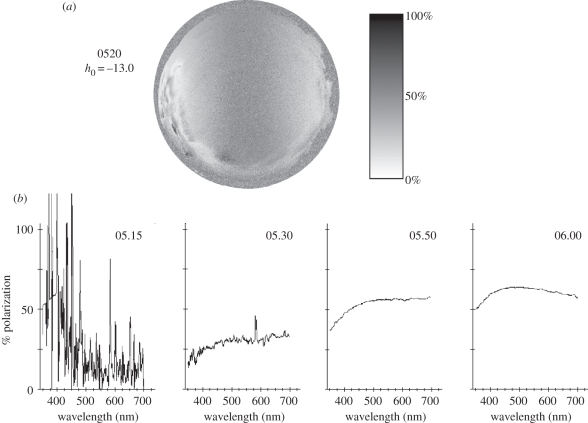
Skylight polarization during morning twilight. These data were collected at the same location as those of figure 2. (a) The polarization pattern at 5.20 h, when the Sun was 13° below the horizon (h0). The key for the degree of polarization is at the right, with the analysis carried out as in figure 2. Predicted sunrise was at 06.10 h on this day, so the characteristic skylight polarization pattern is visible here almost 1 h before actual sunrise. (b) The spectrum of polarization measured at the zenith using a calibrated Ocean Optics QE65 000 spectrometer fitted with a 15° radiance-collecting head, 16 September 2007. Predicted sunrise was at 06.03 h, and measurements began at 04.15 h. Note that the characteristic skylight polarization spectrum was not measurable at 05.15 h, but that it is fully developed (though less than at sunrise) by 05.30 h. Polarization in the sky decreases at short wavelengths owing to multiple-path scattering.
The CSC1001 and CSC1002 each contain an internal turret with four or seven slots, respectively, that is designed to mount DIC condenser prisms and illumination masks. This feature makes these condensers ideal for use in brightfield and oblique illumination, Dodt contrast, and DIC imaging. Please see the table to the left for the slots available in each turret. Each slot can be rotated into the beam path using a knurled dial on the side of the condenser. Labels are included that can be attached to the dial to indicate which slot is currently in the optical path. As shown in the photo below, the turret's slots can be accessed by removing the top cover using a 5/64" (2 mm) hex key.
Consequently, spelling variations in names are frequently found in early Anglo-Saxon and later Anglo-Norman documents. One person's name was often spelled ...
Elliptical polarization

The condenser's numerical aperture (NA) strongly impacts a microscope's resolution, since the angular range of the light incident on the sample affects the angular range of light transmitted or reflected by the sample. According to a general rule for optimizing resolution, the condenser NA should be as least as large as the objective NA. In other words, the cone of light provided by the condenser should have an angular range that matches or exceeds that accepted by the objective lens.
Because underwater polarization originates locally by scattering, the observed degree of polarization in a scene varies strongly with the brightness of the background. Reflection of light by background objects is rarely strongly polarized (as it can be in air) because of the relatively greater refractive index of water, but even if it were polarized, the rapid attenuation of polarization state with distance removes the original signal at viewing distances of only a few metres. Thus, polarization tends to be relatively stronger against dark parts of an underwater scene (or from the water background) than bright regions, because most of the light reaching the viewer from these regions has been scattered by water itself. This is obvious in the example illustrated in figure 6, showing the appearance of an underwater reef scene photographed through horizontal, 45°, and vertical linear polarizers. From these images, the degree and angle of linear polarization can be computed and displayed for each pixel (figure 6, bottom panels). Note that in this scene, which is typical, polarization is close to horizontal throughout much of the field of view, although there are variations related to surface orientation of nearby objects (most of the blue and green spots are artefacts caused by wave ripple or fish motion between frames). Note that the degree of polarization correlates well with the background darkness and also that the open water region, on the right margin of the image, is evenly polarized with a uniformly horizontal axis.
Note: Thorlabs does not guarantee compatibility with other industry-standard microscopes not explicitly mentioned on this webpage.
In addition to the natural features of polarized-light distributions in scenes, animals themselves produce polarization signals (in some cases, circularly polarized ones), the study of which is still in its early phases. It is also possible that animals may manipulate polarized light in ways that decrease their visibility, creating ‘polarization camouflage’. While the importance of light's polarization for animals has been recognized for over half a century, recent research emphasizes how this property of light, of which humans are only dimly aware, plays many roles in biology. As is revealed by the papers throughout this special issue, our understanding of the roles that polarized light plays in the lives of animals continually evolves, and many questions concerning polarization vision, polarization signalling and the mechanisms by which living photoreceptors detect and analyse light's polarization remain unanswered—and sometimes, even unasked!.
Various modules are available for sample viewing and data collection. Trinoculars have three points of vision to view the sample directly as well as with a camera. Double camera ports redirect or split the optical path among two viewing channels. Camera tubes increase or decrease the image magnification. For data collection, Thorlabs offers both cameras and photomultiplier tubes (PMTs), the latter being necessary to detect fluorescence signals for confocal microscopy. Breadboard tops provide functionality for custom-designed data collection setups. Modules are attached to the microscope body via a circular dovetail (see the Microscope Dovetails tab or here for details).
Underwater images of polarization, taken at a site on the Great Barrier Reef, Australia, near the Lizard Island Research Station using a calibrated digital camera in a submersible housing fitted with a rotating linear polarizer. The top set of three images shows the raw images captured with the polarizer rotated to three positions, transmitting the e-vector indicated by the double-headed arrow in the upper right corner of each image. Note that the image with the polarizer horizontal is distinctly hazier than the image taken with the polarizer oriented vertically. The bottom panels show the data analysed for degree of polarization and angle of polarization (e-vector angle), plotted in false colour with the appropriate colour key to the right of each image. Note that polarization is generally greater against darker regions of the background, as well as in the open water view on the right margin of the image. The angle of polarization is near horizontal throughout the image, with some small variations visible on the substrate owing to reflection (although the reflected polarization is very weak). Small patches of random colour in the analysed images are owing to motions of the water's surface or to movements of fishes swimming over the reef.
Aperture Stop DiaphragmEach condenser is equipped with an adjustable aperture stop diaphragm that is controlled by a lever on the side. For the brightest illumination, the condenser's NA should be equal to or slightly smaller than that of the highest-NA objective that will be used with the microscope. By opening and closing the diaphragm, the effective numerical aperture (NA) of the condenser can be adjusted, allowing it to match the NA of the objective. Note that closing the diaphragm will reduce the illumination intensity.
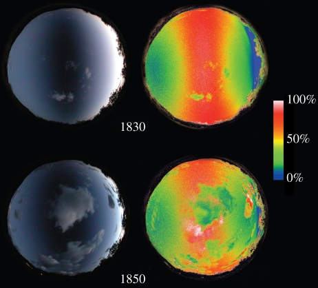
Polarization visible in the sky at sunset. These images were obtained using a calibrated digital camera fitted with a 180° ‘fisheye’ lens, aimed at the zenith, and with a linear polarizer placed behind the lens. In each image, north is to the top and east is to the left. Two examples are illustrated, with the raw image captured with the polarizer oriented east/west shown on the left. Since the polarization band passing through the zenith is polarized perpendicular to the Sun's position below the horizon in the west, the dark band shows polarization with the e-vector oriented north/south. Analysed images for the degree of polarization are illustrated on the right (the key for the analysed, false-colour image is provided on the far right). Actual sunset was at 18.14 h at this location on this day (15 September 2004; Lizard Island, Queensland, Australia). Note that the polarization pattern remained stable until well after sunset, and that the presence of clouds locally depolarizes the skylight.
A multi-element microscopy system can be aligned to provide Köhler (Koehler) illumination, in which the light collected from a light source like a lamp or light emitting diode (LED) is imaged differently than the light collected from the sample. The light source is intentionally never imaged to the sample (object) plane or to the camera sensor. The sample plane is instead uniformly illuminated, typically over the broad range of angles required for high-resolution imaging. As a result, Köhler illumination prevents superimposing an image of the lamp or LED structure onto the camera sensor.
Various sample and equipment mounting options are available to take advantage of the large working space of this microscope system. Large samples and ancillary equipment can be mounted via mounting platforms, which fit around the microscope body and utilize a breadboard design with regularly spaced tapped through holes. Small samples can be mounted on rigid stands (for example, see the purple component to the right), which have holders for different methods of sample preparation and data collection, such as slides, well plates, and petri dishes. For more traditional sample mounting, slides can also be mounted directly onto the microscope body via a manual XY stage. The rigid stands can translate by way of motorized stages (sold separately), while the mounting platforms contain built-in mechanics for motorized or manual translation. Rigid stands can also be mounted on top of the mounting platforms for independent and synchronized movement of multiple instruments, if you are interested in performing experiments simultaneously during microscopy.
Once illuminated, examining a sample with a microscope requires both focusing on the sample plane (see blue components to the right) and visualizing the resulting image (see pink components).
Figure 2: In epi-illumination microscopes, the objective provides the light that illuminates the sample. It also collects the light reflected and scattered from the sample. Due to this, and in contrast to the case illustrated in Figure 1, both the illumination and imaging angles depend only on the objective.
Close inspection of the images in the top row of figure 6 reveals subtle differences in contrast and clarity. In particular, since most underwater scatter creates polarization that is near horizontal in orientation, images taken using a horizontal polarizer are notably hazier than images using a vertically oriented filter. This simple means of image enhancement can extend visual range and object detection in water by at least 20 per cent and up to 80 per cent [21,22], a fact that has been discovered by some midwater predators that use polarization vision to detect prey [23,24]. The significant, if marginal, gains available simply by using polarization filters have encouraged more complex instrumental or computational approaches to enhancing underwater vision and image quality ([25–28]; see also [29]). Several techniques have taken advantage of the natural polarization properties of underwater light, following the observation that the polarization originates in water, and that submerged objects reflect relatively little polarized light, especially when viewed from some distance away.
The 2D CCD detector is a state of the art analogue detection system for ARPES and imaging applications. It features a highly sensitive 2D CCD camera for data ...
Köhler Illumination: A method of illumination that utilizes various optical elements to defocus and flatten the intensity of light across the field of view in the sample plane. A condenser and light collimator are necessary for this technique.
The image of the source at the aperture stop provides light to the condenser lens, which transmits the light as bundles of parallel rays. Each bundle of rays originates from a unique point on the source image. The angle at which a particular bundle of rays is incident on the sample plane is larger when the source point is displaced farther from the optical axis. In other words, closing the aperture stop would reduce the range of illumination angles, as well as the illumination intensity at the sample plane.


 Ms.Cici
 8618319014500