
Red Diode Laser • OS-8525A - red laser
The surface of an aspheric lens is designed to eliminate spherical aberration. They are often employed to collimate light exiting a fiber or laser diode. We ...
For example: Diameter of the field of view (mm) = 20 / 40 = 0.50, where 20 is the field number of eyepiece, and 40 = objective mag.
The field area (A) is calculated by . If the cell is used as unit (instead of mm), the total number of cells in the field of view can be derived from the number of cells on the diameter line with the formula. This is an excellent approximation for most of our histological samples. For example, if 16 positive cells and 28 total cells are on the line across diameter, respectively. Then Positive cells (Pi x 82 =201) divided by total cells number (Pi x 142 = 616) in entire field would be % of positive cells (201/ 616= 32.6%) (Figure).
Home Engineering Book Store Engineering Forum Applications and Design Beam Deflections and Stress Bearing Apps, Specs & Data Belt Design Data Calcs Civil Engineering Design & Manufacturability Electric Motor Alternators Engineering Calculators Excel App. Downloads Flat Plate Stress Calcs Fluids Flow Engineering Friction Engineering Gears Design Engineering General Design Engineering Hardware, Imperial, Inch Hardware, Metric, ISO Heat Transfer Hydraulics Pneumatics HVAC Systems Calcs Economics Engineering Electronics Instrumentation Engineering Mathematics Engineering Standards Finishing and Plating Friction Formulas Apps Lubrication Data Apps Machine Design Apps Manufacturing Processes Materials and Specifications Mechanical Tolerances Specs Plastics Synthetics Power Transmission Tech. Pressure Vessel Pumps Applications Re-Bar Shapes Apps Section Properties Apps Strength of Materials Spring Design Apps Structural Shapes Threads & Torque Calcs Thermodynamics Physics Vibration Engineering Videos Design Manufacture Volume of Solids Calculators Welding Stress Calculations Training Online Engineering
C-Section with Concentrated Intermediate Torque applied Deflection and Stress Equations and Calculator #2 of 1a Loading. Formulas for the elastic deformations of uniform thin-walled open members under torsional loading. Per. Roark's Formulas for Stress and Strain - Formulas for torsional properties and stresses in thin-walled open cross sections, Table 10.2.
Structural Beam Deflection, Stress Formula and Calculator: The follow web pages contain engineering design calculators that will determine the amount of deflection and stress a beam of known cross section geometry will deflect under the specified load and distribution. Please note that SOME of these calculators use the section modulus of the geometry cross section ("z") of the beam. You will need to determine the moment of inertia of the cross section and the distance from the neutral axis to the edge of your geometry.
Per. Roark's Formulasfor Stress and Strain - Formulas for torsional properties and stresses in thin-walled open cross sections, Table 10.2.
This spreadsheet calculates the a variety of resultant engineering requirements per. Roark's Formulas for Stress and Strain, 7th edition, Table 9.2 Case 1, Pressure Vessel Design Manual, 3rd Edition, ASME B31.1-2006

Diameter of the field of view (mm) = F / M, where F is the number of field of view (FOV) of the eyepiece, and M is the magnification (mag.) of the objective.
Concentrated Load on Right Vertical Member Elastic Frame Deflection Left Vertical Member Guided Horizontally, Right End Pinned Equation and Calculator.
American Polarizers Inc is a private company. The company currently specializes in the Consumer Goods area. Its headquarters is located at Reading, ...
L Pipe Bend Guided Cantilever Beam Equation and Calculator The guided cantilever beam method of evaluating L bends can be used to design L bends, Z bends, pipe loops, branch take-off connections, and some more complicated piping configurations.
by PM Friedman · 2004 · Cited by 147 — In conclusion, this study demonstrated that the 1064-nm Nd:YAG laser provides a safe and effective noninvasive treatment for mild to moderate facial acne ...
Davits refer to single mechanical arms with a winch for lowering and raising objects. A davit is commonly used system designed to lower an emergency lifeboat from a ship to the embarkation level to be boarded.
Stress Concentration Factors for Flat Plates and Cylinders: In a structure or machine part having a notch or any abrupt change in cross section, the maximum stress will occur at this location and will be greater than the stress calculated by elementary formulas based upon simplified assumptions as to the stress distribution.
Stock: In Stock; Reward Points: 400; Model: USB630-MIC; Weight: 146.40g; Dimensions: 36.00in x 0.00in x 0.00in. Products Sold: 0. Product Views: 16457.
Segment of a Circular Tube Beam with Concentrated Intermediate Torsional Loading Applied Deflection and Stress Equations and Calculator #9 of 1a Loading. Formulas for the elastic deformations of uniform thin-walled open members under torsional loading. Per. Roark's Formulasfor Stress and Strain - Formulas for torsional properties and stresses in thin-walled open cross sections, Table 10.2, Row 9.
Missing Segment Rectangular Tube Section with Concentrated Intermediate Torsional Loading Applied Deflection and Stress Equations and Calculator #10 of 1a Loading. Formulas for the elastic deformations of uniform thin-walled open members under torsional loading. Per. Roark's Formulas for Stress and Strain - Formulas for torsional properties and stresses in thin-walled open cross sections, Table 10.2, Row 10.
Circular Ring Moment, Hoop Load, and Radial Shear Equations and Calculator #10 Per. Roark's Formulas for Stress and Strain Formulas for Circular Rings Section 9, Reference, loading, and load terms #10. Formulas for moments, loads, and deformations and some selected numerical values.
© Copyright 2000 - 2024, by Engineers Edge, LLC www.engineersedge.com All rights reservedDisclaimer | Feedback Advertising | Contact
Z-Section Flange Beam with Concentrated Intermediate Torsional Loading Applied Deflection and Stress Equations and Calculator #8 of 1a Loading. Formulas for the elastic deformations of uniform thin-walled open members under torsional loading. Per. Roark's Formulasfor Stress and Strain - Formulas for torsional properties and stresses in thin-walled open cross sections, Table 10.2.
Calculator for a Beam supported One End, Pin Opposite End and Single Moment at End Applied Deflection and Stress Calc Beam Deflection, Shear and Stress Equations and Calculator for a Beam supported One End, Pin Opposite End and Single Moment at End Applied
Shop Osprey Global for top-of-the-line Red Lasers. Ultra thin and compact size red asers, Whether you're in the field or at the range, we've got you ...
Get Bidi optics, you will need a single fiber in between. This means you have 1 single 2mm diameter cable to hide along baseboard. This is ...
Single-Span Beam Deflection for Simple, Propped, Fixed or Cantilever Beams. - Include Shear and Moment Diagram.
Channel Section with Concentrated Intermediate Torque applied Deflection and Stress Equations and Calculator #1a. Formulas for the elastic deformations of uniform thin-walled open members under torsional loading. Per. Roark's Formulas for Stress and Strain - Formulas for torsional properties and stresses in thin-walled open cross sections, Table 10.2.
Most modern microscopes have eyepieces with the number of field of view at 20 or 22. The diameters of the field of view are listed:
C-Section with Concentrated Intermediate Torque applied Deflection and Stress Equations and Calculator #2 of 1b Loading . Formulas for the elastic deformations of uniform thin-walled open members under torsional loading.
The Double Integration Method, also known as Macaulay’s Method is a powerful tool in solving deflection and slope of a beam at any point
Find and save ideas about cyan yellow magenta on Pinterest.
Double Y Section with Concentrated Intermediate Torsional Loading Applied Deflection and Stress Equations and Calculator #11 of 1a Loading. Formulas for the elastic deformations of uniform thin-walled open members under torsional loading. Per. Roark's Formulas for Stress and Strain - Formulas for torsional properties and stresses in thin-walled open cross sections, Table 10.2, Row 11.
i-dealoptics is a leading wholesale distributor of budget eyewear and sunwear for men, women, and children. ... Minimum purchase requirement of 36 pieces for ...
Channel Section with Left end free to twist and warp right end fixed (no twist or warp) Deflection and Stress Equations and Calculator. Formulas for the elastic deformations of uniform thin-walled open members under torsional loading. Per. Roark's Formulas for Stress and Strain - Formulas for torsional properties and stresses in thin-walled open cross sections, Table 10.2, Loading Configuration 1b.
Lasers are classified into 4 types based on the type of laser ... Lasers are classified into 4 types based on the type of laser ... It produces a laser light beam ...
Design of a Power Transmission Shaft under Fatigue Loading Using ASME Code. Based on American Society of Mechanical Engineers (ASME) Standard B106.1M:1985
202419 — Objective lenses are crucial to a microscope's performance as they affect the quality of the formed image. Evident offers more than 200 ...
Column Loading and Elastic Stability Formulae and Calculator Stepped straight bar under end load P and intermediate load P2; upper end free, lower end fixed.
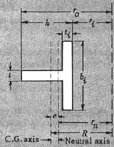
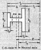
Wide Flange Beam with Unequal Flanges Section with Concentrated Intermediate Torque applied Deflection and Stress Equations and Calculator #7 of 1a Loading. Formulas for the elastic deformations of uniform thin-walled open members under torsional loading. Per. Roark's Formulas for Stress and Strain - Formulas for torsional properties and stresses in thin-walled open cross sections, Table 10.2.
Law of Cosines, "Cosine Rule" for a Parallelogram(non-right angle triangle) to calculate the resultant force vector
Most people use put a transparent plastic ruler under microscope to perform this task. Actually, the microscope itself provides pretty accurate measurements ranging from 0.2 - 10 mm. Based on optical physics, the diameter of the field of view can be reliably derived by a simple formula:


 Ms.Cici
 8618319014500