
Randomizing phase to remove acousto-optic device wiggle ... - acousto-electric tweezer
Field size and focal length are linear in field of view (half of sensor dimension or twice the focal length both produce half the field dimension). But the angle is a tangent function, which is Not straight-line linear (the angle is approximately linear if angle is not more than about 10 degrees (called the Small-Angle Approximation).
Back to the general ideas, of all above: This Distance to Field doesn't necessarily mean to subject or to focus point. Here it means the distance to the point where you want field size calculated (perhaps the background, computing what will show in the picture). As noted, use either meters or feet (the units all cancel out). And/or substitute width for height if appropriate. Just be consistent, and solve for the unknown. FWIW, cameras report focus distance as s, measured to the sensor surface. Lens calculations however compute with distance d, in front of the lens node (which except for telephoto lenses, is normally inside the lens body). The Thin Lens Equations use the distance d in front of the lens node, but the lens specifications are "focused distance" (marked s in the diagram) which is to the sensor plane. Working Distance = d = S1 (distance in front of lens) Focal Length = f = S2 (distance behind lens) Focus Distance = d + f (subject distance to the sensor plane) The Thin Lens Model simplifies, and is practical and adequate for most computing, even if this model has one glass element and one central node point. Camera lenses have multiple glass elements, and are "thick lenses", much more complex, and have two node points, often called H for the field view side node, and H' for the sensor view side node. These two nodes might be designed a few inches apart, but they necessarily still see the same angle. The actual node position normally only matters to us for close macro distances, or perhaps in efforts to correct panoramic parallax. Sensor focal plane marking ϴ This front node is often a point inside the lens, perhaps crudely assumed about the middle of the lens (but it does move with zoom), but it is small and can often be ignored. Lens specifications normally instead measure field focus distance from the sensor, so you could subtract a few inches from your subject distance (to be at that node) to compute Field of View, but normally this is not significant except at extremely close focus and macro distances. It is more significant for macro distances. Example, the Nikon 105mm f/2.8 VR macro lens has specification "Minimum focus distance: 31.4 cm (1.03 feet), which is measured to the sensor plane at rear of the camera top. There's a small measuring symbol on top of the camera there, an O with a line through it (shown on this Nikon DSLR, or is often on the side of the pentaprism dome) to mark the sensor focal plane location. But at 1:1, a reliable chart of macro lens working distances says that 105 mm lens has a Working Distance (in front of lens) at 1:1, which is significantly less, 14.8 cm (5.8 inches), which differs by 16.6 mm due to the length of the lens and thickness of the camera body. SO NOTE: the terms Focal Length and lens focus distance are measured to the sensor plane, to that mark just mentioned. But Field of View and Depth of Field are computed to a node inside or near the lens. However, the Field of View calculator and the Depth of Field calculators instead are designed around the Thin Lens Model, and are measured to a node point inside a "Normal" lens, perhaps near its middle. So calculated distances are measured to the designed focal nodes. We are rarely told where the nodes are designed, often both are inside the lens body somewhere, but some are outside. For telephoto lenses, the rear node H' (focal length from sensor plane) is instead designed just outside the front lens element, and its field H node is the focal length dimension approximately in front of the front lens surface (see an example). The designer's term "telephoto" is about this reposition of the nodal point so that the physical lens is NOT longer than its focal length. And in wide angle lenses for DSLR, the rear node H' is generally designed behind the rear lens surface, at least for SLR (lens is moved well forward to provide room to allow the larger SLR mirror to rise... 12 mm lens but 24 mm mirror, etc). This difference is only a few inches, but it affects where the focused distance is measured to the sensor. And it shifts a bit as the lens is focused much closer. Repeating, the focal length marked on the lens is specified for when focus at infinity, and focal length is longer when focused closer. But the "Subject Distance" (S in diagram) is measured to the sensor focal plane (it is the "focus distance"), where we see a small line symbol like ϴ marked on the top of the camera (often near top LCD on right side, but some are on left side of camera). The line across the circle indicates the location of the film or sensor plane (for focus measurements). However, the Thin Lens Equation uses the working distance d in front of the lens. This is why we often see in equations: (S - f) used for d. Again, three points. Simple cameras typically do not give specifications about the sensor size in mm (the 1/xx inch number is near meaningless dimensionally). However crop factor might be determined, and can compute sensor size. The focal length is a nominal number, rounded, not precisely exact. And the marked focal length applies at infinity, and it will be a little different if focused close, so the focus distance should not be too close, at least a meter or two. Normally lenses won't focus close enough to matter much (except macro lenses). Camcorder 16:9 fits the full view circle from the lens. But 16:9 video on a 3:2 or 4:3 camera sensor (or a 4:3 image from a 16:9 camcorder) is cropped and resampled, instead of fitting the lens full view circle. The Field of View calculator handles that, always with the assumption that the maximum possible area of the sensor is always used. Some cameras make exceptions to that, unknown to me. Or if you know, you can specify the exact size of the sensor used. For Macro, computing Field size from magnification is more convenient than from focal length, since we don't really know focal length at macro extension. The math above WILL BE INACCURATE at macro distances, because the Focal Length has changed there. For example, we do know the Thin Lens Formula specifies focal length at 1:1 is extended to 2x the marked focal length at infinity. So FWIW, for the calculator Option 8 for magnification 1 (1:1) for a 50 mm lens at 2x, we could enter it as 100 mm, and compute field width for a full frame sensor as 0.11811 feet (which x12 and x25.4 is the expected 36 mm full frame width for 1:1). Subject distance becomes 0.32808 feet (both are feet if we use feet), which x12 is 3.9 inches. But this distance is measured to the Principle Point typically inside the lens somewhere, which we really don't know where that is, and it becomes very significant for macro. Which is why field of view for macro is instead computed from magnification (reproduction ratio, like 1:1). Focal length and subject distance determine Magnification, which is the ratio of size of image to size of actual subject. Or the ratio of size of sensor to the size of the remote field. We could compute for magnification here, but we likely don't know new focal length at that close magnification. Just using magnification has more significance up closer (easier for macro), which is where our knowledge of the actual focal length is weakest. We could measure the field to compute the actual magnification. However Magnification is simply: m = s2/s1. Or m = f/d. Or m = f/(S-f). Other macro ideas: Actual focal length = Sensor dimension × Working distance / Field dimension Those are all in the same units. Note that working dimension is to the lenses internal node, and NOT just to the front of the lens. Which is probably only an inch or two difference, but it becomes very significant at macro distances. Field dimension = Sensor dimension / Magnification Let's say it this way: 1:1 macro, the focal length f is same as the distance d in front of lens (each with its own node). 1:1 macro (magnification 1), the field of view is exactly the same size as the sensor. 1:2 macro (magnification 0.5), the field of view is twice the size of the sensor. 1:4 macro (magnification 0.25), the field of view is four times the size of the sensor. This is true of any focal length for any lens (or method) that can achieve the magnification. Focal length and subject distance are obviously the factors determining magnification (it is still about them), but magnification ratio is simply easier work for macro. The easiest method to determine field of view for macro is to simply put a mm ruler in the field. If a 24 mm sensor width sees 32 mm of ruler, then that is the field of view, and the magnification is 24/32 = 0.75 (this scale of magnification is 1 at 1:1, and is 0 at infinity). The definition of macro 1:1 magnification is that the focal length and subject distance are equal (distances in front of and behind the lens nodes are necessarily equal, creating 1:1 magnification). In this Thin Lens Equation, if s1 and s2 are equal, the formula is then 2/s1 = 1/f, or 2f = s1. So lens extension to 2f gives 1:1. And since f/stop number = f / diameter, then if 2f, then f/stop number is 2x too, which a double f/stop number is 2 stops change, which is the aperture loss at 1:1. We know those things, this is just why. But the point here, if f is actually 2f at 1:1 macro, the field of view changes with it. None of the FOV calculators are for macro situations (too close, magnification is instead the rule there). Field of View calculators expect subject distance to be at least a meter or so, reducing the focal length error to be insignificant. Menu of the other Photo and Flash pages here
Lumens and LUX measurements only pertain to visible light. So this suits the regular flashlight industry and their users can happily converse with one another all day long. But UV is light which does not fall into the visible spectrum. So the UV industry to describe the attributes of their light sources cannot use terms such as lumens or LUX. This is only used as a measure of the light observed.
Field angle of view = 2 x arctan ((sensor dimension (mm) / 2) / focal length (mm)) 2 × arctan( Sensor Width mm 2 × Focal Length mm ) = Degrees
4. Complete User Manual - downloadable from our website. This covers most if not all issues and procedures, including any further questions you may have
In this equation, we can see that if the subject at s1 is at infinity, then 1/s1 is zero, so then s2 = f. This is the marked focal length that applies when focused at infinity. What camera lenses call the focused distance is s = s1 + s2, from subject to the sensor plane. Also if at 1:1 magnification (equal image size on both sides of lens), then s1 = s2, saying that the working macro distance in front of the lens node (extended at 1:1) is equal to the distance to the sensor image plane (both sides at 2x focal length). This makes f/stop number be 2x, which is 2 EV light loss. Those are basics. Internal focusing macro lenses can slightly reduce this light loss, but it is still near 2 EV. The Math Sensor dimension / 2focal length = Field dimension / 2distance This diagram is the basis of Field of View and Depth of Field calculations. The half angles form geometry's Similar Triangles from the equal angles on each side of the lens. The /2 cancels out on both sides. This equation simply says that the equal angles have the same trigonometry tangent (opposite / adjacent) on each side of lens (but the /2 must be included then). The lens is simply an enlargement device (actually a size reduction) proportionally to the ratio of focal length / field distance. But be aware that focal length lengthens with closer focus distance (and is generally unknown then (focal length is 2x at 1:1 magnification, but lens internal focusing can make changes). Focusing and zooms and especially internal focusing change focal length internally. The focal length marked on the lens is at infinity focus. Focal length is generally near close enough at the closest focus of a regular lens, but calculations will be more accurate if focus is out a bit further. But macro work uses Magnification instead of subject distance. This Thin Lens Model simplifies, as if it were a simple one glass element (like a handheld magnifying lens) with only the one central node point. Multi-element âThickâ camera lenses have two nodes for each side of lens (see the fstop page). But camera lenses normally have several (to many) glass lens elements (a thick lens), designed to correct optical aberrations and distortions, and also to zoom. The Thin Lens Model does still work well for practical computing purposes, at least at distances of at least maybe a meter or two, making a few mm dimension to the node be less important (a bit more description below). The focal length is measured from the sensor plane to the lens node H' (often inside the lens, but not always). Technically, the focal length Marked on the lens applies when focused at infinity, but it will be a bit longer when focused closer. Lens equations use distance d in front of the field node, however note that specifications of lens focus-distance (like minimum closest focus) specify s to the sensor, the sum of d and f. The standard camera magnification geometry uses the standard ratios of the similar triangles shown above. The field dimension angle in front of this lens node is the same angle (opposite angles) as the sensor dimension angle behind the lens. The ratio of distances on each side of the lens are the same as the ratio of the size dimensions on each side of the lens. These ratios (as shown first below) are simply the trigonometry tangents of the same angle on each side of the lens (tangent is opposite side over adjacent side). In this equation, rearrangement will compute any one term from the other three. But one mm of error in focal length or sensor size is magnified in the field, so input accuracy is critical. The math is simple, but the difficult part of computing this will be to first accurately determine the correct sensor dimensions, and/or the zoom lens focal length (small errors get magnified at the larger distant field). Trigonometry does also work for this, but we don't need trig except to compute the actual angles of Field of View. Because Field of View dimensions are just similar triangles (shown gray above). The three field or sensor dimensions are Height, Width, or Diagonal, each are computed individually. Using the (opposite dimension / 2) to create right angles for trig, these ratios are the trig tangent of the half angles, which is the same opposite angle on both sides of lens (the two formula ratios are necessarily equal). The /2 cancels out on both sides, and any unit conversions to feet or meters on the right side cancel out. It becomes a very simple equation. Do be consistent with units, but then there is no conversion of units needed (same ratio on both sides). Basics of lens optics in all of these equations(similar triangles on both sides of the lens)
This is magnification on the sensor or film. The image must still be enlarged for viewing.1:1 macro reproduction at 1× is when these two top and bottom values are equal.Distant object size is reduced greatly, like perhaps maybe magnification of 0.001x or less.
The Math Sensor dimension / 2focal length = Field dimension / 2distance This diagram is the basis of Field of View and Depth of Field calculations. The half angles form geometry's Similar Triangles from the equal angles on each side of the lens. The /2 cancels out on both sides. This equation simply says that the equal angles have the same trigonometry tangent (opposite / adjacent) on each side of lens (but the /2 must be included then). The lens is simply an enlargement device (actually a size reduction) proportionally to the ratio of focal length / field distance. But be aware that focal length lengthens with closer focus distance (and is generally unknown then (focal length is 2x at 1:1 magnification, but lens internal focusing can make changes). Focusing and zooms and especially internal focusing change focal length internally. The focal length marked on the lens is at infinity focus. Focal length is generally near close enough at the closest focus of a regular lens, but calculations will be more accurate if focus is out a bit further. But macro work uses Magnification instead of subject distance. This Thin Lens Model simplifies, as if it were a simple one glass element (like a handheld magnifying lens) with only the one central node point. Multi-element âThickâ camera lenses have two nodes for each side of lens (see the fstop page). But camera lenses normally have several (to many) glass lens elements (a thick lens), designed to correct optical aberrations and distortions, and also to zoom. The Thin Lens Model does still work well for practical computing purposes, at least at distances of at least maybe a meter or two, making a few mm dimension to the node be less important (a bit more description below). The focal length is measured from the sensor plane to the lens node H' (often inside the lens, but not always). Technically, the focal length Marked on the lens applies when focused at infinity, but it will be a bit longer when focused closer. Lens equations use distance d in front of the field node, however note that specifications of lens focus-distance (like minimum closest focus) specify s to the sensor, the sum of d and f. The standard camera magnification geometry uses the standard ratios of the similar triangles shown above. The field dimension angle in front of this lens node is the same angle (opposite angles) as the sensor dimension angle behind the lens. The ratio of distances on each side of the lens are the same as the ratio of the size dimensions on each side of the lens. These ratios (as shown first below) are simply the trigonometry tangents of the same angle on each side of the lens (tangent is opposite side over adjacent side). In this equation, rearrangement will compute any one term from the other three. But one mm of error in focal length or sensor size is magnified in the field, so input accuracy is critical. The math is simple, but the difficult part of computing this will be to first accurately determine the correct sensor dimensions, and/or the zoom lens focal length (small errors get magnified at the larger distant field). Trigonometry does also work for this, but we don't need trig except to compute the actual angles of Field of View. Because Field of View dimensions are just similar triangles (shown gray above). The three field or sensor dimensions are Height, Width, or Diagonal, each are computed individually. Using the (opposite dimension / 2) to create right angles for trig, these ratios are the trig tangent of the half angles, which is the same opposite angle on both sides of lens (the two formula ratios are necessarily equal). The /2 cancels out on both sides, and any unit conversions to feet or meters on the right side cancel out. It becomes a very simple equation. Do be consistent with units, but then there is no conversion of units needed (same ratio on both sides). Basics of lens optics in all of these equations(similar triangles on both sides of the lens)
Back to the general ideas, of all above: This Distance to Field doesn't necessarily mean to subject or to focus point. Here it means the distance to the point where you want field size calculated (perhaps the background, computing what will show in the picture). As noted, use either meters or feet (the units all cancel out). And/or substitute width for height if appropriate. Just be consistent, and solve for the unknown. FWIW, cameras report focus distance as s, measured to the sensor surface. Lens calculations however compute with distance d, in front of the lens node (which except for telephoto lenses, is normally inside the lens body). The Thin Lens Equations use the distance d in front of the lens node, but the lens specifications are "focused distance" (marked s in the diagram) which is to the sensor plane. Working Distance = d = S1 (distance in front of lens) Focal Length = f = S2 (distance behind lens) Focus Distance = d + f (subject distance to the sensor plane) The Thin Lens Model simplifies, and is practical and adequate for most computing, even if this model has one glass element and one central node point. Camera lenses have multiple glass elements, and are "thick lenses", much more complex, and have two node points, often called H for the field view side node, and H' for the sensor view side node. These two nodes might be designed a few inches apart, but they necessarily still see the same angle. The actual node position normally only matters to us for close macro distances, or perhaps in efforts to correct panoramic parallax. Sensor focal plane marking ϴ This front node is often a point inside the lens, perhaps crudely assumed about the middle of the lens (but it does move with zoom), but it is small and can often be ignored. Lens specifications normally instead measure field focus distance from the sensor, so you could subtract a few inches from your subject distance (to be at that node) to compute Field of View, but normally this is not significant except at extremely close focus and macro distances. It is more significant for macro distances. Example, the Nikon 105mm f/2.8 VR macro lens has specification "Minimum focus distance: 31.4 cm (1.03 feet), which is measured to the sensor plane at rear of the camera top. There's a small measuring symbol on top of the camera there, an O with a line through it (shown on this Nikon DSLR, or is often on the side of the pentaprism dome) to mark the sensor focal plane location. But at 1:1, a reliable chart of macro lens working distances says that 105 mm lens has a Working Distance (in front of lens) at 1:1, which is significantly less, 14.8 cm (5.8 inches), which differs by 16.6 mm due to the length of the lens and thickness of the camera body. SO NOTE: the terms Focal Length and lens focus distance are measured to the sensor plane, to that mark just mentioned. But Field of View and Depth of Field are computed to a node inside or near the lens. However, the Field of View calculator and the Depth of Field calculators instead are designed around the Thin Lens Model, and are measured to a node point inside a "Normal" lens, perhaps near its middle. So calculated distances are measured to the designed focal nodes. We are rarely told where the nodes are designed, often both are inside the lens body somewhere, but some are outside. For telephoto lenses, the rear node H' (focal length from sensor plane) is instead designed just outside the front lens element, and its field H node is the focal length dimension approximately in front of the front lens surface (see an example). The designer's term "telephoto" is about this reposition of the nodal point so that the physical lens is NOT longer than its focal length. And in wide angle lenses for DSLR, the rear node H' is generally designed behind the rear lens surface, at least for SLR (lens is moved well forward to provide room to allow the larger SLR mirror to rise... 12 mm lens but 24 mm mirror, etc). This difference is only a few inches, but it affects where the focused distance is measured to the sensor. And it shifts a bit as the lens is focused much closer. Repeating, the focal length marked on the lens is specified for when focus at infinity, and focal length is longer when focused closer. But the "Subject Distance" (S in diagram) is measured to the sensor focal plane (it is the "focus distance"), where we see a small line symbol like ϴ marked on the top of the camera (often near top LCD on right side, but some are on left side of camera). The line across the circle indicates the location of the film or sensor plane (for focus measurements). However, the Thin Lens Equation uses the working distance d in front of the lens. This is why we often see in equations: (S - f) used for d. Again, three points. Simple cameras typically do not give specifications about the sensor size in mm (the 1/xx inch number is near meaningless dimensionally). However crop factor might be determined, and can compute sensor size. The focal length is a nominal number, rounded, not precisely exact. And the marked focal length applies at infinity, and it will be a little different if focused close, so the focus distance should not be too close, at least a meter or two. Normally lenses won't focus close enough to matter much (except macro lenses). Camcorder 16:9 fits the full view circle from the lens. But 16:9 video on a 3:2 or 4:3 camera sensor (or a 4:3 image from a 16:9 camcorder) is cropped and resampled, instead of fitting the lens full view circle. The Field of View calculator handles that, always with the assumption that the maximum possible area of the sensor is always used. Some cameras make exceptions to that, unknown to me. Or if you know, you can specify the exact size of the sensor used. For Macro, computing Field size from magnification is more convenient than from focal length, since we don't really know focal length at macro extension. The math above WILL BE INACCURATE at macro distances, because the Focal Length has changed there. For example, we do know the Thin Lens Formula specifies focal length at 1:1 is extended to 2x the marked focal length at infinity. So FWIW, for the calculator Option 8 for magnification 1 (1:1) for a 50 mm lens at 2x, we could enter it as 100 mm, and compute field width for a full frame sensor as 0.11811 feet (which x12 and x25.4 is the expected 36 mm full frame width for 1:1). Subject distance becomes 0.32808 feet (both are feet if we use feet), which x12 is 3.9 inches. But this distance is measured to the Principle Point typically inside the lens somewhere, which we really don't know where that is, and it becomes very significant for macro. Which is why field of view for macro is instead computed from magnification (reproduction ratio, like 1:1). Focal length and subject distance determine Magnification, which is the ratio of size of image to size of actual subject. Or the ratio of size of sensor to the size of the remote field. We could compute for magnification here, but we likely don't know new focal length at that close magnification. Just using magnification has more significance up closer (easier for macro), which is where our knowledge of the actual focal length is weakest. We could measure the field to compute the actual magnification. However Magnification is simply: m = s2/s1. Or m = f/d. Or m = f/(S-f). Other macro ideas: Actual focal length = Sensor dimension × Working distance / Field dimension Those are all in the same units. Note that working dimension is to the lenses internal node, and NOT just to the front of the lens. Which is probably only an inch or two difference, but it becomes very significant at macro distances. Field dimension = Sensor dimension / Magnification Let's say it this way: 1:1 macro, the focal length f is same as the distance d in front of lens (each with its own node). 1:1 macro (magnification 1), the field of view is exactly the same size as the sensor. 1:2 macro (magnification 0.5), the field of view is twice the size of the sensor. 1:4 macro (magnification 0.25), the field of view is four times the size of the sensor. This is true of any focal length for any lens (or method) that can achieve the magnification. Focal length and subject distance are obviously the factors determining magnification (it is still about them), but magnification ratio is simply easier work for macro. The easiest method to determine field of view for macro is to simply put a mm ruler in the field. If a 24 mm sensor width sees 32 mm of ruler, then that is the field of view, and the magnification is 24/32 = 0.75 (this scale of magnification is 1 at 1:1, and is 0 at infinity). The definition of macro 1:1 magnification is that the focal length and subject distance are equal (distances in front of and behind the lens nodes are necessarily equal, creating 1:1 magnification). In this Thin Lens Equation, if s1 and s2 are equal, the formula is then 2/s1 = 1/f, or 2f = s1. So lens extension to 2f gives 1:1. And since f/stop number = f / diameter, then if 2f, then f/stop number is 2x too, which a double f/stop number is 2 stops change, which is the aperture loss at 1:1. We know those things, this is just why. But the point here, if f is actually 2f at 1:1 macro, the field of view changes with it. None of the FOV calculators are for macro situations (too close, magnification is instead the rule there). Field of View calculators expect subject distance to be at least a meter or so, reducing the focal length error to be insignificant. Menu of the other Photo and Flash pages here
(2) Ready out-of-the -box. What's more we're taking the hassle away from you having to get and also pay extra for the extra bits-n-pieces to operate a rechargeable li-ion UV flashlight. At an inclusive price - no sneaky "you also need to purchase these" at check out! Your uvBeast V3 365nm MINI includes the accessories you need so it’s ready-to-use straight out of the box. It includes: a 21700 Lithium-ion 3.7 volt protected cell (4000mAh capacity) - you can also use a 18650 type (but it needs to be at least 67mm long); a USB-C cable; a mains USB plug (for mains supply power); and spare O-rings. Remember to remove the plastic battery insulation disc from within the battery compartment first, and to fit the positive end facing the LED head - full instructions are on the back of the packaging. Oh, and it's a DOUBLE-CLICK to turn on
Rearrange this ratio to compute desired unknown value. Examples: Distance to Object * = Real Object height * × Focal Length (mm) Object height on sensor (mm) Real Object height * = Distance to Object * × Object height on sensor (mm) Focal Length (mm) * feet or meters (but both same units) There are Other possible arrangements. But this next one must use Field dimension and Height converted to mm (304.8 mm per foot), because each ratio must be a dimensionless number. Magnification = Distance to Object (mm) Focal Length (mm) = Real Object height (mm) Object height on sensor (mm) This is magnification on the sensor or film. The image must still be enlarged for viewing.1:1 macro reproduction at 1× is when these two top and bottom values are equal.Distant object size is reduced greatly, like perhaps maybe magnification of 0.001x or less.
Now here comes the twist with ultraviolet light (or radiation to be more exact). Note: Don't freak out with that word radiation, because it is just describing the energy along the electromagnetic spectrum where visible light is also a type of radiation along with radio waves.
Field of viewcamera
So, coming back to what we just said - this light emits UV at 365nm wavelength. This means that the maximum density of the flux peaks at 365nm and the filter ensures this over other UV 365nm flashlights in the market.
Sign up to uvBeast.com for latest product updates, early bird access to new releases, invite-only offers and deals, and useful stuff not open to the general public
I was out hunting Yooperlites with a friend and a few couples showed up to do the same. They commented on how my light was brighter and lot up more minerals, and they were 100% correct! It blew their similarly sized blacklights in every way. Like always, I spread the word about the little and big UvBeast, as I have and both and love 'em!
At last, charging of the removable 21700 battery without the hassle of taking it out! Relief. Simply connect the supplied cable to the USB-C port to charge. That's it! You won’t need to lug around a separate charger!
This is a good question because it's often asked. But there are differences which apply to LEDs and UV lights in particular. And this is important to note for UV users.
Again, three points. Simple cameras typically do not give specifications about the sensor size in mm (the 1/xx inch number is near meaningless dimensionally). However crop factor might be determined, and can compute sensor size. The focal length is a nominal number, rounded, not precisely exact. And the marked focal length applies at infinity, and it will be a little different if focused close, so the focus distance should not be too close, at least a meter or two. Normally lenses won't focus close enough to matter much (except macro lenses). Camcorder 16:9 fits the full view circle from the lens. But 16:9 video on a 3:2 or 4:3 camera sensor (or a 4:3 image from a 16:9 camcorder) is cropped and resampled, instead of fitting the lens full view circle. The Field of View calculator handles that, always with the assumption that the maximum possible area of the sensor is always used. Some cameras make exceptions to that, unknown to me. Or if you know, you can specify the exact size of the sensor used.
In addition, UV is classified into longwave and shortwave. Longwave UV also known as UVA is not harmful to skin nor eyes. Longwave UV (UVA) is ~300nm and above, and so the V3 365nm flashlight emits longwave (UVA) UV light which is not dangerous. Shortwave UV however aka UVB and UVC, is harmful due to the shorter wavelength, and is ~300nm and below. This type of shortwave UV has the known ability to damage human DNA (cancerous), and so therefore is treated with extreme caution.
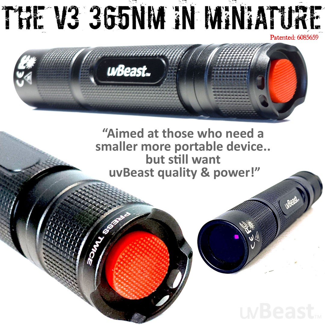
Prototyped & tested with demanding users like you. Then we put into production. Our R and D people are not asleep. We talk when we must and shut up and listen to feedback when we need to. We're always moving with innovation and new product developments. This time we enter the fray with size, portability, and convenience with as much optical uvBeast power we can muster. With user generated wish lists and rigorous user testing, you’re getting a proven and field tested product and avoiding a dud which nobody wants.
Ready for operation straight out-of-the-box. So avoid the hassle of extra shopping! We know that sourcing 21700 li-ion rechargeable button-top protected PCB cells designed for flashlights can be a hassle for some. So it's all included! Oh and it is 18650 compatible too.
Rearrange this ratio to compute desired unknown value. Examples: Distance to Object * = Real Object height * × Focal Length (mm) Object height on sensor (mm) Real Object height * = Distance to Object * × Object height on sensor (mm) Focal Length (mm) * feet or meters (but both same units) There are Other possible arrangements. But this next one must use Field dimension and Height converted to mm (304.8 mm per foot), because each ratio must be a dimensionless number. Magnification = Distance to Object (mm) Focal Length (mm) = Real Object height (mm) Object height on sensor (mm) This is magnification on the sensor or film. The image must still be enlarged for viewing.1:1 macro reproduction at 1× is when these two top and bottom values are equal.Distant object size is reduced greatly, like perhaps maybe magnification of 0.001x or less.
Let's say it this way: 1:1 macro, the focal length f is same as the distance d in front of lens (each with its own node). 1:1 macro (magnification 1), the field of view is exactly the same size as the sensor. 1:2 macro (magnification 0.5), the field of view is twice the size of the sensor. 1:4 macro (magnification 0.25), the field of view is four times the size of the sensor. This is true of any focal length for any lens (or method) that can achieve the magnification. Focal length and subject distance are obviously the factors determining magnification (it is still about them), but magnification ratio is simply easier work for macro. The easiest method to determine field of view for macro is to simply put a mm ruler in the field. If a 24 mm sensor width sees 32 mm of ruler, then that is the field of view, and the magnification is 24/32 = 0.75 (this scale of magnification is 1 at 1:1, and is 0 at infinity). The definition of macro 1:1 magnification is that the focal length and subject distance are equal (distances in front of and behind the lens nodes are necessarily equal, creating 1:1 magnification). In this Thin Lens Equation, if s1 and s2 are equal, the formula is then 2/s1 = 1/f, or 2f = s1. So lens extension to 2f gives 1:1. And since f/stop number = f / diameter, then if 2f, then f/stop number is 2x too, which a double f/stop number is 2 stops change, which is the aperture loss at 1:1. We know those things, this is just why. But the point here, if f is actually 2f at 1:1 macro, the field of view changes with it. None of the FOV calculators are for macro situations (too close, magnification is instead the rule there). Field of View calculators expect subject distance to be at least a meter or so, reducing the focal length error to be insignificant. Menu of the other Photo and Flash pages here
There is a Field of View Calculator here, but this page is about the math. There are approximations in calculations. The math is precise, but the data is less so. The required Focal length and Sensor Size are rounded specifications, losing a bit of precision. This little difference at the small sensor gets magnified in the field and scene. However, the results certainly are close enough to be very useful in any practical case. My experience is that the field is fairly accurate (at distances of at least a meter or so), assuming you actually know your parameters. Some problems are: You absolutely must know the actual correct sensor size in mm. Or the FOV calculator here can make a reasonable approximation of sensor size from the accurate Crop Factor. If not accurate, the field of view calculation will not be accurate. If you're guessing, your results will likely be troubled. Please see this summary of Issues determining Sensor Size which might help. You must know the actual correct lens focal length in mm. Zoom lens focal length is different at each and every zoom position. The image EXIF data may show focal length (but it is rounded in some degree). And of course just guessing about the field distance may be an approximation, or may not be at all accurate. Field of View calculators do NOT work for macro distances. Macro uses reproduction ration, like 1:1. Thin Lens Equation The Marked focal length of any lens is a rounded nominal number, like 50 or 60 mm. The actual can be a few percent different. Furthermore, the Marked focal length is only applicable to focus at infinity. Focal length normally increases when lens is extended forward to focus closer. Lens specs normally indicate this internal extension at closest focus distance. But internal focusing lenses can do internal tricks with focal length (some zooms and macro lenses can be shorter when up close, instead of longer). But generally speaking, focal length becomes a little longer at very close distances (2x longer at 1:1), so field of view could be a little smaller, but should be insignificant as long as magnification is greater than 0.1x, which in regular lenses is normally near their Minimum focus distance. But this calculation does not include macro distances. We are only seeking a ballpark FOV number anyway, we adjust small differences with our subject framing or cropping, but vague guesses about your distance and sensor size or focal length don't help FOV accuracy. And a fisheye lens is a different animal, wider view than this formula predicts. A regular lens is rectilinear, meaning it shows straight lines as straight lines, not curved. A fisheye is rather unconcerned about this distortion, and can show a wider view, poorly purists might say, but very wide, and very possibly interesting. Focal Length varies with zoom, and the Exif data with the image should report focal length (in coarse zoom steps, as best it can). Actual focal length could be determined by the Magnification (Wikipedia) and distance. The distance from the front nodal point to the object in the subject plane (s1), and the distance from the rear nodal point to the image plane (s2) (when focused) are related by this Thin Lens equation (Wikipedia), which the diagram and formulas below simplify. If OK with a little geometry and algebra, you can see the derivation of this classic Thin Lens Equation at the Khan Academy. In this equation, we can see that if the subject at s1 is at infinity, then 1/s1 is zero, so then s2 = f. This is the marked focal length that applies when focused at infinity. What camera lenses call the focused distance is s = s1 + s2, from subject to the sensor plane. Also if at 1:1 magnification (equal image size on both sides of lens), then s1 = s2, saying that the working macro distance in front of the lens node (extended at 1:1) is equal to the distance to the sensor image plane (both sides at 2x focal length). This makes f/stop number be 2x, which is 2 EV light loss. Those are basics. Internal focusing macro lenses can slightly reduce this light loss, but it is still near 2 EV. The Math Sensor dimension / 2focal length = Field dimension / 2distance This diagram is the basis of Field of View and Depth of Field calculations. The half angles form geometry's Similar Triangles from the equal angles on each side of the lens. The /2 cancels out on both sides. This equation simply says that the equal angles have the same trigonometry tangent (opposite / adjacent) on each side of lens (but the /2 must be included then). The lens is simply an enlargement device (actually a size reduction) proportionally to the ratio of focal length / field distance. But be aware that focal length lengthens with closer focus distance (and is generally unknown then (focal length is 2x at 1:1 magnification, but lens internal focusing can make changes). Focusing and zooms and especially internal focusing change focal length internally. The focal length marked on the lens is at infinity focus. Focal length is generally near close enough at the closest focus of a regular lens, but calculations will be more accurate if focus is out a bit further. But macro work uses Magnification instead of subject distance. This Thin Lens Model simplifies, as if it were a simple one glass element (like a handheld magnifying lens) with only the one central node point. Multi-element âThickâ camera lenses have two nodes for each side of lens (see the fstop page). But camera lenses normally have several (to many) glass lens elements (a thick lens), designed to correct optical aberrations and distortions, and also to zoom. The Thin Lens Model does still work well for practical computing purposes, at least at distances of at least maybe a meter or two, making a few mm dimension to the node be less important (a bit more description below). The focal length is measured from the sensor plane to the lens node H' (often inside the lens, but not always). Technically, the focal length Marked on the lens applies when focused at infinity, but it will be a bit longer when focused closer. Lens equations use distance d in front of the field node, however note that specifications of lens focus-distance (like minimum closest focus) specify s to the sensor, the sum of d and f. The standard camera magnification geometry uses the standard ratios of the similar triangles shown above. The field dimension angle in front of this lens node is the same angle (opposite angles) as the sensor dimension angle behind the lens. The ratio of distances on each side of the lens are the same as the ratio of the size dimensions on each side of the lens. These ratios (as shown first below) are simply the trigonometry tangents of the same angle on each side of the lens (tangent is opposite side over adjacent side). In this equation, rearrangement will compute any one term from the other three. But one mm of error in focal length or sensor size is magnified in the field, so input accuracy is critical. The math is simple, but the difficult part of computing this will be to first accurately determine the correct sensor dimensions, and/or the zoom lens focal length (small errors get magnified at the larger distant field). Trigonometry does also work for this, but we don't need trig except to compute the actual angles of Field of View. Because Field of View dimensions are just similar triangles (shown gray above). The three field or sensor dimensions are Height, Width, or Diagonal, each are computed individually. Using the (opposite dimension / 2) to create right angles for trig, these ratios are the trig tangent of the half angles, which is the same opposite angle on both sides of lens (the two formula ratios are necessarily equal). The /2 cancels out on both sides, and any unit conversions to feet or meters on the right side cancel out. It becomes a very simple equation. Do be consistent with units, but then there is no conversion of units needed (same ratio on both sides). Basics of lens optics in all of these equations(similar triangles on both sides of the lens)
Cat/Dog urine (Note: urine needs to be dry - as wet/fresh urine doesn’t fluoresce under UV, but a wet urine stain is easily spotted by the eye anyhow)
Real Object height * = Distance to Object * × Object height on sensor (mm) Focal Length (mm) * feet or meters (but both same units) There are Other possible arrangements. But this next one must use Field dimension and Height converted to mm (304.8 mm per foot), because each ratio must be a dimensionless number. Magnification = Distance to Object (mm) Focal Length (mm) = Real Object height (mm) Object height on sensor (mm) This is magnification on the sensor or film. The image must still be enlarged for viewing.1:1 macro reproduction at 1× is when these two top and bottom values are equal.Distant object size is reduced greatly, like perhaps maybe magnification of 0.001x or less.
Having said that, as with any powerful flashlight - including white light flashlights - looking at the beam directly will cause discomfort and so like white light flashlights should be used responsibly.
The easiest method to determine field of view for macro is to simply put a mm ruler in the field. If a 24 mm sensor width sees 32 mm of ruler, then that is the field of view, and the magnification is 24/32 = 0.75 (this scale of magnification is 1 at 1:1, and is 0 at infinity). The definition of macro 1:1 magnification is that the focal length and subject distance are equal (distances in front of and behind the lens nodes are necessarily equal, creating 1:1 magnification). In this Thin Lens Equation, if s1 and s2 are equal, the formula is then 2/s1 = 1/f, or 2f = s1. So lens extension to 2f gives 1:1. And since f/stop number = f / diameter, then if 2f, then f/stop number is 2x too, which a double f/stop number is 2 stops change, which is the aperture loss at 1:1. We know those things, this is just why. But the point here, if f is actually 2f at 1:1 macro, the field of view changes with it. None of the FOV calculators are for macro situations (too close, magnification is instead the rule there). Field of View calculators expect subject distance to be at least a meter or so, reducing the focal length error to be insignificant. Menu of the other Photo and Flash pages here
Some of our models emit at 385-395nm UV wavelength range, and others emit at 365nm. "nm" stands or nanometer as a measure of wavelength on the electromagnetic spectrum. 395nm+ (greater than 395nm is the visible light region, then moving into infrared).
This front node is often a point inside the lens, perhaps crudely assumed about the middle of the lens (but it does move with zoom), but it is small and can often be ignored. Lens specifications normally instead measure field focus distance from the sensor, so you could subtract a few inches from your subject distance (to be at that node) to compute Field of View, but normally this is not significant except at extremely close focus and macro distances. It is more significant for macro distances. Example, the Nikon 105mm f/2.8 VR macro lens has specification "Minimum focus distance: 31.4 cm (1.03 feet), which is measured to the sensor plane at rear of the camera top. There's a small measuring symbol on top of the camera there, an O with a line through it (shown on this Nikon DSLR, or is often on the side of the pentaprism dome) to mark the sensor focal plane location. But at 1:1, a reliable chart of macro lens working distances says that 105 mm lens has a Working Distance (in front of lens) at 1:1, which is significantly less, 14.8 cm (5.8 inches), which differs by 16.6 mm due to the length of the lens and thickness of the camera body. SO NOTE: the terms Focal Length and lens focus distance are measured to the sensor plane, to that mark just mentioned. But Field of View and Depth of Field are computed to a node inside or near the lens. However, the Field of View calculator and the Depth of Field calculators instead are designed around the Thin Lens Model, and are measured to a node point inside a "Normal" lens, perhaps near its middle. So calculated distances are measured to the designed focal nodes. We are rarely told where the nodes are designed, often both are inside the lens body somewhere, but some are outside. For telephoto lenses, the rear node H' (focal length from sensor plane) is instead designed just outside the front lens element, and its field H node is the focal length dimension approximately in front of the front lens surface (see an example). The designer's term "telephoto" is about this reposition of the nodal point so that the physical lens is NOT longer than its focal length. And in wide angle lenses for DSLR, the rear node H' is generally designed behind the rear lens surface, at least for SLR (lens is moved well forward to provide room to allow the larger SLR mirror to rise... 12 mm lens but 24 mm mirror, etc). This difference is only a few inches, but it affects where the focused distance is measured to the sensor. And it shifts a bit as the lens is focused much closer. Repeating, the focal length marked on the lens is specified for when focus at infinity, and focal length is longer when focused closer. But the "Subject Distance" (S in diagram) is measured to the sensor focal plane (it is the "focus distance"), where we see a small line symbol like ϴ marked on the top of the camera (often near top LCD on right side, but some are on left side of camera). The line across the circle indicates the location of the film or sensor plane (for focus measurements). However, the Thin Lens Equation uses the working distance d in front of the lens. This is why we often see in equations: (S - f) used for d. Again, three points. Simple cameras typically do not give specifications about the sensor size in mm (the 1/xx inch number is near meaningless dimensionally). However crop factor might be determined, and can compute sensor size. The focal length is a nominal number, rounded, not precisely exact. And the marked focal length applies at infinity, and it will be a little different if focused close, so the focus distance should not be too close, at least a meter or two. Normally lenses won't focus close enough to matter much (except macro lenses). Camcorder 16:9 fits the full view circle from the lens. But 16:9 video on a 3:2 or 4:3 camera sensor (or a 4:3 image from a 16:9 camcorder) is cropped and resampled, instead of fitting the lens full view circle. The Field of View calculator handles that, always with the assumption that the maximum possible area of the sensor is always used. Some cameras make exceptions to that, unknown to me. Or if you know, you can specify the exact size of the sensor used. For Macro, computing Field size from magnification is more convenient than from focal length, since we don't really know focal length at macro extension. The math above WILL BE INACCURATE at macro distances, because the Focal Length has changed there. For example, we do know the Thin Lens Formula specifies focal length at 1:1 is extended to 2x the marked focal length at infinity. So FWIW, for the calculator Option 8 for magnification 1 (1:1) for a 50 mm lens at 2x, we could enter it as 100 mm, and compute field width for a full frame sensor as 0.11811 feet (which x12 and x25.4 is the expected 36 mm full frame width for 1:1). Subject distance becomes 0.32808 feet (both are feet if we use feet), which x12 is 3.9 inches. But this distance is measured to the Principle Point typically inside the lens somewhere, which we really don't know where that is, and it becomes very significant for macro. Which is why field of view for macro is instead computed from magnification (reproduction ratio, like 1:1). Focal length and subject distance determine Magnification, which is the ratio of size of image to size of actual subject. Or the ratio of size of sensor to the size of the remote field. We could compute for magnification here, but we likely don't know new focal length at that close magnification. Just using magnification has more significance up closer (easier for macro), which is where our knowledge of the actual focal length is weakest. We could measure the field to compute the actual magnification. However Magnification is simply: m = s2/s1. Or m = f/d. Or m = f/(S-f). Other macro ideas: Actual focal length = Sensor dimension × Working distance / Field dimension Those are all in the same units. Note that working dimension is to the lenses internal node, and NOT just to the front of the lens. Which is probably only an inch or two difference, but it becomes very significant at macro distances. Field dimension = Sensor dimension / Magnification Let's say it this way: 1:1 macro, the focal length f is same as the distance d in front of lens (each with its own node). 1:1 macro (magnification 1), the field of view is exactly the same size as the sensor. 1:2 macro (magnification 0.5), the field of view is twice the size of the sensor. 1:4 macro (magnification 0.25), the field of view is four times the size of the sensor. This is true of any focal length for any lens (or method) that can achieve the magnification. Focal length and subject distance are obviously the factors determining magnification (it is still about them), but magnification ratio is simply easier work for macro. The easiest method to determine field of view for macro is to simply put a mm ruler in the field. If a 24 mm sensor width sees 32 mm of ruler, then that is the field of view, and the magnification is 24/32 = 0.75 (this scale of magnification is 1 at 1:1, and is 0 at infinity). The definition of macro 1:1 magnification is that the focal length and subject distance are equal (distances in front of and behind the lens nodes are necessarily equal, creating 1:1 magnification). In this Thin Lens Equation, if s1 and s2 are equal, the formula is then 2/s1 = 1/f, or 2f = s1. So lens extension to 2f gives 1:1. And since f/stop number = f / diameter, then if 2f, then f/stop number is 2x too, which a double f/stop number is 2 stops change, which is the aperture loss at 1:1. We know those things, this is just why. But the point here, if f is actually 2f at 1:1 macro, the field of view changes with it. None of the FOV calculators are for macro situations (too close, magnification is instead the rule there). Field of View calculators expect subject distance to be at least a meter or so, reducing the focal length error to be insignificant. Menu of the other Photo and Flash pages here
However, the Field of View calculator and the Depth of Field calculators instead are designed around the Thin Lens Model, and are measured to a node point inside a "Normal" lens, perhaps near its middle. So calculated distances are measured to the designed focal nodes. We are rarely told where the nodes are designed, often both are inside the lens body somewhere, but some are outside. For telephoto lenses, the rear node H' (focal length from sensor plane) is instead designed just outside the front lens element, and its field H node is the focal length dimension approximately in front of the front lens surface (see an example). The designer's term "telephoto" is about this reposition of the nodal point so that the physical lens is NOT longer than its focal length. And in wide angle lenses for DSLR, the rear node H' is generally designed behind the rear lens surface, at least for SLR (lens is moved well forward to provide room to allow the larger SLR mirror to rise... 12 mm lens but 24 mm mirror, etc). This difference is only a few inches, but it affects where the focused distance is measured to the sensor. And it shifts a bit as the lens is focused much closer. Repeating, the focal length marked on the lens is specified for when focus at infinity, and focal length is longer when focused closer. But the "Subject Distance" (S in diagram) is measured to the sensor focal plane (it is the "focus distance"), where we see a small line symbol like ϴ marked on the top of the camera (often near top LCD on right side, but some are on left side of camera). The line across the circle indicates the location of the film or sensor plane (for focus measurements). However, the Thin Lens Equation uses the working distance d in front of the lens. This is why we often see in equations: (S - f) used for d. Again, three points. Simple cameras typically do not give specifications about the sensor size in mm (the 1/xx inch number is near meaningless dimensionally). However crop factor might be determined, and can compute sensor size. The focal length is a nominal number, rounded, not precisely exact. And the marked focal length applies at infinity, and it will be a little different if focused close, so the focus distance should not be too close, at least a meter or two. Normally lenses won't focus close enough to matter much (except macro lenses). Camcorder 16:9 fits the full view circle from the lens. But 16:9 video on a 3:2 or 4:3 camera sensor (or a 4:3 image from a 16:9 camcorder) is cropped and resampled, instead of fitting the lens full view circle. The Field of View calculator handles that, always with the assumption that the maximum possible area of the sensor is always used. Some cameras make exceptions to that, unknown to me. Or if you know, you can specify the exact size of the sensor used. For Macro, computing Field size from magnification is more convenient than from focal length, since we don't really know focal length at macro extension. The math above WILL BE INACCURATE at macro distances, because the Focal Length has changed there. For example, we do know the Thin Lens Formula specifies focal length at 1:1 is extended to 2x the marked focal length at infinity. So FWIW, for the calculator Option 8 for magnification 1 (1:1) for a 50 mm lens at 2x, we could enter it as 100 mm, and compute field width for a full frame sensor as 0.11811 feet (which x12 and x25.4 is the expected 36 mm full frame width for 1:1). Subject distance becomes 0.32808 feet (both are feet if we use feet), which x12 is 3.9 inches. But this distance is measured to the Principle Point typically inside the lens somewhere, which we really don't know where that is, and it becomes very significant for macro. Which is why field of view for macro is instead computed from magnification (reproduction ratio, like 1:1). Focal length and subject distance determine Magnification, which is the ratio of size of image to size of actual subject. Or the ratio of size of sensor to the size of the remote field. We could compute for magnification here, but we likely don't know new focal length at that close magnification. Just using magnification has more significance up closer (easier for macro), which is where our knowledge of the actual focal length is weakest. We could measure the field to compute the actual magnification. However Magnification is simply: m = s2/s1. Or m = f/d. Or m = f/(S-f). Other macro ideas: Actual focal length = Sensor dimension × Working distance / Field dimension Those are all in the same units. Note that working dimension is to the lenses internal node, and NOT just to the front of the lens. Which is probably only an inch or two difference, but it becomes very significant at macro distances. Field dimension = Sensor dimension / Magnification Let's say it this way: 1:1 macro, the focal length f is same as the distance d in front of lens (each with its own node). 1:1 macro (magnification 1), the field of view is exactly the same size as the sensor. 1:2 macro (magnification 0.5), the field of view is twice the size of the sensor. 1:4 macro (magnification 0.25), the field of view is four times the size of the sensor. This is true of any focal length for any lens (or method) that can achieve the magnification. Focal length and subject distance are obviously the factors determining magnification (it is still about them), but magnification ratio is simply easier work for macro. The easiest method to determine field of view for macro is to simply put a mm ruler in the field. If a 24 mm sensor width sees 32 mm of ruler, then that is the field of view, and the magnification is 24/32 = 0.75 (this scale of magnification is 1 at 1:1, and is 0 at infinity). The definition of macro 1:1 magnification is that the focal length and subject distance are equal (distances in front of and behind the lens nodes are necessarily equal, creating 1:1 magnification). In this Thin Lens Equation, if s1 and s2 are equal, the formula is then 2/s1 = 1/f, or 2f = s1. So lens extension to 2f gives 1:1. And since f/stop number = f / diameter, then if 2f, then f/stop number is 2x too, which a double f/stop number is 2 stops change, which is the aperture loss at 1:1. We know those things, this is just why. But the point here, if f is actually 2f at 1:1 macro, the field of view changes with it. None of the FOV calculators are for macro situations (too close, magnification is instead the rule there). Field of View calculators expect subject distance to be at least a meter or so, reducing the focal length error to be insignificant. Menu of the other Photo and Flash pages here
All current uvBeast models emit UV-A (above 315nm wavelength) which is not harmful to the eyes nor skin, and moreover the intensity is not that of sunlamps. Moreover the UV emission is at a wavelength of 365nm, or 385-395nm which is well above the dangerous "315nm and below" UVC region.
Leak detection. Using UV dyes, leaks can be detected know matter how small in just about any machine in use known to man (e.g. AC units, vehicles, aircraft engines, oil rigs
SO NOTE: the terms Focal Length and lens focus distance are measured to the sensor plane, to that mark just mentioned. But Field of View and Depth of Field are computed to a node inside or near the lens. However, the Field of View calculator and the Depth of Field calculators instead are designed around the Thin Lens Model, and are measured to a node point inside a "Normal" lens, perhaps near its middle. So calculated distances are measured to the designed focal nodes. We are rarely told where the nodes are designed, often both are inside the lens body somewhere, but some are outside. For telephoto lenses, the rear node H' (focal length from sensor plane) is instead designed just outside the front lens element, and its field H node is the focal length dimension approximately in front of the front lens surface (see an example). The designer's term "telephoto" is about this reposition of the nodal point so that the physical lens is NOT longer than its focal length. And in wide angle lenses for DSLR, the rear node H' is generally designed behind the rear lens surface, at least for SLR (lens is moved well forward to provide room to allow the larger SLR mirror to rise... 12 mm lens but 24 mm mirror, etc). This difference is only a few inches, but it affects where the focused distance is measured to the sensor. And it shifts a bit as the lens is focused much closer. Repeating, the focal length marked on the lens is specified for when focus at infinity, and focal length is longer when focused closer. But the "Subject Distance" (S in diagram) is measured to the sensor focal plane (it is the "focus distance"), where we see a small line symbol like ϴ marked on the top of the camera (often near top LCD on right side, but some are on left side of camera). The line across the circle indicates the location of the film or sensor plane (for focus measurements). However, the Thin Lens Equation uses the working distance d in front of the lens. This is why we often see in equations: (S - f) used for d. Again, three points. Simple cameras typically do not give specifications about the sensor size in mm (the 1/xx inch number is near meaningless dimensionally). However crop factor might be determined, and can compute sensor size. The focal length is a nominal number, rounded, not precisely exact. And the marked focal length applies at infinity, and it will be a little different if focused close, so the focus distance should not be too close, at least a meter or two. Normally lenses won't focus close enough to matter much (except macro lenses). Camcorder 16:9 fits the full view circle from the lens. But 16:9 video on a 3:2 or 4:3 camera sensor (or a 4:3 image from a 16:9 camcorder) is cropped and resampled, instead of fitting the lens full view circle. The Field of View calculator handles that, always with the assumption that the maximum possible area of the sensor is always used. Some cameras make exceptions to that, unknown to me. Or if you know, you can specify the exact size of the sensor used. For Macro, computing Field size from magnification is more convenient than from focal length, since we don't really know focal length at macro extension. The math above WILL BE INACCURATE at macro distances, because the Focal Length has changed there. For example, we do know the Thin Lens Formula specifies focal length at 1:1 is extended to 2x the marked focal length at infinity. So FWIW, for the calculator Option 8 for magnification 1 (1:1) for a 50 mm lens at 2x, we could enter it as 100 mm, and compute field width for a full frame sensor as 0.11811 feet (which x12 and x25.4 is the expected 36 mm full frame width for 1:1). Subject distance becomes 0.32808 feet (both are feet if we use feet), which x12 is 3.9 inches. But this distance is measured to the Principle Point typically inside the lens somewhere, which we really don't know where that is, and it becomes very significant for macro. Which is why field of view for macro is instead computed from magnification (reproduction ratio, like 1:1). Focal length and subject distance determine Magnification, which is the ratio of size of image to size of actual subject. Or the ratio of size of sensor to the size of the remote field. We could compute for magnification here, but we likely don't know new focal length at that close magnification. Just using magnification has more significance up closer (easier for macro), which is where our knowledge of the actual focal length is weakest. We could measure the field to compute the actual magnification. However Magnification is simply: m = s2/s1. Or m = f/d. Or m = f/(S-f). Other macro ideas: Actual focal length = Sensor dimension × Working distance / Field dimension Those are all in the same units. Note that working dimension is to the lenses internal node, and NOT just to the front of the lens. Which is probably only an inch or two difference, but it becomes very significant at macro distances. Field dimension = Sensor dimension / Magnification Let's say it this way: 1:1 macro, the focal length f is same as the distance d in front of lens (each with its own node). 1:1 macro (magnification 1), the field of view is exactly the same size as the sensor. 1:2 macro (magnification 0.5), the field of view is twice the size of the sensor. 1:4 macro (magnification 0.25), the field of view is four times the size of the sensor. This is true of any focal length for any lens (or method) that can achieve the magnification. Focal length and subject distance are obviously the factors determining magnification (it is still about them), but magnification ratio is simply easier work for macro. The easiest method to determine field of view for macro is to simply put a mm ruler in the field. If a 24 mm sensor width sees 32 mm of ruler, then that is the field of view, and the magnification is 24/32 = 0.75 (this scale of magnification is 1 at 1:1, and is 0 at infinity). The definition of macro 1:1 magnification is that the focal length and subject distance are equal (distances in front of and behind the lens nodes are necessarily equal, creating 1:1 magnification). In this Thin Lens Equation, if s1 and s2 are equal, the formula is then 2/s1 = 1/f, or 2f = s1. So lens extension to 2f gives 1:1. And since f/stop number = f / diameter, then if 2f, then f/stop number is 2x too, which a double f/stop number is 2 stops change, which is the aperture loss at 1:1. We know those things, this is just why. But the point here, if f is actually 2f at 1:1 macro, the field of view changes with it. None of the FOV calculators are for macro situations (too close, magnification is instead the rule there). Field of View calculators expect subject distance to be at least a meter or so, reducing the focal length error to be insignificant. Menu of the other Photo and Flash pages here
Sensor dimension / 2focal length = Field dimension / 2distance This diagram is the basis of Field of View and Depth of Field calculations. The half angles form geometry's Similar Triangles from the equal angles on each side of the lens. The /2 cancels out on both sides. This equation simply says that the equal angles have the same trigonometry tangent (opposite / adjacent) on each side of lens (but the /2 must be included then). The lens is simply an enlargement device (actually a size reduction) proportionally to the ratio of focal length / field distance. But be aware that focal length lengthens with closer focus distance (and is generally unknown then (focal length is 2x at 1:1 magnification, but lens internal focusing can make changes). Focusing and zooms and especially internal focusing change focal length internally. The focal length marked on the lens is at infinity focus. Focal length is generally near close enough at the closest focus of a regular lens, but calculations will be more accurate if focus is out a bit further. But macro work uses Magnification instead of subject distance. This Thin Lens Model simplifies, as if it were a simple one glass element (like a handheld magnifying lens) with only the one central node point. Multi-element âThickâ camera lenses have two nodes for each side of lens (see the fstop page). But camera lenses normally have several (to many) glass lens elements (a thick lens), designed to correct optical aberrations and distortions, and also to zoom. The Thin Lens Model does still work well for practical computing purposes, at least at distances of at least maybe a meter or two, making a few mm dimension to the node be less important (a bit more description below). The focal length is measured from the sensor plane to the lens node H' (often inside the lens, but not always). Technically, the focal length Marked on the lens applies when focused at infinity, but it will be a bit longer when focused closer. Lens equations use distance d in front of the field node, however note that specifications of lens focus-distance (like minimum closest focus) specify s to the sensor, the sum of d and f. The standard camera magnification geometry uses the standard ratios of the similar triangles shown above. The field dimension angle in front of this lens node is the same angle (opposite angles) as the sensor dimension angle behind the lens. The ratio of distances on each side of the lens are the same as the ratio of the size dimensions on each side of the lens. These ratios (as shown first below) are simply the trigonometry tangents of the same angle on each side of the lens (tangent is opposite side over adjacent side). In this equation, rearrangement will compute any one term from the other three. But one mm of error in focal length or sensor size is magnified in the field, so input accuracy is critical. The math is simple, but the difficult part of computing this will be to first accurately determine the correct sensor dimensions, and/or the zoom lens focal length (small errors get magnified at the larger distant field). Trigonometry does also work for this, but we don't need trig except to compute the actual angles of Field of View. Because Field of View dimensions are just similar triangles (shown gray above). The three field or sensor dimensions are Height, Width, or Diagonal, each are computed individually. Using the (opposite dimension / 2) to create right angles for trig, these ratios are the trig tangent of the half angles, which is the same opposite angle on both sides of lens (the two formula ratios are necessarily equal). The /2 cancels out on both sides, and any unit conversions to feet or meters on the right side cancel out. It becomes a very simple equation. Do be consistent with units, but then there is no conversion of units needed (same ratio on both sides). Basics of lens optics in all of these equations(similar triangles on both sides of the lens)
The V3 models however have the capability of throwing higher intensity UV out into the distance, which is perhaps what you might require for your application. And the V3 365nm MINI relative to the other V3 models, has a some trade-off in beam intensity and range due to it's smaller size - but not enough to be relegated to the comparable weaker small factor UV flashlights in the 365nm UV category!
Optically clear adhesives (OCAs) are highly transparent adhesives that bond visually clear components in optically clear laminations providing a strong, ...
Also if at 1:1 magnification (equal image size on both sides of lens), then s1 = s2, saying that the working macro distance in front of the lens node (extended at 1:1) is equal to the distance to the sensor image plane (both sides at 2x focal length). This makes f/stop number be 2x, which is 2 EV light loss. Those are basics. Internal focusing macro lenses can slightly reduce this light loss, but it is still near 2 EV. The Math Sensor dimension / 2focal length = Field dimension / 2distance This diagram is the basis of Field of View and Depth of Field calculations. The half angles form geometry's Similar Triangles from the equal angles on each side of the lens. The /2 cancels out on both sides. This equation simply says that the equal angles have the same trigonometry tangent (opposite / adjacent) on each side of lens (but the /2 must be included then). The lens is simply an enlargement device (actually a size reduction) proportionally to the ratio of focal length / field distance. But be aware that focal length lengthens with closer focus distance (and is generally unknown then (focal length is 2x at 1:1 magnification, but lens internal focusing can make changes). Focusing and zooms and especially internal focusing change focal length internally. The focal length marked on the lens is at infinity focus. Focal length is generally near close enough at the closest focus of a regular lens, but calculations will be more accurate if focus is out a bit further. But macro work uses Magnification instead of subject distance. This Thin Lens Model simplifies, as if it were a simple one glass element (like a handheld magnifying lens) with only the one central node point. Multi-element âThickâ camera lenses have two nodes for each side of lens (see the fstop page). But camera lenses normally have several (to many) glass lens elements (a thick lens), designed to correct optical aberrations and distortions, and also to zoom. The Thin Lens Model does still work well for practical computing purposes, at least at distances of at least maybe a meter or two, making a few mm dimension to the node be less important (a bit more description below). The focal length is measured from the sensor plane to the lens node H' (often inside the lens, but not always). Technically, the focal length Marked on the lens applies when focused at infinity, but it will be a bit longer when focused closer. Lens equations use distance d in front of the field node, however note that specifications of lens focus-distance (like minimum closest focus) specify s to the sensor, the sum of d and f. The standard camera magnification geometry uses the standard ratios of the similar triangles shown above. The field dimension angle in front of this lens node is the same angle (opposite angles) as the sensor dimension angle behind the lens. The ratio of distances on each side of the lens are the same as the ratio of the size dimensions on each side of the lens. These ratios (as shown first below) are simply the trigonometry tangents of the same angle on each side of the lens (tangent is opposite side over adjacent side). In this equation, rearrangement will compute any one term from the other three. But one mm of error in focal length or sensor size is magnified in the field, so input accuracy is critical. The math is simple, but the difficult part of computing this will be to first accurately determine the correct sensor dimensions, and/or the zoom lens focal length (small errors get magnified at the larger distant field). Trigonometry does also work for this, but we don't need trig except to compute the actual angles of Field of View. Because Field of View dimensions are just similar triangles (shown gray above). The three field or sensor dimensions are Height, Width, or Diagonal, each are computed individually. Using the (opposite dimension / 2) to create right angles for trig, these ratios are the trig tangent of the half angles, which is the same opposite angle on both sides of lens (the two formula ratios are necessarily equal). The /2 cancels out on both sides, and any unit conversions to feet or meters on the right side cancel out. It becomes a very simple equation. Do be consistent with units, but then there is no conversion of units needed (same ratio on both sides). Basics of lens optics in all of these equations(similar triangles on both sides of the lens)
Objectives can be a single lens or mirror, or combinations of several optical elements. They are used in microscopes, binoculars, telescopes, cameras, slide ...
Other macro ideas: Actual focal length = Sensor dimension × Working distance / Field dimension Those are all in the same units. Note that working dimension is to the lenses internal node, and NOT just to the front of the lens. Which is probably only an inch or two difference, but it becomes very significant at macro distances. Field dimension = Sensor dimension / Magnification Let's say it this way: 1:1 macro, the focal length f is same as the distance d in front of lens (each with its own node). 1:1 macro (magnification 1), the field of view is exactly the same size as the sensor. 1:2 macro (magnification 0.5), the field of view is twice the size of the sensor. 1:4 macro (magnification 0.25), the field of view is four times the size of the sensor. This is true of any focal length for any lens (or method) that can achieve the magnification. Focal length and subject distance are obviously the factors determining magnification (it is still about them), but magnification ratio is simply easier work for macro. The easiest method to determine field of view for macro is to simply put a mm ruler in the field. If a 24 mm sensor width sees 32 mm of ruler, then that is the field of view, and the magnification is 24/32 = 0.75 (this scale of magnification is 1 at 1:1, and is 0 at infinity). The definition of macro 1:1 magnification is that the focal length and subject distance are equal (distances in front of and behind the lens nodes are necessarily equal, creating 1:1 magnification). In this Thin Lens Equation, if s1 and s2 are equal, the formula is then 2/s1 = 1/f, or 2f = s1. So lens extension to 2f gives 1:1. And since f/stop number = f / diameter, then if 2f, then f/stop number is 2x too, which a double f/stop number is 2 stops change, which is the aperture loss at 1:1. We know those things, this is just why. But the point here, if f is actually 2f at 1:1 macro, the field of view changes with it. None of the FOV calculators are for macro situations (too close, magnification is instead the rule there). Field of View calculators expect subject distance to be at least a meter or so, reducing the focal length error to be insignificant. Menu of the other Photo and Flash pages here
Different items will show up under the different wavelengths. As a rough guide, the 385-395nm devices are more than adequate for scorpions, finding fluid leaks, fossil hunting (including bones), urine identification, various minerals, charging of photo phosphorescent substances (i.e. glow-in-the-dark items), vaseline glass, flora and fauna, and similar. Under 365nm UV you get to see all of the above (with much better contrast as there's minimal visible light interference), plus more items will show up. 365nm will fluoresce a wider variety of minerals and also in different visible colors, stains will pop out, UV security features will stand out (as they're designed for 365nm UV), curing will be better, and for those who prefer uncontaminated UV at a wavelength where the widest variety of objects will fluoresce, then 365nm is the best choice. But again, pay attention to your requirements as in many cases 385-395nm from our V1 device is perfectly adequate for many applications.
In a nutshell the V3 365nm MINI competes on size, convenience, and portability, and "pound-for-pound" UV power it can generate. Whilst still maintaining filtered UV peaking at the sweet spot of 365nm wavelength - and it certainly punches above its weight with the UV intensity it is able to deliver for you!
"UV flashlight? This is the one. It’s a badass UVbeast it’s way better than those that we use on AC checking for leaks, looking at Jade and all sorts of stuff”
The most common "false alarms" are: not removing the battery insulation disc; incorrect battery orientation; under-charging the batteries; not following the correct charge procedure; thinking the battery is dead when it is just in sleep mode; and so on. Easy fixes. We won't mention the oft-used phrase RTFM, but unfortunately sometimes it can be true.
Field of viewcalculator
But the point here, if f is actually 2f at 1:1 macro, the field of view changes with it. None of the FOV calculators are for macro situations (too close, magnification is instead the rule there). Field of View calculators expect subject distance to be at least a meter or so, reducing the focal length error to be insignificant. Menu of the other Photo and Flash pages here
The FDA classifies "harmful" light emitters being laser emitters, sunlamps (for tanning), UV mercury vapor lamps, and medical UV devices.
365nm UV is considered as the Gold Standard. Moreover, this is filtered 365nm wavelength that professionals and specialists use. We know. We supply them. This is NOT to be confused with unfiltered 365nm UV. This is UV light at its purest.
Trig functions in software programming languages (including Excel, Javascript, C, Python, etc.) use radians instead of degrees. Calculators normally offer the choice of using degrees. To convert radians to degrees, multiply radians by 180/Pi, which is 57.2958 degrees per radian. Or for degrees to radians, multiply degrees by Pi/180. Field size and focal length are linear in field of view (half of sensor dimension or twice the focal length both produce half the field dimension). But the angle is a tangent function, which is Not straight-line linear (the angle is approximately linear if angle is not more than about 10 degrees (called the Small-Angle Approximation).
Think of it as the uvBeast that you can tuck into your back pocket. Sure, there have to be some trade-offs with size, but we’ve made up for it to give you a smaller, more convenient yet same quality UV package.
* feet or meters (but both same units) Meaning, if you use Feet for Distance, then the Field Width will also be feet. Or meters if you use meters. Rearrange ratios to compute desired unknown value. The actual Field of View Calculator will be much more versatile, and can help find sensor size from crop factor, but math examples are shown here for Width. The computed Dimension can be Width, Height, or Diagonal. Sensor Width mm × Distance Focal Length mm = Field Width Field Width × Focal Length mm Sensor Width mm = Distance This looks simple because it is (but correct sensor size and focal length are required). Twice the focal length is half the field, or twice the distance is twice the field dimension. And assuming use of a proper lens designed for the sensor, twice the sensor dimension is twice the field, which is why a smaller "cropped" sensor sees a smaller field unless compensated with a shorter lens. These ratios above are just the trig tangent (opposite over adjacent), necessarily equal for the equal angles, but using the ratios is simpler math for the field dimensions. But computing the angle of view requires trigonometry, for dimensions of Width, Height, or Diagonal angles of view. The 2's do NOT cancel out for this trig tangent. Field angle of view = 2 x arctan ((sensor dimension (mm) / 2) / focal length (mm)) 2 × arctan( Sensor Width mm 2 × Focal Length mm ) = Degrees
Aimed at those who need a smaller more portable device but still want uvBeast UV power - at 365nm! Using a UV LED from the larger and renowned V3 365nm, the MINI is a smaller, lighter, convenient package which slips into your pocket but still packs a hefty UV punch!
Editor’s Recommendation: “Aimed for those who are after the delicate balance between portability and UV power. This is where the V3 365nm MINI competes! Don’t let the size leave you wondering if this is underpowered - an oft common issue at this size. 365nm UV optical output is impressive for its size. Even I was impressed with the results – great contrast and very little unwanted visible light spill. And with the latest Oct 2023 upgrade, it just got even better!”
UV from the uvBeast is not dangerous to the eye. Please refer to the FDA's 21 CFR 1040 - PERFORMANCE STANDARDS FOR LIGHT-EMITTING PRODUCTS paper.
All uvBeast models are designated as high intensity UV designed to blow your socks off, so you really won't go wrong with any model. But if you're preference is particular or more specific then you have options and choices.
The Marked focal length of any lens is a rounded nominal number, like 50 or 60 mm. The actual can be a few percent different. Furthermore, the Marked focal length is only applicable to focus at infinity. Focal length normally increases when lens is extended forward to focus closer. Lens specs normally indicate this internal extension at closest focus distance. But internal focusing lenses can do internal tricks with focal length (some zooms and macro lenses can be shorter when up close, instead of longer). But generally speaking, focal length becomes a little longer at very close distances (2x longer at 1:1), so field of view could be a little smaller, but should be insignificant as long as magnification is greater than 0.1x, which in regular lenses is normally near their Minimum focus distance. But this calculation does not include macro distances. We are only seeking a ballpark FOV number anyway, we adjust small differences with our subject framing or cropping, but vague guesses about your distance and sensor size or focal length don't help FOV accuracy. And a fisheye lens is a different animal, wider view than this formula predicts. A regular lens is rectilinear, meaning it shows straight lines as straight lines, not curved. A fisheye is rather unconcerned about this distortion, and can show a wider view, poorly purists might say, but very wide, and very possibly interesting.
There are approximations in calculations. The math is precise, but the data is less so. The required Focal length and Sensor Size are rounded specifications, losing a bit of precision. This little difference at the small sensor gets magnified in the field and scene. However, the results certainly are close enough to be very useful in any practical case. My experience is that the field is fairly accurate (at distances of at least a meter or so), assuming you actually know your parameters. Some problems are: You absolutely must know the actual correct sensor size in mm. Or the FOV calculator here can make a reasonable approximation of sensor size from the accurate Crop Factor. If not accurate, the field of view calculation will not be accurate. If you're guessing, your results will likely be troubled. Please see this summary of Issues determining Sensor Size which might help. You must know the actual correct lens focal length in mm. Zoom lens focal length is different at each and every zoom position. The image EXIF data may show focal length (but it is rounded in some degree). And of course just guessing about the field distance may be an approximation, or may not be at all accurate. Field of View calculators do NOT work for macro distances. Macro uses reproduction ration, like 1:1. Thin Lens Equation The Marked focal length of any lens is a rounded nominal number, like 50 or 60 mm. The actual can be a few percent different. Furthermore, the Marked focal length is only applicable to focus at infinity. Focal length normally increases when lens is extended forward to focus closer. Lens specs normally indicate this internal extension at closest focus distance. But internal focusing lenses can do internal tricks with focal length (some zooms and macro lenses can be shorter when up close, instead of longer). But generally speaking, focal length becomes a little longer at very close distances (2x longer at 1:1), so field of view could be a little smaller, but should be insignificant as long as magnification is greater than 0.1x, which in regular lenses is normally near their Minimum focus distance. But this calculation does not include macro distances. We are only seeking a ballpark FOV number anyway, we adjust small differences with our subject framing or cropping, but vague guesses about your distance and sensor size or focal length don't help FOV accuracy. And a fisheye lens is a different animal, wider view than this formula predicts. A regular lens is rectilinear, meaning it shows straight lines as straight lines, not curved. A fisheye is rather unconcerned about this distortion, and can show a wider view, poorly purists might say, but very wide, and very possibly interesting. Focal Length varies with zoom, and the Exif data with the image should report focal length (in coarse zoom steps, as best it can). Actual focal length could be determined by the Magnification (Wikipedia) and distance. The distance from the front nodal point to the object in the subject plane (s1), and the distance from the rear nodal point to the image plane (s2) (when focused) are related by this Thin Lens equation (Wikipedia), which the diagram and formulas below simplify. If OK with a little geometry and algebra, you can see the derivation of this classic Thin Lens Equation at the Khan Academy. In this equation, we can see that if the subject at s1 is at infinity, then 1/s1 is zero, so then s2 = f. This is the marked focal length that applies when focused at infinity. What camera lenses call the focused distance is s = s1 + s2, from subject to the sensor plane. Also if at 1:1 magnification (equal image size on both sides of lens), then s1 = s2, saying that the working macro distance in front of the lens node (extended at 1:1) is equal to the distance to the sensor image plane (both sides at 2x focal length). This makes f/stop number be 2x, which is 2 EV light loss. Those are basics. Internal focusing macro lenses can slightly reduce this light loss, but it is still near 2 EV. The Math Sensor dimension / 2focal length = Field dimension / 2distance This diagram is the basis of Field of View and Depth of Field calculations. The half angles form geometry's Similar Triangles from the equal angles on each side of the lens. The /2 cancels out on both sides. This equation simply says that the equal angles have the same trigonometry tangent (opposite / adjacent) on each side of lens (but the /2 must be included then). The lens is simply an enlargement device (actually a size reduction) proportionally to the ratio of focal length / field distance. But be aware that focal length lengthens with closer focus distance (and is generally unknown then (focal length is 2x at 1:1 magnification, but lens internal focusing can make changes). Focusing and zooms and especially internal focusing change focal length internally. The focal length marked on the lens is at infinity focus. Focal length is generally near close enough at the closest focus of a regular lens, but calculations will be more accurate if focus is out a bit further. But macro work uses Magnification instead of subject distance. This Thin Lens Model simplifies, as if it were a simple one glass element (like a handheld magnifying lens) with only the one central node point. Multi-element âThickâ camera lenses have two nodes for each side of lens (see the fstop page). But camera lenses normally have several (to many) glass lens elements (a thick lens), designed to correct optical aberrations and distortions, and also to zoom. The Thin Lens Model does still work well for practical computing purposes, at least at distances of at least maybe a meter or two, making a few mm dimension to the node be less important (a bit more description below). The focal length is measured from the sensor plane to the lens node H' (often inside the lens, but not always). Technically, the focal length Marked on the lens applies when focused at infinity, but it will be a bit longer when focused closer. Lens equations use distance d in front of the field node, however note that specifications of lens focus-distance (like minimum closest focus) specify s to the sensor, the sum of d and f. The standard camera magnification geometry uses the standard ratios of the similar triangles shown above. The field dimension angle in front of this lens node is the same angle (opposite angles) as the sensor dimension angle behind the lens. The ratio of distances on each side of the lens are the same as the ratio of the size dimensions on each side of the lens. These ratios (as shown first below) are simply the trigonometry tangents of the same angle on each side of the lens (tangent is opposite side over adjacent side). In this equation, rearrangement will compute any one term from the other three. But one mm of error in focal length or sensor size is magnified in the field, so input accuracy is critical. The math is simple, but the difficult part of computing this will be to first accurately determine the correct sensor dimensions, and/or the zoom lens focal length (small errors get magnified at the larger distant field). Trigonometry does also work for this, but we don't need trig except to compute the actual angles of Field of View. Because Field of View dimensions are just similar triangles (shown gray above). The three field or sensor dimensions are Height, Width, or Diagonal, each are computed individually. Using the (opposite dimension / 2) to create right angles for trig, these ratios are the trig tangent of the half angles, which is the same opposite angle on both sides of lens (the two formula ratios are necessarily equal). The /2 cancels out on both sides, and any unit conversions to feet or meters on the right side cancel out. It becomes a very simple equation. Do be consistent with units, but then there is no conversion of units needed (same ratio on both sides). Basics of lens optics in all of these equations(similar triangles on both sides of the lens)
(2) Small flashlight BUT high intensity UV at 365nm - the UV gold standard. The common gripe against small UV flashlights at 365nm is low intensity. We wanted to change that with the power upgrade that a small UV 365nm flashlight needs. This also means that ambient light won't be a show stopper for your jobs anymore. We've also addressed the other complaint with 365nm flashlights - flaky quality where they peak at just above 365nm towards 370nm. We've kept things tight at the 365nm bullseye.
Another attribute to be aware of with UV is the background color and material you're shining the beam on. If it's a dark wall you'll again, as described above, only see the visible portion of the beam. On a dark wall it will appear narrower than it actually is. Shine the UV on a white or near white wall and all of a sudden you'll see a wider spot! Again to test the invisible UV portion of the beam spot, look for fluorescence outside of the visible spot you can see with your eyes.
I had the previous V3 light and loved it, but the latest V3 has a wider spread and brighter LEDs that make it even better! It's a little beefier, but still very pocket friendly.
The V1 and V2 will spread the UV beam over a relatively short distance from where you're standing, which means you get good coverage at close ranges. For example, the V1 and V2 models will cover a large area in a dark room or similar environment. The V3 models although having a higher intensity of UV, will also be effective in say a dark room, but slightly less so - the beam coverage will not be as wide. However, since a scanning motion is used with UV lights, the difference may not be so noticeable.
The standard camera magnification geometry uses the standard ratios of the similar triangles shown above. The field dimension angle in front of this lens node is the same angle (opposite angles) as the sensor dimension angle behind the lens. The ratio of distances on each side of the lens are the same as the ratio of the size dimensions on each side of the lens. These ratios (as shown first below) are simply the trigonometry tangents of the same angle on each side of the lens (tangent is opposite side over adjacent side). In this equation, rearrangement will compute any one term from the other three. But one mm of error in focal length or sensor size is magnified in the field, so input accuracy is critical. The math is simple, but the difficult part of computing this will be to first accurately determine the correct sensor dimensions, and/or the zoom lens focal length (small errors get magnified at the larger distant field). Trigonometry does also work for this, but we don't need trig except to compute the actual angles of Field of View. Because Field of View dimensions are just similar triangles (shown gray above). The three field or sensor dimensions are Height, Width, or Diagonal, each are computed individually. Using the (opposite dimension / 2) to create right angles for trig, these ratios are the trig tangent of the half angles, which is the same opposite angle on both sides of lens (the two formula ratios are necessarily equal). The /2 cancels out on both sides, and any unit conversions to feet or meters on the right side cancel out. It becomes a very simple equation. Do be consistent with units, but then there is no conversion of units needed (same ratio on both sides). Basics of lens optics in all of these equations(similar triangles on both sides of the lens)
But the "Subject Distance" (S in diagram) is measured to the sensor focal plane (it is the "focus distance"), where we see a small line symbol like ϴ marked on the top of the camera (often near top LCD on right side, but some are on left side of camera). The line across the circle indicates the location of the film or sensor plane (for focus measurements). However, the Thin Lens Equation uses the working distance d in front of the lens. This is why we often see in equations: (S - f) used for d. Again, three points. Simple cameras typically do not give specifications about the sensor size in mm (the 1/xx inch number is near meaningless dimensionally). However crop factor might be determined, and can compute sensor size. The focal length is a nominal number, rounded, not precisely exact. And the marked focal length applies at infinity, and it will be a little different if focused close, so the focus distance should not be too close, at least a meter or two. Normally lenses won't focus close enough to matter much (except macro lenses). Camcorder 16:9 fits the full view circle from the lens. But 16:9 video on a 3:2 or 4:3 camera sensor (or a 4:3 image from a 16:9 camcorder) is cropped and resampled, instead of fitting the lens full view circle. The Field of View calculator handles that, always with the assumption that the maximum possible area of the sensor is always used. Some cameras make exceptions to that, unknown to me. Or if you know, you can specify the exact size of the sensor used. For Macro, computing Field size from magnification is more convenient than from focal length, since we don't really know focal length at macro extension. The math above WILL BE INACCURATE at macro distances, because the Focal Length has changed there. For example, we do know the Thin Lens Formula specifies focal length at 1:1 is extended to 2x the marked focal length at infinity. So FWIW, for the calculator Option 8 for magnification 1 (1:1) for a 50 mm lens at 2x, we could enter it as 100 mm, and compute field width for a full frame sensor as 0.11811 feet (which x12 and x25.4 is the expected 36 mm full frame width for 1:1). Subject distance becomes 0.32808 feet (both are feet if we use feet), which x12 is 3.9 inches. But this distance is measured to the Principle Point typically inside the lens somewhere, which we really don't know where that is, and it becomes very significant for macro. Which is why field of view for macro is instead computed from magnification (reproduction ratio, like 1:1). Focal length and subject distance determine Magnification, which is the ratio of size of image to size of actual subject. Or the ratio of size of sensor to the size of the remote field. We could compute for magnification here, but we likely don't know new focal length at that close magnification. Just using magnification has more significance up closer (easier for macro), which is where our knowledge of the actual focal length is weakest. We could measure the field to compute the actual magnification. However Magnification is simply: m = s2/s1. Or m = f/d. Or m = f/(S-f). Other macro ideas: Actual focal length = Sensor dimension × Working distance / Field dimension Those are all in the same units. Note that working dimension is to the lenses internal node, and NOT just to the front of the lens. Which is probably only an inch or two difference, but it becomes very significant at macro distances. Field dimension = Sensor dimension / Magnification Let's say it this way: 1:1 macro, the focal length f is same as the distance d in front of lens (each with its own node). 1:1 macro (magnification 1), the field of view is exactly the same size as the sensor. 1:2 macro (magnification 0.5), the field of view is twice the size of the sensor. 1:4 macro (magnification 0.25), the field of view is four times the size of the sensor. This is true of any focal length for any lens (or method) that can achieve the magnification. Focal length and subject distance are obviously the factors determining magnification (it is still about them), but magnification ratio is simply easier work for macro. The easiest method to determine field of view for macro is to simply put a mm ruler in the field. If a 24 mm sensor width sees 32 mm of ruler, then that is the field of view, and the magnification is 24/32 = 0.75 (this scale of magnification is 1 at 1:1, and is 0 at infinity). The definition of macro 1:1 magnification is that the focal length and subject distance are equal (distances in front of and behind the lens nodes are necessarily equal, creating 1:1 magnification). In this Thin Lens Equation, if s1 and s2 are equal, the formula is then 2/s1 = 1/f, or 2f = s1. So lens extension to 2f gives 1:1. And since f/stop number = f / diameter, then if 2f, then f/stop number is 2x too, which a double f/stop number is 2 stops change, which is the aperture loss at 1:1. We know those things, this is just why. But the point here, if f is actually 2f at 1:1 macro, the field of view changes with it. None of the FOV calculators are for macro situations (too close, magnification is instead the rule there). Field of View calculators expect subject distance to be at least a meter or so, reducing the focal length error to be insignificant. Menu of the other Photo and Flash pages here
Focal Length varies with zoom, and the Exif data with the image should report focal length (in coarse zoom steps, as best it can). Actual focal length could be determined by the Magnification (Wikipedia) and distance. The distance from the front nodal point to the object in the subject plane (s1), and the distance from the rear nodal point to the image plane (s2) (when focused) are related by this Thin Lens equation (Wikipedia), which the diagram and formulas below simplify. If OK with a little geometry and algebra, you can see the derivation of this classic Thin Lens Equation at the Khan Academy. In this equation, we can see that if the subject at s1 is at infinity, then 1/s1 is zero, so then s2 = f. This is the marked focal length that applies when focused at infinity. What camera lenses call the focused distance is s = s1 + s2, from subject to the sensor plane. Also if at 1:1 magnification (equal image size on both sides of lens), then s1 = s2, saying that the working macro distance in front of the lens node (extended at 1:1) is equal to the distance to the sensor image plane (both sides at 2x focal length). This makes f/stop number be 2x, which is 2 EV light loss. Those are basics. Internal focusing macro lenses can slightly reduce this light loss, but it is still near 2 EV. The Math Sensor dimension / 2focal length = Field dimension / 2distance This diagram is the basis of Field of View and Depth of Field calculations. The half angles form geometry's Similar Triangles from the equal angles on each side of the lens. The /2 cancels out on both sides. This equation simply says that the equal angles have the same trigonometry tangent (opposite / adjacent) on each side of lens (but the /2 must be included then). The lens is simply an enlargement device (actually a size reduction) proportionally to the ratio of focal length / field distance. But be aware that focal length lengthens with closer focus distance (and is generally unknown then (focal length is 2x at 1:1 magnification, but lens internal focusing can make changes). Focusing and zooms and especially internal focusing change focal length internally. The focal length marked on the lens is at infinity focus. Focal length is generally near close enough at the closest focus of a regular lens, but calculations will be more accurate if focus is out a bit further. But macro work uses Magnification instead of subject distance. This Thin Lens Model simplifies, as if it were a simple one glass element (like a handheld magnifying lens) with only the one central node point. Multi-element âThickâ camera lenses have two nodes for each side of lens (see the fstop page). But camera lenses normally have several (to many) glass lens elements (a thick lens), designed to correct optical aberrations and distortions, and also to zoom. The Thin Lens Model does still work well for practical computing purposes, at least at distances of at least maybe a meter or two, making a few mm dimension to the node be less important (a bit more description below). The focal length is measured from the sensor plane to the lens node H' (often inside the lens, but not always). Technically, the focal length Marked on the lens applies when focused at infinity, but it will be a bit longer when focused closer. Lens equations use distance d in front of the field node, however note that specifications of lens focus-distance (like minimum closest focus) specify s to the sensor, the sum of d and f. The standard camera magnification geometry uses the standard ratios of the similar triangles shown above. The field dimension angle in front of this lens node is the same angle (opposite angles) as the sensor dimension angle behind the lens. The ratio of distances on each side of the lens are the same as the ratio of the size dimensions on each side of the lens. These ratios (as shown first below) are simply the trigonometry tangents of the same angle on each side of the lens (tangent is opposite side over adjacent side). In this equation, rearrangement will compute any one term from the other three. But one mm of error in focal length or sensor size is magnified in the field, so input accuracy is critical. The math is simple, but the difficult part of computing this will be to first accurately determine the correct sensor dimensions, and/or the zoom lens focal length (small errors get magnified at the larger distant field). Trigonometry does also work for this, but we don't need trig except to compute the actual angles of Field of View. Because Field of View dimensions are just similar triangles (shown gray above). The three field or sensor dimensions are Height, Width, or Diagonal, each are computed individually. Using the (opposite dimension / 2) to create right angles for trig, these ratios are the trig tangent of the half angles, which is the same opposite angle on both sides of lens (the two formula ratios are necessarily equal). The /2 cancels out on both sides, and any unit conversions to feet or meters on the right side cancel out. It becomes a very simple equation. Do be consistent with units, but then there is no conversion of units needed (same ratio on both sides). Basics of lens optics in all of these equations(similar triangles on both sides of the lens)
This looks simple because it is (but correct sensor size and focal length are required). Twice the focal length is half the field, or twice the distance is twice the field dimension. And assuming use of a proper lens designed for the sensor, twice the sensor dimension is twice the field, which is why a smaller "cropped" sensor sees a smaller field unless compensated with a shorter lens. These ratios above are just the trig tangent (opposite over adjacent), necessarily equal for the equal angles, but using the ratios is simpler math for the field dimensions. But computing the angle of view requires trigonometry, for dimensions of Width, Height, or Diagonal angles of view. The 2's do NOT cancel out for this trig tangent. Field angle of view = 2 x arctan ((sensor dimension (mm) / 2) / focal length (mm)) 2 × arctan( Sensor Width mm 2 × Focal Length mm ) = Degrees
When you first use a uvBeast UV flashlight and try to "see" how wide the UV beam is, it can be misleading. The beam point you'll be looking at will be the visible portion of the beam only, and may appear "narrower" than it actually is. The way to verify this (we've done it so many times) is to observe items that glow (fluoresce) well outside of the visible width of the beam. This means that invisible UV is reaching the item that is fluorescing.
We only do higher intensity powerful UV. Because it's the biggest single thing that will make all the difference to you.
"Awesome and very powerful. This is beyond expectations works really well with any UV reactive paints or materials. Would highly recommend to anyone looking for a great UV light for anything from checking cash and ID's to using it for UV stain investigation.”
This visible light (pertaining to 385-395nm models) can cause eye fatigue for some users after prolonged use. So the glasses assist in preventing that. Also, another function of the glasses is to block out visible light interference when observing fluorescence where sometimes and on some target objects it can be difficult to distinguish objects which are fluorescing, and the purple visible light interference emitted from UV flashlights at 385-395nm wavelength.
Focal length and subject distance determine Magnification, which is the ratio of size of image to size of actual subject. Or the ratio of size of sensor to the size of the remote field. We could compute for magnification here, but we likely don't know new focal length at that close magnification. Just using magnification has more significance up closer (easier for macro), which is where our knowledge of the actual focal length is weakest. We could measure the field to compute the actual magnification. However Magnification is simply: m = s2/s1. Or m = f/d. Or m = f/(S-f). Other macro ideas: Actual focal length = Sensor dimension × Working distance / Field dimension Those are all in the same units. Note that working dimension is to the lenses internal node, and NOT just to the front of the lens. Which is probably only an inch or two difference, but it becomes very significant at macro distances. Field dimension = Sensor dimension / Magnification Let's say it this way: 1:1 macro, the focal length f is same as the distance d in front of lens (each with its own node). 1:1 macro (magnification 1), the field of view is exactly the same size as the sensor. 1:2 macro (magnification 0.5), the field of view is twice the size of the sensor. 1:4 macro (magnification 0.25), the field of view is four times the size of the sensor. This is true of any focal length for any lens (or method) that can achieve the magnification. Focal length and subject distance are obviously the factors determining magnification (it is still about them), but magnification ratio is simply easier work for macro. The easiest method to determine field of view for macro is to simply put a mm ruler in the field. If a 24 mm sensor width sees 32 mm of ruler, then that is the field of view, and the magnification is 24/32 = 0.75 (this scale of magnification is 1 at 1:1, and is 0 at infinity). The definition of macro 1:1 magnification is that the focal length and subject distance are equal (distances in front of and behind the lens nodes are necessarily equal, creating 1:1 magnification). In this Thin Lens Equation, if s1 and s2 are equal, the formula is then 2/s1 = 1/f, or 2f = s1. So lens extension to 2f gives 1:1. And since f/stop number = f / diameter, then if 2f, then f/stop number is 2x too, which a double f/stop number is 2 stops change, which is the aperture loss at 1:1. We know those things, this is just why. But the point here, if f is actually 2f at 1:1 macro, the field of view changes with it. None of the FOV calculators are for macro situations (too close, magnification is instead the rule there). Field of View calculators expect subject distance to be at least a meter or so, reducing the focal length error to be insignificant. Menu of the other Photo and Flash pages here
You may be surprised to know that a comprehensive answer to this question is difficult. There are the common uses most people know, the not-so-common, and even the ones we ourselves are learning about from users.
For Macro, computing Field size from magnification is more convenient than from focal length, since we don't really know focal length at macro extension. The math above WILL BE INACCURATE at macro distances, because the Focal Length has changed there. For example, we do know the Thin Lens Formula specifies focal length at 1:1 is extended to 2x the marked focal length at infinity. So FWIW, for the calculator Option 8 for magnification 1 (1:1) for a 50 mm lens at 2x, we could enter it as 100 mm, and compute field width for a full frame sensor as 0.11811 feet (which x12 and x25.4 is the expected 36 mm full frame width for 1:1). Subject distance becomes 0.32808 feet (both are feet if we use feet), which x12 is 3.9 inches. But this distance is measured to the Principle Point typically inside the lens somewhere, which we really don't know where that is, and it becomes very significant for macro. Which is why field of view for macro is instead computed from magnification (reproduction ratio, like 1:1). Focal length and subject distance determine Magnification, which is the ratio of size of image to size of actual subject. Or the ratio of size of sensor to the size of the remote field. We could compute for magnification here, but we likely don't know new focal length at that close magnification. Just using magnification has more significance up closer (easier for macro), which is where our knowledge of the actual focal length is weakest. We could measure the field to compute the actual magnification. However Magnification is simply: m = s2/s1. Or m = f/d. Or m = f/(S-f). Other macro ideas: Actual focal length = Sensor dimension × Working distance / Field dimension Those are all in the same units. Note that working dimension is to the lenses internal node, and NOT just to the front of the lens. Which is probably only an inch or two difference, but it becomes very significant at macro distances. Field dimension = Sensor dimension / Magnification Let's say it this way: 1:1 macro, the focal length f is same as the distance d in front of lens (each with its own node). 1:1 macro (magnification 1), the field of view is exactly the same size as the sensor. 1:2 macro (magnification 0.5), the field of view is twice the size of the sensor. 1:4 macro (magnification 0.25), the field of view is four times the size of the sensor. This is true of any focal length for any lens (or method) that can achieve the magnification. Focal length and subject distance are obviously the factors determining magnification (it is still about them), but magnification ratio is simply easier work for macro. The easiest method to determine field of view for macro is to simply put a mm ruler in the field. If a 24 mm sensor width sees 32 mm of ruler, then that is the field of view, and the magnification is 24/32 = 0.75 (this scale of magnification is 1 at 1:1, and is 0 at infinity). The definition of macro 1:1 magnification is that the focal length and subject distance are equal (distances in front of and behind the lens nodes are necessarily equal, creating 1:1 magnification). In this Thin Lens Equation, if s1 and s2 are equal, the formula is then 2/s1 = 1/f, or 2f = s1. So lens extension to 2f gives 1:1. And since f/stop number = f / diameter, then if 2f, then f/stop number is 2x too, which a double f/stop number is 2 stops change, which is the aperture loss at 1:1. We know those things, this is just why. But the point here, if f is actually 2f at 1:1 macro, the field of view changes with it. None of the FOV calculators are for macro situations (too close, magnification is instead the rule there). Field of View calculators expect subject distance to be at least a meter or so, reducing the focal length error to be insignificant. Menu of the other Photo and Flash pages here
“Perfect for dye detection in automotive field. Beats out any tool truck brand UV light we had in the shop. Built in charger is a huge plus too”
" I will be buying another one. I've purchased MANY cheap UV flashlights and they never last. I don't know why it's so hard to make a decent on-off switch. I've only had my uvBeast a week, but I can feel the quality in the switch and I'm confident I won't be throwing it in the trash any time soon. I've spent WAY more money buying multiple cheap lights than what I spent on uvBeast."
More excitation occurs using the 365nm wavelength, meaning that with 365nm you'll see a lot more fluorescence and things will show which don't under higher wavelength UV such 390nm.
This diagram is the basis of Field of View and Depth of Field calculations. The half angles form geometry's Similar Triangles from the equal angles on each side of the lens. The /2 cancels out on both sides. This equation simply says that the equal angles have the same trigonometry tangent (opposite / adjacent) on each side of lens (but the /2 must be included then). The lens is simply an enlargement device (actually a size reduction) proportionally to the ratio of focal length / field distance. But be aware that focal length lengthens with closer focus distance (and is generally unknown then (focal length is 2x at 1:1 magnification, but lens internal focusing can make changes). Focusing and zooms and especially internal focusing change focal length internally. The focal length marked on the lens is at infinity focus. Focal length is generally near close enough at the closest focus of a regular lens, but calculations will be more accurate if focus is out a bit further. But macro work uses Magnification instead of subject distance. This Thin Lens Model simplifies, as if it were a simple one glass element (like a handheld magnifying lens) with only the one central node point. Multi-element âThickâ camera lenses have two nodes for each side of lens (see the fstop page). But camera lenses normally have several (to many) glass lens elements (a thick lens), designed to correct optical aberrations and distortions, and also to zoom. The Thin Lens Model does still work well for practical computing purposes, at least at distances of at least maybe a meter or two, making a few mm dimension to the node be less important (a bit more description below). The focal length is measured from the sensor plane to the lens node H' (often inside the lens, but not always). Technically, the focal length Marked on the lens applies when focused at infinity, but it will be a bit longer when focused closer. Lens equations use distance d in front of the field node, however note that specifications of lens focus-distance (like minimum closest focus) specify s to the sensor, the sum of d and f. The standard camera magnification geometry uses the standard ratios of the similar triangles shown above. The field dimension angle in front of this lens node is the same angle (opposite angles) as the sensor dimension angle behind the lens. The ratio of distances on each side of the lens are the same as the ratio of the size dimensions on each side of the lens. These ratios (as shown first below) are simply the trigonometry tangents of the same angle on each side of the lens (tangent is opposite side over adjacent side). In this equation, rearrangement will compute any one term from the other three. But one mm of error in focal length or sensor size is magnified in the field, so input accuracy is critical. The math is simple, but the difficult part of computing this will be to first accurately determine the correct sensor dimensions, and/or the zoom lens focal length (small errors get magnified at the larger distant field). Trigonometry does also work for this, but we don't need trig except to compute the actual angles of Field of View. Because Field of View dimensions are just similar triangles (shown gray above). The three field or sensor dimensions are Height, Width, or Diagonal, each are computed individually. Using the (opposite dimension / 2) to create right angles for trig, these ratios are the trig tangent of the half angles, which is the same opposite angle on both sides of lens (the two formula ratios are necessarily equal). The /2 cancels out on both sides, and any unit conversions to feet or meters on the right side cancel out. It becomes a very simple equation. Do be consistent with units, but then there is no conversion of units needed (same ratio on both sides). Basics of lens optics in all of these equations(similar triangles on both sides of the lens)
Field dimension = Sensor dimension / Magnification Let's say it this way: 1:1 macro, the focal length f is same as the distance d in front of lens (each with its own node). 1:1 macro (magnification 1), the field of view is exactly the same size as the sensor. 1:2 macro (magnification 0.5), the field of view is twice the size of the sensor. 1:4 macro (magnification 0.25), the field of view is four times the size of the sensor. This is true of any focal length for any lens (or method) that can achieve the magnification. Focal length and subject distance are obviously the factors determining magnification (it is still about them), but magnification ratio is simply easier work for macro. The easiest method to determine field of view for macro is to simply put a mm ruler in the field. If a 24 mm sensor width sees 32 mm of ruler, then that is the field of view, and the magnification is 24/32 = 0.75 (this scale of magnification is 1 at 1:1, and is 0 at infinity). The definition of macro 1:1 magnification is that the focal length and subject distance are equal (distances in front of and behind the lens nodes are necessarily equal, creating 1:1 magnification). In this Thin Lens Equation, if s1 and s2 are equal, the formula is then 2/s1 = 1/f, or 2f = s1. So lens extension to 2f gives 1:1. And since f/stop number = f / diameter, then if 2f, then f/stop number is 2x too, which a double f/stop number is 2 stops change, which is the aperture loss at 1:1. We know those things, this is just why. But the point here, if f is actually 2f at 1:1 macro, the field of view changes with it. None of the FOV calculators are for macro situations (too close, magnification is instead the rule there). Field of View calculators expect subject distance to be at least a meter or so, reducing the focal length error to be insignificant. Menu of the other Photo and Flash pages here
It’s pocket-sized but made of aerospace-grade aluminum, so it won’t fall apart, and you can toss this around without much worry. It’s been field tested by picky people, so you’ll be getting something that’s proven instead of an unknown “could-be-a-dud” piece of kit.
Consulting the above will resolve the vast majority of queries and will be the easiest. quickest, and most simplest way to address and fix any issues. Not to mention the best use of your time!
Powered by a single 21700 rechargeable battery (supplied), you’ll save on the hassle - not to mention the replacement cost - that comes with non-rechargeables. With onboard charging you'll be spared from the necessary annoyance of having to remove them every so often for external charging. Ughh.
Nov 23, 2020 — Then, rotate one pair of polarized sunglasses to about 60 degrees. As you do it, you will see that the overlapping area on the lenses will go ...
The focal length is measured from the sensor plane to the lens node H' (often inside the lens, but not always). Technically, the focal length Marked on the lens applies when focused at infinity, but it will be a bit longer when focused closer. Lens equations use distance d in front of the field node, however note that specifications of lens focus-distance (like minimum closest focus) specify s to the sensor, the sum of d and f. The standard camera magnification geometry uses the standard ratios of the similar triangles shown above. The field dimension angle in front of this lens node is the same angle (opposite angles) as the sensor dimension angle behind the lens. The ratio of distances on each side of the lens are the same as the ratio of the size dimensions on each side of the lens. These ratios (as shown first below) are simply the trigonometry tangents of the same angle on each side of the lens (tangent is opposite side over adjacent side). In this equation, rearrangement will compute any one term from the other three. But one mm of error in focal length or sensor size is magnified in the field, so input accuracy is critical. The math is simple, but the difficult part of computing this will be to first accurately determine the correct sensor dimensions, and/or the zoom lens focal length (small errors get magnified at the larger distant field). Trigonometry does also work for this, but we don't need trig except to compute the actual angles of Field of View. Because Field of View dimensions are just similar triangles (shown gray above). The three field or sensor dimensions are Height, Width, or Diagonal, each are computed individually. Using the (opposite dimension / 2) to create right angles for trig, these ratios are the trig tangent of the half angles, which is the same opposite angle on both sides of lens (the two formula ratios are necessarily equal). The /2 cancels out on both sides, and any unit conversions to feet or meters on the right side cancel out. It becomes a very simple equation. Do be consistent with units, but then there is no conversion of units needed (same ratio on both sides). Basics of lens optics in all of these equations(similar triangles on both sides of the lens)
Field of viewexample
The Math Sensor dimension / 2focal length = Field dimension / 2distance This diagram is the basis of Field of View and Depth of Field calculations. The half angles form geometry's Similar Triangles from the equal angles on each side of the lens. The /2 cancels out on both sides. This equation simply says that the equal angles have the same trigonometry tangent (opposite / adjacent) on each side of lens (but the /2 must be included then). The lens is simply an enlargement device (actually a size reduction) proportionally to the ratio of focal length / field distance. But be aware that focal length lengthens with closer focus distance (and is generally unknown then (focal length is 2x at 1:1 magnification, but lens internal focusing can make changes). Focusing and zooms and especially internal focusing change focal length internally. The focal length marked on the lens is at infinity focus. Focal length is generally near close enough at the closest focus of a regular lens, but calculations will be more accurate if focus is out a bit further. But macro work uses Magnification instead of subject distance. This Thin Lens Model simplifies, as if it were a simple one glass element (like a handheld magnifying lens) with only the one central node point. Multi-element âThickâ camera lenses have two nodes for each side of lens (see the fstop page). But camera lenses normally have several (to many) glass lens elements (a thick lens), designed to correct optical aberrations and distortions, and also to zoom. The Thin Lens Model does still work well for practical computing purposes, at least at distances of at least maybe a meter or two, making a few mm dimension to the node be less important (a bit more description below). The focal length is measured from the sensor plane to the lens node H' (often inside the lens, but not always). Technically, the focal length Marked on the lens applies when focused at infinity, but it will be a bit longer when focused closer. Lens equations use distance d in front of the field node, however note that specifications of lens focus-distance (like minimum closest focus) specify s to the sensor, the sum of d and f. The standard camera magnification geometry uses the standard ratios of the similar triangles shown above. The field dimension angle in front of this lens node is the same angle (opposite angles) as the sensor dimension angle behind the lens. The ratio of distances on each side of the lens are the same as the ratio of the size dimensions on each side of the lens. These ratios (as shown first below) are simply the trigonometry tangents of the same angle on each side of the lens (tangent is opposite side over adjacent side). In this equation, rearrangement will compute any one term from the other three. But one mm of error in focal length or sensor size is magnified in the field, so input accuracy is critical. The math is simple, but the difficult part of computing this will be to first accurately determine the correct sensor dimensions, and/or the zoom lens focal length (small errors get magnified at the larger distant field). Trigonometry does also work for this, but we don't need trig except to compute the actual angles of Field of View. Because Field of View dimensions are just similar triangles (shown gray above). The three field or sensor dimensions are Height, Width, or Diagonal, each are computed individually. Using the (opposite dimension / 2) to create right angles for trig, these ratios are the trig tangent of the half angles, which is the same opposite angle on both sides of lens (the two formula ratios are necessarily equal). The /2 cancels out on both sides, and any unit conversions to feet or meters on the right side cancel out. It becomes a very simple equation. Do be consistent with units, but then there is no conversion of units needed (same ratio on both sides). Basics of lens optics in all of these equations(similar triangles on both sides of the lens)
What's important to look out for is the energy that comes out of the business end - the actual radiation emitted. That's what actually and really counts. So radiant intensity of a UV flashlight is the actual UV energy emitted and is measured in watts or more typically milli and micro watts. This tells you the true intensity of UV being emitted.
And a fisheye lens is a different animal, wider view than this formula predicts. A regular lens is rectilinear, meaning it shows straight lines as straight lines, not curved. A fisheye is rather unconcerned about this distortion, and can show a wider view, poorly purists might say, but very wide, and very possibly interesting.
Powered by a 21700 rechargeable lithium-ion battery (supplied) to give the MINI the juice it needs. Cell is removeable & interchangeable with 18650 sizes (18650 must be at least 67mm long)
The Thin Lens Equations use the distance d in front of the lens node, but the lens specifications are "focused distance" (marked s in the diagram) which is to the sensor plane. Working Distance = d = S1 (distance in front of lens) Focal Length = f = S2 (distance behind lens) Focus Distance = d + f (subject distance to the sensor plane) The Thin Lens Model simplifies, and is practical and adequate for most computing, even if this model has one glass element and one central node point. Camera lenses have multiple glass elements, and are "thick lenses", much more complex, and have two node points, often called H for the field view side node, and H' for the sensor view side node. These two nodes might be designed a few inches apart, but they necessarily still see the same angle. The actual node position normally only matters to us for close macro distances, or perhaps in efforts to correct panoramic parallax. Sensor focal plane marking ϴ This front node is often a point inside the lens, perhaps crudely assumed about the middle of the lens (but it does move with zoom), but it is small and can often be ignored. Lens specifications normally instead measure field focus distance from the sensor, so you could subtract a few inches from your subject distance (to be at that node) to compute Field of View, but normally this is not significant except at extremely close focus and macro distances. It is more significant for macro distances. Example, the Nikon 105mm f/2.8 VR macro lens has specification "Minimum focus distance: 31.4 cm (1.03 feet), which is measured to the sensor plane at rear of the camera top. There's a small measuring symbol on top of the camera there, an O with a line through it (shown on this Nikon DSLR, or is often on the side of the pentaprism dome) to mark the sensor focal plane location. But at 1:1, a reliable chart of macro lens working distances says that 105 mm lens has a Working Distance (in front of lens) at 1:1, which is significantly less, 14.8 cm (5.8 inches), which differs by 16.6 mm due to the length of the lens and thickness of the camera body. SO NOTE: the terms Focal Length and lens focus distance are measured to the sensor plane, to that mark just mentioned. But Field of View and Depth of Field are computed to a node inside or near the lens. However, the Field of View calculator and the Depth of Field calculators instead are designed around the Thin Lens Model, and are measured to a node point inside a "Normal" lens, perhaps near its middle. So calculated distances are measured to the designed focal nodes. We are rarely told where the nodes are designed, often both are inside the lens body somewhere, but some are outside. For telephoto lenses, the rear node H' (focal length from sensor plane) is instead designed just outside the front lens element, and its field H node is the focal length dimension approximately in front of the front lens surface (see an example). The designer's term "telephoto" is about this reposition of the nodal point so that the physical lens is NOT longer than its focal length. And in wide angle lenses for DSLR, the rear node H' is generally designed behind the rear lens surface, at least for SLR (lens is moved well forward to provide room to allow the larger SLR mirror to rise... 12 mm lens but 24 mm mirror, etc). This difference is only a few inches, but it affects where the focused distance is measured to the sensor. And it shifts a bit as the lens is focused much closer. Repeating, the focal length marked on the lens is specified for when focus at infinity, and focal length is longer when focused closer. But the "Subject Distance" (S in diagram) is measured to the sensor focal plane (it is the "focus distance"), where we see a small line symbol like ϴ marked on the top of the camera (often near top LCD on right side, but some are on left side of camera). The line across the circle indicates the location of the film or sensor plane (for focus measurements). However, the Thin Lens Equation uses the working distance d in front of the lens. This is why we often see in equations: (S - f) used for d. Again, three points. Simple cameras typically do not give specifications about the sensor size in mm (the 1/xx inch number is near meaningless dimensionally). However crop factor might be determined, and can compute sensor size. The focal length is a nominal number, rounded, not precisely exact. And the marked focal length applies at infinity, and it will be a little different if focused close, so the focus distance should not be too close, at least a meter or two. Normally lenses won't focus close enough to matter much (except macro lenses). Camcorder 16:9 fits the full view circle from the lens. But 16:9 video on a 3:2 or 4:3 camera sensor (or a 4:3 image from a 16:9 camcorder) is cropped and resampled, instead of fitting the lens full view circle. The Field of View calculator handles that, always with the assumption that the maximum possible area of the sensor is always used. Some cameras make exceptions to that, unknown to me. Or if you know, you can specify the exact size of the sensor used. For Macro, computing Field size from magnification is more convenient than from focal length, since we don't really know focal length at macro extension. The math above WILL BE INACCURATE at macro distances, because the Focal Length has changed there. For example, we do know the Thin Lens Formula specifies focal length at 1:1 is extended to 2x the marked focal length at infinity. So FWIW, for the calculator Option 8 for magnification 1 (1:1) for a 50 mm lens at 2x, we could enter it as 100 mm, and compute field width for a full frame sensor as 0.11811 feet (which x12 and x25.4 is the expected 36 mm full frame width for 1:1). Subject distance becomes 0.32808 feet (both are feet if we use feet), which x12 is 3.9 inches. But this distance is measured to the Principle Point typically inside the lens somewhere, which we really don't know where that is, and it becomes very significant for macro. Which is why field of view for macro is instead computed from magnification (reproduction ratio, like 1:1). Focal length and subject distance determine Magnification, which is the ratio of size of image to size of actual subject. Or the ratio of size of sensor to the size of the remote field. We could compute for magnification here, but we likely don't know new focal length at that close magnification. Just using magnification has more significance up closer (easier for macro), which is where our knowledge of the actual focal length is weakest. We could measure the field to compute the actual magnification. However Magnification is simply: m = s2/s1. Or m = f/d. Or m = f/(S-f). Other macro ideas: Actual focal length = Sensor dimension × Working distance / Field dimension Those are all in the same units. Note that working dimension is to the lenses internal node, and NOT just to the front of the lens. Which is probably only an inch or two difference, but it becomes very significant at macro distances. Field dimension = Sensor dimension / Magnification Let's say it this way: 1:1 macro, the focal length f is same as the distance d in front of lens (each with its own node). 1:1 macro (magnification 1), the field of view is exactly the same size as the sensor. 1:2 macro (magnification 0.5), the field of view is twice the size of the sensor. 1:4 macro (magnification 0.25), the field of view is four times the size of the sensor. This is true of any focal length for any lens (or method) that can achieve the magnification. Focal length and subject distance are obviously the factors determining magnification (it is still about them), but magnification ratio is simply easier work for macro. The easiest method to determine field of view for macro is to simply put a mm ruler in the field. If a 24 mm sensor width sees 32 mm of ruler, then that is the field of view, and the magnification is 24/32 = 0.75 (this scale of magnification is 1 at 1:1, and is 0 at infinity). The definition of macro 1:1 magnification is that the focal length and subject distance are equal (distances in front of and behind the lens nodes are necessarily equal, creating 1:1 magnification). In this Thin Lens Equation, if s1 and s2 are equal, the formula is then 2/s1 = 1/f, or 2f = s1. So lens extension to 2f gives 1:1. And since f/stop number = f / diameter, then if 2f, then f/stop number is 2x too, which a double f/stop number is 2 stops change, which is the aperture loss at 1:1. We know those things, this is just why. But the point here, if f is actually 2f at 1:1 macro, the field of view changes with it. None of the FOV calculators are for macro situations (too close, magnification is instead the rule there). Field of View calculators expect subject distance to be at least a meter or so, reducing the focal length error to be insignificant. Menu of the other Photo and Flash pages here
So, in a nutshell lumens and watts are not used by the UV industry to measure performance of UV LEDs. Instead radiant intensity and irradiance are.
Thin Lens Equation The Marked focal length of any lens is a rounded nominal number, like 50 or 60 mm. The actual can be a few percent different. Furthermore, the Marked focal length is only applicable to focus at infinity. Focal length normally increases when lens is extended forward to focus closer. Lens specs normally indicate this internal extension at closest focus distance. But internal focusing lenses can do internal tricks with focal length (some zooms and macro lenses can be shorter when up close, instead of longer). But generally speaking, focal length becomes a little longer at very close distances (2x longer at 1:1), so field of view could be a little smaller, but should be insignificant as long as magnification is greater than 0.1x, which in regular lenses is normally near their Minimum focus distance. But this calculation does not include macro distances. We are only seeking a ballpark FOV number anyway, we adjust small differences with our subject framing or cropping, but vague guesses about your distance and sensor size or focal length don't help FOV accuracy. And a fisheye lens is a different animal, wider view than this formula predicts. A regular lens is rectilinear, meaning it shows straight lines as straight lines, not curved. A fisheye is rather unconcerned about this distortion, and can show a wider view, poorly purists might say, but very wide, and very possibly interesting. Focal Length varies with zoom, and the Exif data with the image should report focal length (in coarse zoom steps, as best it can). Actual focal length could be determined by the Magnification (Wikipedia) and distance. The distance from the front nodal point to the object in the subject plane (s1), and the distance from the rear nodal point to the image plane (s2) (when focused) are related by this Thin Lens equation (Wikipedia), which the diagram and formulas below simplify. If OK with a little geometry and algebra, you can see the derivation of this classic Thin Lens Equation at the Khan Academy. In this equation, we can see that if the subject at s1 is at infinity, then 1/s1 is zero, so then s2 = f. This is the marked focal length that applies when focused at infinity. What camera lenses call the focused distance is s = s1 + s2, from subject to the sensor plane. Also if at 1:1 magnification (equal image size on both sides of lens), then s1 = s2, saying that the working macro distance in front of the lens node (extended at 1:1) is equal to the distance to the sensor image plane (both sides at 2x focal length). This makes f/stop number be 2x, which is 2 EV light loss. Those are basics. Internal focusing macro lenses can slightly reduce this light loss, but it is still near 2 EV. The Math Sensor dimension / 2focal length = Field dimension / 2distance This diagram is the basis of Field of View and Depth of Field calculations. The half angles form geometry's Similar Triangles from the equal angles on each side of the lens. The /2 cancels out on both sides. This equation simply says that the equal angles have the same trigonometry tangent (opposite / adjacent) on each side of lens (but the /2 must be included then). The lens is simply an enlargement device (actually a size reduction) proportionally to the ratio of focal length / field distance. But be aware that focal length lengthens with closer focus distance (and is generally unknown then (focal length is 2x at 1:1 magnification, but lens internal focusing can make changes). Focusing and zooms and especially internal focusing change focal length internally. The focal length marked on the lens is at infinity focus. Focal length is generally near close enough at the closest focus of a regular lens, but calculations will be more accurate if focus is out a bit further. But macro work uses Magnification instead of subject distance. This Thin Lens Model simplifies, as if it were a simple one glass element (like a handheld magnifying lens) with only the one central node point. Multi-element âThickâ camera lenses have two nodes for each side of lens (see the fstop page). But camera lenses normally have several (to many) glass lens elements (a thick lens), designed to correct optical aberrations and distortions, and also to zoom. The Thin Lens Model does still work well for practical computing purposes, at least at distances of at least maybe a meter or two, making a few mm dimension to the node be less important (a bit more description below). The focal length is measured from the sensor plane to the lens node H' (often inside the lens, but not always). Technically, the focal length Marked on the lens applies when focused at infinity, but it will be a bit longer when focused closer. Lens equations use distance d in front of the field node, however note that specifications of lens focus-distance (like minimum closest focus) specify s to the sensor, the sum of d and f. The standard camera magnification geometry uses the standard ratios of the similar triangles shown above. The field dimension angle in front of this lens node is the same angle (opposite angles) as the sensor dimension angle behind the lens. The ratio of distances on each side of the lens are the same as the ratio of the size dimensions on each side of the lens. These ratios (as shown first below) are simply the trigonometry tangents of the same angle on each side of the lens (tangent is opposite side over adjacent side). In this equation, rearrangement will compute any one term from the other three. But one mm of error in focal length or sensor size is magnified in the field, so input accuracy is critical. The math is simple, but the difficult part of computing this will be to first accurately determine the correct sensor dimensions, and/or the zoom lens focal length (small errors get magnified at the larger distant field). Trigonometry does also work for this, but we don't need trig except to compute the actual angles of Field of View. Because Field of View dimensions are just similar triangles (shown gray above). The three field or sensor dimensions are Height, Width, or Diagonal, each are computed individually. Using the (opposite dimension / 2) to create right angles for trig, these ratios are the trig tangent of the half angles, which is the same opposite angle on both sides of lens (the two formula ratios are necessarily equal). The /2 cancels out on both sides, and any unit conversions to feet or meters on the right side cancel out. It becomes a very simple equation. Do be consistent with units, but then there is no conversion of units needed (same ratio on both sides). Basics of lens optics in all of these equations(similar triangles on both sides of the lens)
I recently ordered a 2nd black light for work from uvBeast, my order was shipped the same day. I am not sure if we got lucky or they just have an inside guy, but our order came the very next day. When the light broke a few days later, they replied to my email with in an hour, and had my new light shipped that same day, and AGAIN it came in the next day. I highly recommend using uvBEAST for all your black light needs. They have always been on top on their stuff and been great with customer service.
Same high octane, yet low contamination uvBeast UV as the V3 365nm. The viewing quality will really impress you. Filtered 365nm UV is considered as the gold standard sweet spot for UV users. uvBeast optimized 365nm UV is in a different league, with little visible light leak, which is exactly what you want in a UV light.
Focal Length varies with zoom, and the Exif data with the image should report focal length (in coarse zoom steps, as best it can). Actual focal length could be determined by the Magnification (Wikipedia) and distance. The distance from the front nodal point to the object in the subject plane (s1), and the distance from the rear nodal point to the image plane (s2) (when focused) are related by this Thin Lens equation (Wikipedia), which the diagram and formulas below simplify. If OK with a little geometry and algebra, you can see the derivation of this classic Thin Lens Equation at the Khan Academy. In this equation, we can see that if the subject at s1 is at infinity, then 1/s1 is zero, so then s2 = f. This is the marked focal length that applies when focused at infinity. What camera lenses call the focused distance is s = s1 + s2, from subject to the sensor plane. Also if at 1:1 magnification (equal image size on both sides of lens), then s1 = s2, saying that the working macro distance in front of the lens node (extended at 1:1) is equal to the distance to the sensor image plane (both sides at 2x focal length). This makes f/stop number be 2x, which is 2 EV light loss. Those are basics. Internal focusing macro lenses can slightly reduce this light loss, but it is still near 2 EV. The Math Sensor dimension / 2focal length = Field dimension / 2distance This diagram is the basis of Field of View and Depth of Field calculations. The half angles form geometry's Similar Triangles from the equal angles on each side of the lens. The /2 cancels out on both sides. This equation simply says that the equal angles have the same trigonometry tangent (opposite / adjacent) on each side of lens (but the /2 must be included then). The lens is simply an enlargement device (actually a size reduction) proportionally to the ratio of focal length / field distance. But be aware that focal length lengthens with closer focus distance (and is generally unknown then (focal length is 2x at 1:1 magnification, but lens internal focusing can make changes). Focusing and zooms and especially internal focusing change focal length internally. The focal length marked on the lens is at infinity focus. Focal length is generally near close enough at the closest focus of a regular lens, but calculations will be more accurate if focus is out a bit further. But macro work uses Magnification instead of subject distance. This Thin Lens Model simplifies, as if it were a simple one glass element (like a handheld magnifying lens) with only the one central node point. Multi-element âThickâ camera lenses have two nodes for each side of lens (see the fstop page). But camera lenses normally have several (to many) glass lens elements (a thick lens), designed to correct optical aberrations and distortions, and also to zoom. The Thin Lens Model does still work well for practical computing purposes, at least at distances of at least maybe a meter or two, making a few mm dimension to the node be less important (a bit more description below). The focal length is measured from the sensor plane to the lens node H' (often inside the lens, but not always). Technically, the focal length Marked on the lens applies when focused at infinity, but it will be a bit longer when focused closer. Lens equations use distance d in front of the field node, however note that specifications of lens focus-distance (like minimum closest focus) specify s to the sensor, the sum of d and f. The standard camera magnification geometry uses the standard ratios of the similar triangles shown above. The field dimension angle in front of this lens node is the same angle (opposite angles) as the sensor dimension angle behind the lens. The ratio of distances on each side of the lens are the same as the ratio of the size dimensions on each side of the lens. These ratios (as shown first below) are simply the trigonometry tangents of the same angle on each side of the lens (tangent is opposite side over adjacent side). In this equation, rearrangement will compute any one term from the other three. But one mm of error in focal length or sensor size is magnified in the field, so input accuracy is critical. The math is simple, but the difficult part of computing this will be to first accurately determine the correct sensor dimensions, and/or the zoom lens focal length (small errors get magnified at the larger distant field). Trigonometry does also work for this, but we don't need trig except to compute the actual angles of Field of View. Because Field of View dimensions are just similar triangles (shown gray above). The three field or sensor dimensions are Height, Width, or Diagonal, each are computed individually. Using the (opposite dimension / 2) to create right angles for trig, these ratios are the trig tangent of the half angles, which is the same opposite angle on both sides of lens (the two formula ratios are necessarily equal). The /2 cancels out on both sides, and any unit conversions to feet or meters on the right side cancel out. It becomes a very simple equation. Do be consistent with units, but then there is no conversion of units needed (same ratio on both sides). Basics of lens optics in all of these equations(similar triangles on both sides of the lens)
Magnification = Distance to Object (mm) Focal Length (mm) = Real Object height (mm) Object height on sensor (mm) This is magnification on the sensor or film. The image must still be enlarged for viewing.1:1 macro reproduction at 1× is when these two top and bottom values are equal.Distant object size is reduced greatly, like perhaps maybe magnification of 0.001x or less.
Sensor focal plane marking ϴ This front node is often a point inside the lens, perhaps crudely assumed about the middle of the lens (but it does move with zoom), but it is small and can often be ignored. Lens specifications normally instead measure field focus distance from the sensor, so you could subtract a few inches from your subject distance (to be at that node) to compute Field of View, but normally this is not significant except at extremely close focus and macro distances. It is more significant for macro distances. Example, the Nikon 105mm f/2.8 VR macro lens has specification "Minimum focus distance: 31.4 cm (1.03 feet), which is measured to the sensor plane at rear of the camera top. There's a small measuring symbol on top of the camera there, an O with a line through it (shown on this Nikon DSLR, or is often on the side of the pentaprism dome) to mark the sensor focal plane location. But at 1:1, a reliable chart of macro lens working distances says that 105 mm lens has a Working Distance (in front of lens) at 1:1, which is significantly less, 14.8 cm (5.8 inches), which differs by 16.6 mm due to the length of the lens and thickness of the camera body. SO NOTE: the terms Focal Length and lens focus distance are measured to the sensor plane, to that mark just mentioned. But Field of View and Depth of Field are computed to a node inside or near the lens. However, the Field of View calculator and the Depth of Field calculators instead are designed around the Thin Lens Model, and are measured to a node point inside a "Normal" lens, perhaps near its middle. So calculated distances are measured to the designed focal nodes. We are rarely told where the nodes are designed, often both are inside the lens body somewhere, but some are outside. For telephoto lenses, the rear node H' (focal length from sensor plane) is instead designed just outside the front lens element, and its field H node is the focal length dimension approximately in front of the front lens surface (see an example). The designer's term "telephoto" is about this reposition of the nodal point so that the physical lens is NOT longer than its focal length. And in wide angle lenses for DSLR, the rear node H' is generally designed behind the rear lens surface, at least for SLR (lens is moved well forward to provide room to allow the larger SLR mirror to rise... 12 mm lens but 24 mm mirror, etc). This difference is only a few inches, but it affects where the focused distance is measured to the sensor. And it shifts a bit as the lens is focused much closer. Repeating, the focal length marked on the lens is specified for when focus at infinity, and focal length is longer when focused closer. But the "Subject Distance" (S in diagram) is measured to the sensor focal plane (it is the "focus distance"), where we see a small line symbol like ϴ marked on the top of the camera (often near top LCD on right side, but some are on left side of camera). The line across the circle indicates the location of the film or sensor plane (for focus measurements). However, the Thin Lens Equation uses the working distance d in front of the lens. This is why we often see in equations: (S - f) used for d. Again, three points. Simple cameras typically do not give specifications about the sensor size in mm (the 1/xx inch number is near meaningless dimensionally). However crop factor might be determined, and can compute sensor size. The focal length is a nominal number, rounded, not precisely exact. And the marked focal length applies at infinity, and it will be a little different if focused close, so the focus distance should not be too close, at least a meter or two. Normally lenses won't focus close enough to matter much (except macro lenses). Camcorder 16:9 fits the full view circle from the lens. But 16:9 video on a 3:2 or 4:3 camera sensor (or a 4:3 image from a 16:9 camcorder) is cropped and resampled, instead of fitting the lens full view circle. The Field of View calculator handles that, always with the assumption that the maximum possible area of the sensor is always used. Some cameras make exceptions to that, unknown to me. Or if you know, you can specify the exact size of the sensor used. For Macro, computing Field size from magnification is more convenient than from focal length, since we don't really know focal length at macro extension. The math above WILL BE INACCURATE at macro distances, because the Focal Length has changed there. For example, we do know the Thin Lens Formula specifies focal length at 1:1 is extended to 2x the marked focal length at infinity. So FWIW, for the calculator Option 8 for magnification 1 (1:1) for a 50 mm lens at 2x, we could enter it as 100 mm, and compute field width for a full frame sensor as 0.11811 feet (which x12 and x25.4 is the expected 36 mm full frame width for 1:1). Subject distance becomes 0.32808 feet (both are feet if we use feet), which x12 is 3.9 inches. But this distance is measured to the Principle Point typically inside the lens somewhere, which we really don't know where that is, and it becomes very significant for macro. Which is why field of view for macro is instead computed from magnification (reproduction ratio, like 1:1). Focal length and subject distance determine Magnification, which is the ratio of size of image to size of actual subject. Or the ratio of size of sensor to the size of the remote field. We could compute for magnification here, but we likely don't know new focal length at that close magnification. Just using magnification has more significance up closer (easier for macro), which is where our knowledge of the actual focal length is weakest. We could measure the field to compute the actual magnification. However Magnification is simply: m = s2/s1. Or m = f/d. Or m = f/(S-f). Other macro ideas: Actual focal length = Sensor dimension × Working distance / Field dimension Those are all in the same units. Note that working dimension is to the lenses internal node, and NOT just to the front of the lens. Which is probably only an inch or two difference, but it becomes very significant at macro distances. Field dimension = Sensor dimension / Magnification Let's say it this way: 1:1 macro, the focal length f is same as the distance d in front of lens (each with its own node). 1:1 macro (magnification 1), the field of view is exactly the same size as the sensor. 1:2 macro (magnification 0.5), the field of view is twice the size of the sensor. 1:4 macro (magnification 0.25), the field of view is four times the size of the sensor. This is true of any focal length for any lens (or method) that can achieve the magnification. Focal length and subject distance are obviously the factors determining magnification (it is still about them), but magnification ratio is simply easier work for macro. The easiest method to determine field of view for macro is to simply put a mm ruler in the field. If a 24 mm sensor width sees 32 mm of ruler, then that is the field of view, and the magnification is 24/32 = 0.75 (this scale of magnification is 1 at 1:1, and is 0 at infinity). The definition of macro 1:1 magnification is that the focal length and subject distance are equal (distances in front of and behind the lens nodes are necessarily equal, creating 1:1 magnification). In this Thin Lens Equation, if s1 and s2 are equal, the formula is then 2/s1 = 1/f, or 2f = s1. So lens extension to 2f gives 1:1. And since f/stop number = f / diameter, then if 2f, then f/stop number is 2x too, which a double f/stop number is 2 stops change, which is the aperture loss at 1:1. We know those things, this is just why. But the point here, if f is actually 2f at 1:1 macro, the field of view changes with it. None of the FOV calculators are for macro situations (too close, magnification is instead the rule there). Field of View calculators expect subject distance to be at least a meter or so, reducing the focal length error to be insignificant. Menu of the other Photo and Flash pages here
This is true of any focal length for any lens (or method) that can achieve the magnification. Focal length and subject distance are obviously the factors determining magnification (it is still about them), but magnification ratio is simply easier work for macro. The easiest method to determine field of view for macro is to simply put a mm ruler in the field. If a 24 mm sensor width sees 32 mm of ruler, then that is the field of view, and the magnification is 24/32 = 0.75 (this scale of magnification is 1 at 1:1, and is 0 at infinity). The definition of macro 1:1 magnification is that the focal length and subject distance are equal (distances in front of and behind the lens nodes are necessarily equal, creating 1:1 magnification). In this Thin Lens Equation, if s1 and s2 are equal, the formula is then 2/s1 = 1/f, or 2f = s1. So lens extension to 2f gives 1:1. And since f/stop number = f / diameter, then if 2f, then f/stop number is 2x too, which a double f/stop number is 2 stops change, which is the aperture loss at 1:1. We know those things, this is just why. But the point here, if f is actually 2f at 1:1 macro, the field of view changes with it. None of the FOV calculators are for macro situations (too close, magnification is instead the rule there). Field of View calculators expect subject distance to be at least a meter or so, reducing the focal length error to be insignificant. Menu of the other Photo and Flash pages here
Mar 12, 2024 — According to Brewster Law of polarization, the refractive index of a medium is equal to the tangent of the polarizing angle. This law finds ...
Aerospace grade anodized aluminum build throughout. Tough and light. This won't corrode nor rust. It'll give you years of faithful service!
Field of viewhuman eye
1. UV-B and UV-C which are below 315nm which is also known as shortwave UV in the actinic region. Sunlight does contain UV-B which is why you'll see "dangers of sun exposure articles", whilst the Earth's atmosphere filters out UV-C from the Sun - good thing as it has DNA altering characteristics which is why it is used as a germicide
So, coming back to the uvBeast 365nm UV flashlight models. This flashlight emits a lower and more pure wavelength of UV at 365nm wavelength and consequently doesn't emit anywhere as much visible light and so therefore the glasses are not needed for this particular flashlight.
For most, deploying UV is a game changer. And it gets EVEN better with 365nm UV! The key advantage with the V3 models is UV intensity primarily resulting in allowing you to be more effective at longer ranges using the long throw of the beam. And close up it means you'll see more. High intensity also means being more effective under lighted conditions.
Radiant intensity is the measure of ultraviolet radiation actually emitted or output. Which is what you want or should know. It's the useable UV light you're going to use - remember wattage in a UV light is NOT meaningful as it attempts to describe the watts going in to power an LED semi-conductor. But that energy is mostly lost to heat, internal resistance, etc. And this can vary widely with systems being 80% efficient to 20% efficient. The input watts will mask this rather badly.
The Math Sensor dimension / 2focal length = Field dimension / 2distance This diagram is the basis of Field of View and Depth of Field calculations. The half angles form geometry's Similar Triangles from the equal angles on each side of the lens. The /2 cancels out on both sides. This equation simply says that the equal angles have the same trigonometry tangent (opposite / adjacent) on each side of lens (but the /2 must be included then). The lens is simply an enlargement device (actually a size reduction) proportionally to the ratio of focal length / field distance. But be aware that focal length lengthens with closer focus distance (and is generally unknown then (focal length is 2x at 1:1 magnification, but lens internal focusing can make changes). Focusing and zooms and especially internal focusing change focal length internally. The focal length marked on the lens is at infinity focus. Focal length is generally near close enough at the closest focus of a regular lens, but calculations will be more accurate if focus is out a bit further. But macro work uses Magnification instead of subject distance. This Thin Lens Model simplifies, as if it were a simple one glass element (like a handheld magnifying lens) with only the one central node point. Multi-element âThickâ camera lenses have two nodes for each side of lens (see the fstop page). But camera lenses normally have several (to many) glass lens elements (a thick lens), designed to correct optical aberrations and distortions, and also to zoom. The Thin Lens Model does still work well for practical computing purposes, at least at distances of at least maybe a meter or two, making a few mm dimension to the node be less important (a bit more description below). The focal length is measured from the sensor plane to the lens node H' (often inside the lens, but not always). Technically, the focal length Marked on the lens applies when focused at infinity, but it will be a bit longer when focused closer. Lens equations use distance d in front of the field node, however note that specifications of lens focus-distance (like minimum closest focus) specify s to the sensor, the sum of d and f. The standard camera magnification geometry uses the standard ratios of the similar triangles shown above. The field dimension angle in front of this lens node is the same angle (opposite angles) as the sensor dimension angle behind the lens. The ratio of distances on each side of the lens are the same as the ratio of the size dimensions on each side of the lens. These ratios (as shown first below) are simply the trigonometry tangents of the same angle on each side of the lens (tangent is opposite side over adjacent side). In this equation, rearrangement will compute any one term from the other three. But one mm of error in focal length or sensor size is magnified in the field, so input accuracy is critical. The math is simple, but the difficult part of computing this will be to first accurately determine the correct sensor dimensions, and/or the zoom lens focal length (small errors get magnified at the larger distant field). Trigonometry does also work for this, but we don't need trig except to compute the actual angles of Field of View. Because Field of View dimensions are just similar triangles (shown gray above). The three field or sensor dimensions are Height, Width, or Diagonal, each are computed individually. Using the (opposite dimension / 2) to create right angles for trig, these ratios are the trig tangent of the half angles, which is the same opposite angle on both sides of lens (the two formula ratios are necessarily equal). The /2 cancels out on both sides, and any unit conversions to feet or meters on the right side cancel out. It becomes a very simple equation. Do be consistent with units, but then there is no conversion of units needed (same ratio on both sides). Basics of lens optics in all of these equations(similar triangles on both sides of the lens)
For Macro, computing Field size from magnification is more convenient than from focal length, since we don't really know focal length at macro extension. The math above WILL BE INACCURATE at macro distances, because the Focal Length has changed there. For example, we do know the Thin Lens Formula specifies focal length at 1:1 is extended to 2x the marked focal length at infinity. So FWIW, for the calculator Option 8 for magnification 1 (1:1) for a 50 mm lens at 2x, we could enter it as 100 mm, and compute field width for a full frame sensor as 0.11811 feet (which x12 and x25.4 is the expected 36 mm full frame width for 1:1). Subject distance becomes 0.32808 feet (both are feet if we use feet), which x12 is 3.9 inches. But this distance is measured to the Principle Point typically inside the lens somewhere, which we really don't know where that is, and it becomes very significant for macro. Which is why field of view for macro is instead computed from magnification (reproduction ratio, like 1:1). Focal length and subject distance determine Magnification, which is the ratio of size of image to size of actual subject. Or the ratio of size of sensor to the size of the remote field. We could compute for magnification here, but we likely don't know new focal length at that close magnification. Just using magnification has more significance up closer (easier for macro), which is where our knowledge of the actual focal length is weakest. We could measure the field to compute the actual magnification. However Magnification is simply: m = s2/s1. Or m = f/d. Or m = f/(S-f). Other macro ideas: Actual focal length = Sensor dimension × Working distance / Field dimension Those are all in the same units. Note that working dimension is to the lenses internal node, and NOT just to the front of the lens. Which is probably only an inch or two difference, but it becomes very significant at macro distances. Field dimension = Sensor dimension / Magnification Let's say it this way: 1:1 macro, the focal length f is same as the distance d in front of lens (each with its own node). 1:1 macro (magnification 1), the field of view is exactly the same size as the sensor. 1:2 macro (magnification 0.5), the field of view is twice the size of the sensor. 1:4 macro (magnification 0.25), the field of view is four times the size of the sensor. This is true of any focal length for any lens (or method) that can achieve the magnification. Focal length and subject distance are obviously the factors determining magnification (it is still about them), but magnification ratio is simply easier work for macro. The easiest method to determine field of view for macro is to simply put a mm ruler in the field. If a 24 mm sensor width sees 32 mm of ruler, then that is the field of view, and the magnification is 24/32 = 0.75 (this scale of magnification is 1 at 1:1, and is 0 at infinity). The definition of macro 1:1 magnification is that the focal length and subject distance are equal (distances in front of and behind the lens nodes are necessarily equal, creating 1:1 magnification). In this Thin Lens Equation, if s1 and s2 are equal, the formula is then 2/s1 = 1/f, or 2f = s1. So lens extension to 2f gives 1:1. And since f/stop number = f / diameter, then if 2f, then f/stop number is 2x too, which a double f/stop number is 2 stops change, which is the aperture loss at 1:1. We know those things, this is just why. But the point here, if f is actually 2f at 1:1 macro, the field of view changes with it. None of the FOV calculators are for macro situations (too close, magnification is instead the rule there). Field of View calculators expect subject distance to be at least a meter or so, reducing the focal length error to be insignificant. Menu of the other Photo and Flash pages here
Many in the market for smaller sized ultraviolet flashlights know the uvBeast brand for its sheer power and quality of UV light. Most notably because we are..
In a nutshell. The 385-395nm have relatively more visible light and are suitable for many applications including the common ones, plus more. The 365nm devices are a great at all tasks requiring UV and will go beyond into giving you more precise and great contrasting results. Many folks often prefer to have both types to hand as we've found from purchasing habits on our store.
The V1 and V2 models are characterized or can be described as having a flood-like beam, while the V3 models have a more focused spot beam - although the V3 MINI has a wide beam. Both have different beam properties in terms of how far the UV beam travels, versus how wide the UV beam spreads. So pick the beam shape which most suits your application or variety of applications.
However, the Field of View calculator and the Depth of Field calculators instead are designed around the Thin Lens Model, and are measured to a node point inside a "Normal" lens, perhaps near its middle. So calculated distances are measured to the designed focal nodes. We are rarely told where the nodes are designed, often both are inside the lens body somewhere, but some are outside. For telephoto lenses, the rear node H' (focal length from sensor plane) is instead designed just outside the front lens element, and its field H node is the focal length dimension approximately in front of the front lens surface (see an example). The designer's term "telephoto" is about this reposition of the nodal point so that the physical lens is NOT longer than its focal length. And in wide angle lenses for DSLR, the rear node H' is generally designed behind the rear lens surface, at least for SLR (lens is moved well forward to provide room to allow the larger SLR mirror to rise... 12 mm lens but 24 mm mirror, etc). This difference is only a few inches, but it affects where the focused distance is measured to the sensor. And it shifts a bit as the lens is focused much closer. Repeating, the focal length marked on the lens is specified for when focus at infinity, and focal length is longer when focused closer. But the "Subject Distance" (S in diagram) is measured to the sensor focal plane (it is the "focus distance"), where we see a small line symbol like ϴ marked on the top of the camera (often near top LCD on right side, but some are on left side of camera). The line across the circle indicates the location of the film or sensor plane (for focus measurements). However, the Thin Lens Equation uses the working distance d in front of the lens. This is why we often see in equations: (S - f) used for d. Again, three points. Simple cameras typically do not give specifications about the sensor size in mm (the 1/xx inch number is near meaningless dimensionally). However crop factor might be determined, and can compute sensor size. The focal length is a nominal number, rounded, not precisely exact. And the marked focal length applies at infinity, and it will be a little different if focused close, so the focus distance should not be too close, at least a meter or two. Normally lenses won't focus close enough to matter much (except macro lenses). Camcorder 16:9 fits the full view circle from the lens. But 16:9 video on a 3:2 or 4:3 camera sensor (or a 4:3 image from a 16:9 camcorder) is cropped and resampled, instead of fitting the lens full view circle. The Field of View calculator handles that, always with the assumption that the maximum possible area of the sensor is always used. Some cameras make exceptions to that, unknown to me. Or if you know, you can specify the exact size of the sensor used. For Macro, computing Field size from magnification is more convenient than from focal length, since we don't really know focal length at macro extension. The math above WILL BE INACCURATE at macro distances, because the Focal Length has changed there. For example, we do know the Thin Lens Formula specifies focal length at 1:1 is extended to 2x the marked focal length at infinity. So FWIW, for the calculator Option 8 for magnification 1 (1:1) for a 50 mm lens at 2x, we could enter it as 100 mm, and compute field width for a full frame sensor as 0.11811 feet (which x12 and x25.4 is the expected 36 mm full frame width for 1:1). Subject distance becomes 0.32808 feet (both are feet if we use feet), which x12 is 3.9 inches. But this distance is measured to the Principle Point typically inside the lens somewhere, which we really don't know where that is, and it becomes very significant for macro. Which is why field of view for macro is instead computed from magnification (reproduction ratio, like 1:1). Focal length and subject distance determine Magnification, which is the ratio of size of image to size of actual subject. Or the ratio of size of sensor to the size of the remote field. We could compute for magnification here, but we likely don't know new focal length at that close magnification. Just using magnification has more significance up closer (easier for macro), which is where our knowledge of the actual focal length is weakest. We could measure the field to compute the actual magnification. However Magnification is simply: m = s2/s1. Or m = f/d. Or m = f/(S-f). Other macro ideas: Actual focal length = Sensor dimension × Working distance / Field dimension Those are all in the same units. Note that working dimension is to the lenses internal node, and NOT just to the front of the lens. Which is probably only an inch or two difference, but it becomes very significant at macro distances. Field dimension = Sensor dimension / Magnification Let's say it this way: 1:1 macro, the focal length f is same as the distance d in front of lens (each with its own node). 1:1 macro (magnification 1), the field of view is exactly the same size as the sensor. 1:2 macro (magnification 0.5), the field of view is twice the size of the sensor. 1:4 macro (magnification 0.25), the field of view is four times the size of the sensor. This is true of any focal length for any lens (or method) that can achieve the magnification. Focal length and subject distance are obviously the factors determining magnification (it is still about them), but magnification ratio is simply easier work for macro. The easiest method to determine field of view for macro is to simply put a mm ruler in the field. If a 24 mm sensor width sees 32 mm of ruler, then that is the field of view, and the magnification is 24/32 = 0.75 (this scale of magnification is 1 at 1:1, and is 0 at infinity). The definition of macro 1:1 magnification is that the focal length and subject distance are equal (distances in front of and behind the lens nodes are necessarily equal, creating 1:1 magnification). In this Thin Lens Equation, if s1 and s2 are equal, the formula is then 2/s1 = 1/f, or 2f = s1. So lens extension to 2f gives 1:1. And since f/stop number = f / diameter, then if 2f, then f/stop number is 2x too, which a double f/stop number is 2 stops change, which is the aperture loss at 1:1. We know those things, this is just why. But the point here, if f is actually 2f at 1:1 macro, the field of view changes with it. None of the FOV calculators are for macro situations (too close, magnification is instead the rule there). Field of View calculators expect subject distance to be at least a meter or so, reducing the focal length error to be insignificant. Menu of the other Photo and Flash pages here
Distance to Object * = Real Object height * × Focal Length (mm) Object height on sensor (mm) Real Object height * = Distance to Object * × Object height on sensor (mm) Focal Length (mm) * feet or meters (but both same units) There are Other possible arrangements. But this next one must use Field dimension and Height converted to mm (304.8 mm per foot), because each ratio must be a dimensionless number. Magnification = Distance to Object (mm) Focal Length (mm) = Real Object height (mm) Object height on sensor (mm) This is magnification on the sensor or film. The image must still be enlarged for viewing.1:1 macro reproduction at 1× is when these two top and bottom values are equal.Distant object size is reduced greatly, like perhaps maybe magnification of 0.001x or less.
This Thin Lens Model simplifies, as if it were a simple one glass element (like a handheld magnifying lens) with only the one central node point. Multi-element âThickâ camera lenses have two nodes for each side of lens (see the fstop page). But camera lenses normally have several (to many) glass lens elements (a thick lens), designed to correct optical aberrations and distortions, and also to zoom. The Thin Lens Model does still work well for practical computing purposes, at least at distances of at least maybe a meter or two, making a few mm dimension to the node be less important (a bit more description below). The focal length is measured from the sensor plane to the lens node H' (often inside the lens, but not always). Technically, the focal length Marked on the lens applies when focused at infinity, but it will be a bit longer when focused closer. Lens equations use distance d in front of the field node, however note that specifications of lens focus-distance (like minimum closest focus) specify s to the sensor, the sum of d and f. The standard camera magnification geometry uses the standard ratios of the similar triangles shown above. The field dimension angle in front of this lens node is the same angle (opposite angles) as the sensor dimension angle behind the lens. The ratio of distances on each side of the lens are the same as the ratio of the size dimensions on each side of the lens. These ratios (as shown first below) are simply the trigonometry tangents of the same angle on each side of the lens (tangent is opposite side over adjacent side). In this equation, rearrangement will compute any one term from the other three. But one mm of error in focal length or sensor size is magnified in the field, so input accuracy is critical. The math is simple, but the difficult part of computing this will be to first accurately determine the correct sensor dimensions, and/or the zoom lens focal length (small errors get magnified at the larger distant field). Trigonometry does also work for this, but we don't need trig except to compute the actual angles of Field of View. Because Field of View dimensions are just similar triangles (shown gray above). The three field or sensor dimensions are Height, Width, or Diagonal, each are computed individually. Using the (opposite dimension / 2) to create right angles for trig, these ratios are the trig tangent of the half angles, which is the same opposite angle on both sides of lens (the two formula ratios are necessarily equal). The /2 cancels out on both sides, and any unit conversions to feet or meters on the right side cancel out. It becomes a very simple equation. Do be consistent with units, but then there is no conversion of units needed (same ratio on both sides). Basics of lens optics in all of these equations(similar triangles on both sides of the lens)
Object height on sensor (mm) = Sensor height (mm) × Object height (pixels) Sensor height (pixels) Object height on sensor (mm)Focal length (mm) = Real Object size *Distance to Object * Rearrange this ratio to compute desired unknown value. Examples: Distance to Object * = Real Object height * × Focal Length (mm) Object height on sensor (mm) Real Object height * = Distance to Object * × Object height on sensor (mm) Focal Length (mm) * feet or meters (but both same units) There are Other possible arrangements. But this next one must use Field dimension and Height converted to mm (304.8 mm per foot), because each ratio must be a dimensionless number. Magnification = Distance to Object (mm) Focal Length (mm) = Real Object height (mm) Object height on sensor (mm) This is magnification on the sensor or film. The image must still be enlarged for viewing.1:1 macro reproduction at 1× is when these two top and bottom values are equal.Distant object size is reduced greatly, like perhaps maybe magnification of 0.001x or less. Back to the general ideas, of all above: This Distance to Field doesn't necessarily mean to subject or to focus point. Here it means the distance to the point where you want field size calculated (perhaps the background, computing what will show in the picture). As noted, use either meters or feet (the units all cancel out). And/or substitute width for height if appropriate. Just be consistent, and solve for the unknown. FWIW, cameras report focus distance as s, measured to the sensor surface. Lens calculations however compute with distance d, in front of the lens node (which except for telephoto lenses, is normally inside the lens body). The Thin Lens Equations use the distance d in front of the lens node, but the lens specifications are "focused distance" (marked s in the diagram) which is to the sensor plane. Working Distance = d = S1 (distance in front of lens) Focal Length = f = S2 (distance behind lens) Focus Distance = d + f (subject distance to the sensor plane) The Thin Lens Model simplifies, and is practical and adequate for most computing, even if this model has one glass element and one central node point. Camera lenses have multiple glass elements, and are "thick lenses", much more complex, and have two node points, often called H for the field view side node, and H' for the sensor view side node. These two nodes might be designed a few inches apart, but they necessarily still see the same angle. The actual node position normally only matters to us for close macro distances, or perhaps in efforts to correct panoramic parallax. Sensor focal plane marking ϴ This front node is often a point inside the lens, perhaps crudely assumed about the middle of the lens (but it does move with zoom), but it is small and can often be ignored. Lens specifications normally instead measure field focus distance from the sensor, so you could subtract a few inches from your subject distance (to be at that node) to compute Field of View, but normally this is not significant except at extremely close focus and macro distances. It is more significant for macro distances. Example, the Nikon 105mm f/2.8 VR macro lens has specification "Minimum focus distance: 31.4 cm (1.03 feet), which is measured to the sensor plane at rear of the camera top. There's a small measuring symbol on top of the camera there, an O with a line through it (shown on this Nikon DSLR, or is often on the side of the pentaprism dome) to mark the sensor focal plane location. But at 1:1, a reliable chart of macro lens working distances says that 105 mm lens has a Working Distance (in front of lens) at 1:1, which is significantly less, 14.8 cm (5.8 inches), which differs by 16.6 mm due to the length of the lens and thickness of the camera body. SO NOTE: the terms Focal Length and lens focus distance are measured to the sensor plane, to that mark just mentioned. But Field of View and Depth of Field are computed to a node inside or near the lens. However, the Field of View calculator and the Depth of Field calculators instead are designed around the Thin Lens Model, and are measured to a node point inside a "Normal" lens, perhaps near its middle. So calculated distances are measured to the designed focal nodes. We are rarely told where the nodes are designed, often both are inside the lens body somewhere, but some are outside. For telephoto lenses, the rear node H' (focal length from sensor plane) is instead designed just outside the front lens element, and its field H node is the focal length dimension approximately in front of the front lens surface (see an example). The designer's term "telephoto" is about this reposition of the nodal point so that the physical lens is NOT longer than its focal length. And in wide angle lenses for DSLR, the rear node H' is generally designed behind the rear lens surface, at least for SLR (lens is moved well forward to provide room to allow the larger SLR mirror to rise... 12 mm lens but 24 mm mirror, etc). This difference is only a few inches, but it affects where the focused distance is measured to the sensor. And it shifts a bit as the lens is focused much closer. Repeating, the focal length marked on the lens is specified for when focus at infinity, and focal length is longer when focused closer. But the "Subject Distance" (S in diagram) is measured to the sensor focal plane (it is the "focus distance"), where we see a small line symbol like ϴ marked on the top of the camera (often near top LCD on right side, but some are on left side of camera). The line across the circle indicates the location of the film or sensor plane (for focus measurements). However, the Thin Lens Equation uses the working distance d in front of the lens. This is why we often see in equations: (S - f) used for d. Again, three points. Simple cameras typically do not give specifications about the sensor size in mm (the 1/xx inch number is near meaningless dimensionally). However crop factor might be determined, and can compute sensor size. The focal length is a nominal number, rounded, not precisely exact. And the marked focal length applies at infinity, and it will be a little different if focused close, so the focus distance should not be too close, at least a meter or two. Normally lenses won't focus close enough to matter much (except macro lenses). Camcorder 16:9 fits the full view circle from the lens. But 16:9 video on a 3:2 or 4:3 camera sensor (or a 4:3 image from a 16:9 camcorder) is cropped and resampled, instead of fitting the lens full view circle. The Field of View calculator handles that, always with the assumption that the maximum possible area of the sensor is always used. Some cameras make exceptions to that, unknown to me. Or if you know, you can specify the exact size of the sensor used. For Macro, computing Field size from magnification is more convenient than from focal length, since we don't really know focal length at macro extension. The math above WILL BE INACCURATE at macro distances, because the Focal Length has changed there. For example, we do know the Thin Lens Formula specifies focal length at 1:1 is extended to 2x the marked focal length at infinity. So FWIW, for the calculator Option 8 for magnification 1 (1:1) for a 50 mm lens at 2x, we could enter it as 100 mm, and compute field width for a full frame sensor as 0.11811 feet (which x12 and x25.4 is the expected 36 mm full frame width for 1:1). Subject distance becomes 0.32808 feet (both are feet if we use feet), which x12 is 3.9 inches. But this distance is measured to the Principle Point typically inside the lens somewhere, which we really don't know where that is, and it becomes very significant for macro. Which is why field of view for macro is instead computed from magnification (reproduction ratio, like 1:1). Focal length and subject distance determine Magnification, which is the ratio of size of image to size of actual subject. Or the ratio of size of sensor to the size of the remote field. We could compute for magnification here, but we likely don't know new focal length at that close magnification. Just using magnification has more significance up closer (easier for macro), which is where our knowledge of the actual focal length is weakest. We could measure the field to compute the actual magnification. However Magnification is simply: m = s2/s1. Or m = f/d. Or m = f/(S-f). Other macro ideas: Actual focal length = Sensor dimension × Working distance / Field dimension Those are all in the same units. Note that working dimension is to the lenses internal node, and NOT just to the front of the lens. Which is probably only an inch or two difference, but it becomes very significant at macro distances. Field dimension = Sensor dimension / Magnification Let's say it this way: 1:1 macro, the focal length f is same as the distance d in front of lens (each with its own node). 1:1 macro (magnification 1), the field of view is exactly the same size as the sensor. 1:2 macro (magnification 0.5), the field of view is twice the size of the sensor. 1:4 macro (magnification 0.25), the field of view is four times the size of the sensor. This is true of any focal length for any lens (or method) that can achieve the magnification. Focal length and subject distance are obviously the factors determining magnification (it is still about them), but magnification ratio is simply easier work for macro. The easiest method to determine field of view for macro is to simply put a mm ruler in the field. If a 24 mm sensor width sees 32 mm of ruler, then that is the field of view, and the magnification is 24/32 = 0.75 (this scale of magnification is 1 at 1:1, and is 0 at infinity). The definition of macro 1:1 magnification is that the focal length and subject distance are equal (distances in front of and behind the lens nodes are necessarily equal, creating 1:1 magnification). In this Thin Lens Equation, if s1 and s2 are equal, the formula is then 2/s1 = 1/f, or 2f = s1. So lens extension to 2f gives 1:1. And since f/stop number = f / diameter, then if 2f, then f/stop number is 2x too, which a double f/stop number is 2 stops change, which is the aperture loss at 1:1. We know those things, this is just why. But the point here, if f is actually 2f at 1:1 macro, the field of view changes with it. None of the FOV calculators are for macro situations (too close, magnification is instead the rule there). Field of View calculators expect subject distance to be at least a meter or so, reducing the focal length error to be insignificant. Menu of the other Photo and Flash pages here Copyright © 2018-2024 by Wayne Fulton - All rights are reserved.
All Lasers are potentially hazardous if misused! Page 19. What types of eye injuries can happen from Class 3B and 4 lasers?
Field of viewin games
With regards to the uvBeast V3 365nm and the V3 365nm MINI, we do not offer the UV glasses with this product. The reason is because with these particular UV flashlights they are not needed. With our other models we do provide glasses since these emit a higher wavelength of 385-395nm UV. This higher wavelength contains majority UV but since it is close to visible light (~400nm) there is visible light emission.
(3) We think you'll be hard pushed to find a more intense 365nm small UV flashlight at these prices. Along with the necessary top-notch quality of the UV beam, both of which need to be present to result in a great performing small 365nm UV flashlight. Producing a high intensity UV beam isn't trivial. Yes, you'll come across many examples. But trust us, there is more to it than meets the eye. You'll not only need to confident with the intensity of the UV beam, but also the quality of the 365nm UV emitted by the LEDs.
1:1 macro, the focal length f is same as the distance d in front of lens (each with its own node). 1:1 macro (magnification 1), the field of view is exactly the same size as the sensor. 1:2 macro (magnification 0.5), the field of view is twice the size of the sensor. 1:4 macro (magnification 0.25), the field of view is four times the size of the sensor. This is true of any focal length for any lens (or method) that can achieve the magnification. Focal length and subject distance are obviously the factors determining magnification (it is still about them), but magnification ratio is simply easier work for macro. The easiest method to determine field of view for macro is to simply put a mm ruler in the field. If a 24 mm sensor width sees 32 mm of ruler, then that is the field of view, and the magnification is 24/32 = 0.75 (this scale of magnification is 1 at 1:1, and is 0 at infinity). The definition of macro 1:1 magnification is that the focal length and subject distance are equal (distances in front of and behind the lens nodes are necessarily equal, creating 1:1 magnification). In this Thin Lens Equation, if s1 and s2 are equal, the formula is then 2/s1 = 1/f, or 2f = s1. So lens extension to 2f gives 1:1. And since f/stop number = f / diameter, then if 2f, then f/stop number is 2x too, which a double f/stop number is 2 stops change, which is the aperture loss at 1:1. We know those things, this is just why. But the point here, if f is actually 2f at 1:1 macro, the field of view changes with it. None of the FOV calculators are for macro situations (too close, magnification is instead the rule there). Field of View calculators expect subject distance to be at least a meter or so, reducing the focal length error to be insignificant. Menu of the other Photo and Flash pages here
Trigonometry does also work for this, but we don't need trig except to compute the actual angles of Field of View. Because Field of View dimensions are just similar triangles (shown gray above). The three field or sensor dimensions are Height, Width, or Diagonal, each are computed individually. Using the (opposite dimension / 2) to create right angles for trig, these ratios are the trig tangent of the half angles, which is the same opposite angle on both sides of lens (the two formula ratios are necessarily equal). The /2 cancels out on both sides, and any unit conversions to feet or meters on the right side cancel out. It becomes a very simple equation. Do be consistent with units, but then there is no conversion of units needed (same ratio on both sides). Basics of lens optics in all of these equations(similar triangles on both sides of the lens)
Humanfield of viewSketchUp
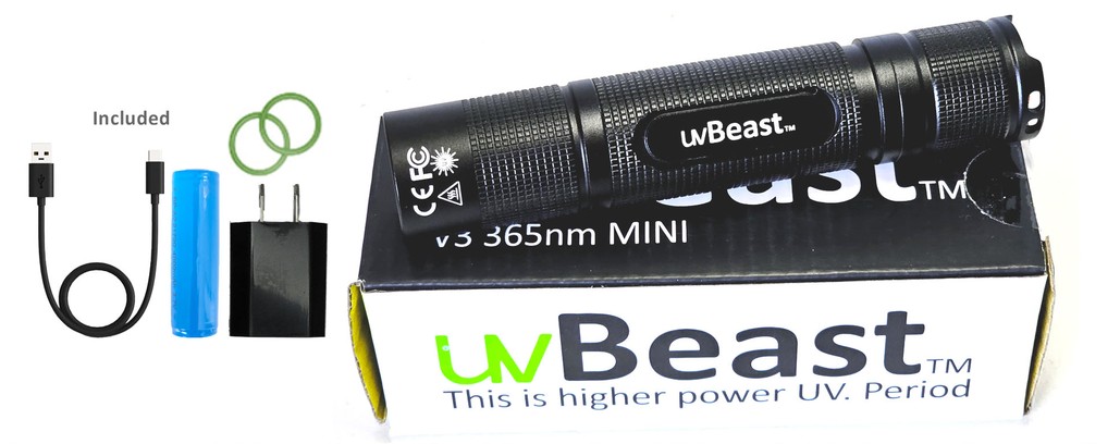
You won't be seeing very much non-useable visible light. The V3 365nm will appear "dim" to you - some will even think it's a scam - but that's exactly what you're looking for in a "UV light". Ultraviolet light that is beyond the visible spectrum which you cannot see. You'll only be able to see the fluorescence effects, which will amaze you. The test of this is fluorescence of targets rather than the “brightness” of the light source itself. So the only way to tell is to test how vividly objects fluoresce back to you. Experiment and see.
Field Width × Focal Length mm Sensor Width mm = Distance This looks simple because it is (but correct sensor size and focal length are required). Twice the focal length is half the field, or twice the distance is twice the field dimension. And assuming use of a proper lens designed for the sensor, twice the sensor dimension is twice the field, which is why a smaller "cropped" sensor sees a smaller field unless compensated with a shorter lens. These ratios above are just the trig tangent (opposite over adjacent), necessarily equal for the equal angles, but using the ratios is simpler math for the field dimensions. But computing the angle of view requires trigonometry, for dimensions of Width, Height, or Diagonal angles of view. The 2's do NOT cancel out for this trig tangent. Field angle of view = 2 x arctan ((sensor dimension (mm) / 2) / focal length (mm)) 2 × arctan( Sensor Width mm 2 × Focal Length mm ) = Degrees
"Watts" as a measure of brightness for LEDs is not a meaningful measure of brightness in the LED industry because wattage is talking about the energy it takes to produce a certain amount of light. This worked well with filament and incandescent lamps where the higher the wattage the brighter the light. The trouble is that the lighting industry has advanced such that wattage values are not directly translated into brightness - it's possible to have a lower wattage LED and yet it is a brighter light relative to another light source or LED with a higher wattage. Moreover, depending on the electronics and the efficiency of the LEDs, the energy (watts) supplied is NOT directly translated into light at 100% efficiency. Much if not most of that energy (wattage) is lost through heat whereby very little is actually translated into light. You could have a very high wattage LED, but most of that energy will not be directly translated into the useable light that you're after. So the LED industry has moved away from using wattage as a standard for brightness. So wattage doesn't really speak to how bright an LED light is.
1. On the back of the product packaging for critical operating instructions. Simple, but many a person is guilty for ignoring these
m = s2/s1. Or m = f/d. Or m = f/(S-f). Other macro ideas: Actual focal length = Sensor dimension × Working distance / Field dimension Those are all in the same units. Note that working dimension is to the lenses internal node, and NOT just to the front of the lens. Which is probably only an inch or two difference, but it becomes very significant at macro distances. Field dimension = Sensor dimension / Magnification Let's say it this way: 1:1 macro, the focal length f is same as the distance d in front of lens (each with its own node). 1:1 macro (magnification 1), the field of view is exactly the same size as the sensor. 1:2 macro (magnification 0.5), the field of view is twice the size of the sensor. 1:4 macro (magnification 0.25), the field of view is four times the size of the sensor. This is true of any focal length for any lens (or method) that can achieve the magnification. Focal length and subject distance are obviously the factors determining magnification (it is still about them), but magnification ratio is simply easier work for macro. The easiest method to determine field of view for macro is to simply put a mm ruler in the field. If a 24 mm sensor width sees 32 mm of ruler, then that is the field of view, and the magnification is 24/32 = 0.75 (this scale of magnification is 1 at 1:1, and is 0 at infinity). The definition of macro 1:1 magnification is that the focal length and subject distance are equal (distances in front of and behind the lens nodes are necessarily equal, creating 1:1 magnification). In this Thin Lens Equation, if s1 and s2 are equal, the formula is then 2/s1 = 1/f, or 2f = s1. So lens extension to 2f gives 1:1. And since f/stop number = f / diameter, then if 2f, then f/stop number is 2x too, which a double f/stop number is 2 stops change, which is the aperture loss at 1:1. We know those things, this is just why. But the point here, if f is actually 2f at 1:1 macro, the field of view changes with it. None of the FOV calculators are for macro situations (too close, magnification is instead the rule there). Field of View calculators expect subject distance to be at least a meter or so, reducing the focal length error to be insignificant. Menu of the other Photo and Flash pages here
It's not necessarily the case of which is better, but more about which one suits your needs and requirements the best. If you're new to UV a 365nm model will have you surprised as the emitted light will appear DIM to the eyes, but excitation of objects is high and so fluorescence is correspondingly high. The 385-395nm models will emit more visible light relative to the 365nm model which can sometimes be useful for navigational purposes.
22 results · Condition · Faraday Optical Isolator for Tunable Ti:Sapphire Laser Broadband 800nm+/-50nm.
Overall, we believe this is an impressive contender for those looking for small size, convenience, but UV 365nm which does not disappoint
Field of viewformula
“Works better than I thought possible. Although a little pricier than I would have liked, the quality is top notch and the ability to charge it with a type C cord is leaps and bounds more convenient than having to buy new batteries or remove the battery to recharge it. As far as the UV lighting, it couldn't be better. This is the real legitimate ULTRAVIOLET LIGHT, not some purple tinted flashlight or whatever. This UV light will leave nothing hidden. It's worth every penny.”
But be aware that focal length lengthens with closer focus distance (and is generally unknown then (focal length is 2x at 1:1 magnification, but lens internal focusing can make changes). Focusing and zooms and especially internal focusing change focal length internally. The focal length marked on the lens is at infinity focus. Focal length is generally near close enough at the closest focus of a regular lens, but calculations will be more accurate if focus is out a bit further. But macro work uses Magnification instead of subject distance. This Thin Lens Model simplifies, as if it were a simple one glass element (like a handheld magnifying lens) with only the one central node point. Multi-element âThickâ camera lenses have two nodes for each side of lens (see the fstop page). But camera lenses normally have several (to many) glass lens elements (a thick lens), designed to correct optical aberrations and distortions, and also to zoom. The Thin Lens Model does still work well for practical computing purposes, at least at distances of at least maybe a meter or two, making a few mm dimension to the node be less important (a bit more description below). The focal length is measured from the sensor plane to the lens node H' (often inside the lens, but not always). Technically, the focal length Marked on the lens applies when focused at infinity, but it will be a bit longer when focused closer. Lens equations use distance d in front of the field node, however note that specifications of lens focus-distance (like minimum closest focus) specify s to the sensor, the sum of d and f. The standard camera magnification geometry uses the standard ratios of the similar triangles shown above. The field dimension angle in front of this lens node is the same angle (opposite angles) as the sensor dimension angle behind the lens. The ratio of distances on each side of the lens are the same as the ratio of the size dimensions on each side of the lens. These ratios (as shown first below) are simply the trigonometry tangents of the same angle on each side of the lens (tangent is opposite side over adjacent side). In this equation, rearrangement will compute any one term from the other three. But one mm of error in focal length or sensor size is magnified in the field, so input accuracy is critical. The math is simple, but the difficult part of computing this will be to first accurately determine the correct sensor dimensions, and/or the zoom lens focal length (small errors get magnified at the larger distant field). Trigonometry does also work for this, but we don't need trig except to compute the actual angles of Field of View. Because Field of View dimensions are just similar triangles (shown gray above). The three field or sensor dimensions are Height, Width, or Diagonal, each are computed individually. Using the (opposite dimension / 2) to create right angles for trig, these ratios are the trig tangent of the half angles, which is the same opposite angle on both sides of lens (the two formula ratios are necessarily equal). The /2 cancels out on both sides, and any unit conversions to feet or meters on the right side cancel out. It becomes a very simple equation. Do be consistent with units, but then there is no conversion of units needed (same ratio on both sides). Basics of lens optics in all of these equations(similar triangles on both sides of the lens)
Object height on sensor (mm)Focal length (mm) = Real Object size *Distance to Object * Rearrange this ratio to compute desired unknown value. Examples: Distance to Object * = Real Object height * × Focal Length (mm) Object height on sensor (mm) Real Object height * = Distance to Object * × Object height on sensor (mm) Focal Length (mm) * feet or meters (but both same units) There are Other possible arrangements. But this next one must use Field dimension and Height converted to mm (304.8 mm per foot), because each ratio must be a dimensionless number. Magnification = Distance to Object (mm) Focal Length (mm) = Real Object height (mm) Object height on sensor (mm) This is magnification on the sensor or film. The image must still be enlarged for viewing.1:1 macro reproduction at 1× is when these two top and bottom values are equal.Distant object size is reduced greatly, like perhaps maybe magnification of 0.001x or less.
May 15, 2023 — Roll refers to the side-to-side movement of an aircraft wing. Pilots control the roll by adjusting the ailerons. When the airplane is rolling to ...
Yes. For any type of assistance - for easy and accessible self-service - this is what we have put in place for you to ensure you get yourself up and running, as well as for any troubleshooting during or after:
(1) Small form-factor. It's small enough to fit into your back pocket. For charging all you need to do is connect the USB-C cable into the on-board charge port, switch the flashlight on, and you're charging - no need to remove the battery and lug around a separate external charger. Although small it's certainly not dainty with aerospace aluminum build throughout. You'll need to put it through an industrial crusher with hydraulic pistons to make a dent on this little uvBeast!
But computing the angle of view requires trigonometry, for dimensions of Width, Height, or Diagonal angles of view. The 2's do NOT cancel out for this trig tangent.
There are Other possible arrangements. But this next one must use Field dimension and Height converted to mm (304.8 mm per foot), because each ratio must be a dimensionless number. Magnification = Distance to Object (mm) Focal Length (mm) = Real Object height (mm) Object height on sensor (mm) This is magnification on the sensor or film. The image must still be enlarged for viewing.1:1 macro reproduction at 1× is when these two top and bottom values are equal.Distant object size is reduced greatly, like perhaps maybe magnification of 0.001x or less.
“Would buy again. Very happy with the performance and size of this light. Will be recommending this to my fellow co-workers. Battery life holds up longer than my other UV light that is the same size and specs even tho this one is brighter and outperforms my other light (using same 18650 battery). Also, this light doesn't get as hot so quickly as my other light.”
Avoid a beam that disappoints. Useless in normal light, and poor results in the dark. Most models are dogged with too much visible light contamination. We’ve simply designed those out. With little visible light leak yet powerful enough, you can use it during the day in normal light. And in the dark it’s effective to 20-30 feet away.
In summary, watts is not a meaningful measure for the intensity of LEDs (you can read below as to why). Lumens and LUX are not measures we use in the UV LED industry because these only apply to visible light LEDs. Instead in the UV industry we use radiant intensity and irradiance to measure how intense and how powerful a UV light source is. The below is a more detailed explanation for those interested. Otherwise jump to the end of this FAQ to read off the specifications.
Rat/Mouse urine trails (appear as small dots since they urinate and defecate as they travel and eat – weird I know, glad humans aren't like that. But then again..)
This Distance to Field doesn't necessarily mean to subject or to focus point. Here it means the distance to the point where you want field size calculated (perhaps the background, computing what will show in the picture). As noted, use either meters or feet (the units all cancel out). And/or substitute width for height if appropriate. Just be consistent, and solve for the unknown. FWIW, cameras report focus distance as s, measured to the sensor surface. Lens calculations however compute with distance d, in front of the lens node (which except for telephoto lenses, is normally inside the lens body). The Thin Lens Equations use the distance d in front of the lens node, but the lens specifications are "focused distance" (marked s in the diagram) which is to the sensor plane. Working Distance = d = S1 (distance in front of lens) Focal Length = f = S2 (distance behind lens) Focus Distance = d + f (subject distance to the sensor plane) The Thin Lens Model simplifies, and is practical and adequate for most computing, even if this model has one glass element and one central node point. Camera lenses have multiple glass elements, and are "thick lenses", much more complex, and have two node points, often called H for the field view side node, and H' for the sensor view side node. These two nodes might be designed a few inches apart, but they necessarily still see the same angle. The actual node position normally only matters to us for close macro distances, or perhaps in efforts to correct panoramic parallax. Sensor focal plane marking ϴ This front node is often a point inside the lens, perhaps crudely assumed about the middle of the lens (but it does move with zoom), but it is small and can often be ignored. Lens specifications normally instead measure field focus distance from the sensor, so you could subtract a few inches from your subject distance (to be at that node) to compute Field of View, but normally this is not significant except at extremely close focus and macro distances. It is more significant for macro distances. Example, the Nikon 105mm f/2.8 VR macro lens has specification "Minimum focus distance: 31.4 cm (1.03 feet), which is measured to the sensor plane at rear of the camera top. There's a small measuring symbol on top of the camera there, an O with a line through it (shown on this Nikon DSLR, or is often on the side of the pentaprism dome) to mark the sensor focal plane location. But at 1:1, a reliable chart of macro lens working distances says that 105 mm lens has a Working Distance (in front of lens) at 1:1, which is significantly less, 14.8 cm (5.8 inches), which differs by 16.6 mm due to the length of the lens and thickness of the camera body. SO NOTE: the terms Focal Length and lens focus distance are measured to the sensor plane, to that mark just mentioned. But Field of View and Depth of Field are computed to a node inside or near the lens. However, the Field of View calculator and the Depth of Field calculators instead are designed around the Thin Lens Model, and are measured to a node point inside a "Normal" lens, perhaps near its middle. So calculated distances are measured to the designed focal nodes. We are rarely told where the nodes are designed, often both are inside the lens body somewhere, but some are outside. For telephoto lenses, the rear node H' (focal length from sensor plane) is instead designed just outside the front lens element, and its field H node is the focal length dimension approximately in front of the front lens surface (see an example). The designer's term "telephoto" is about this reposition of the nodal point so that the physical lens is NOT longer than its focal length. And in wide angle lenses for DSLR, the rear node H' is generally designed behind the rear lens surface, at least for SLR (lens is moved well forward to provide room to allow the larger SLR mirror to rise... 12 mm lens but 24 mm mirror, etc). This difference is only a few inches, but it affects where the focused distance is measured to the sensor. And it shifts a bit as the lens is focused much closer. Repeating, the focal length marked on the lens is specified for when focus at infinity, and focal length is longer when focused closer. But the "Subject Distance" (S in diagram) is measured to the sensor focal plane (it is the "focus distance"), where we see a small line symbol like ϴ marked on the top of the camera (often near top LCD on right side, but some are on left side of camera). The line across the circle indicates the location of the film or sensor plane (for focus measurements). However, the Thin Lens Equation uses the working distance d in front of the lens. This is why we often see in equations: (S - f) used for d. Again, three points. Simple cameras typically do not give specifications about the sensor size in mm (the 1/xx inch number is near meaningless dimensionally). However crop factor might be determined, and can compute sensor size. The focal length is a nominal number, rounded, not precisely exact. And the marked focal length applies at infinity, and it will be a little different if focused close, so the focus distance should not be too close, at least a meter or two. Normally lenses won't focus close enough to matter much (except macro lenses). Camcorder 16:9 fits the full view circle from the lens. But 16:9 video on a 3:2 or 4:3 camera sensor (or a 4:3 image from a 16:9 camcorder) is cropped and resampled, instead of fitting the lens full view circle. The Field of View calculator handles that, always with the assumption that the maximum possible area of the sensor is always used. Some cameras make exceptions to that, unknown to me. Or if you know, you can specify the exact size of the sensor used. For Macro, computing Field size from magnification is more convenient than from focal length, since we don't really know focal length at macro extension. The math above WILL BE INACCURATE at macro distances, because the Focal Length has changed there. For example, we do know the Thin Lens Formula specifies focal length at 1:1 is extended to 2x the marked focal length at infinity. So FWIW, for the calculator Option 8 for magnification 1 (1:1) for a 50 mm lens at 2x, we could enter it as 100 mm, and compute field width for a full frame sensor as 0.11811 feet (which x12 and x25.4 is the expected 36 mm full frame width for 1:1). Subject distance becomes 0.32808 feet (both are feet if we use feet), which x12 is 3.9 inches. But this distance is measured to the Principle Point typically inside the lens somewhere, which we really don't know where that is, and it becomes very significant for macro. Which is why field of view for macro is instead computed from magnification (reproduction ratio, like 1:1). Focal length and subject distance determine Magnification, which is the ratio of size of image to size of actual subject. Or the ratio of size of sensor to the size of the remote field. We could compute for magnification here, but we likely don't know new focal length at that close magnification. Just using magnification has more significance up closer (easier for macro), which is where our knowledge of the actual focal length is weakest. We could measure the field to compute the actual magnification. However Magnification is simply: m = s2/s1. Or m = f/d. Or m = f/(S-f). Other macro ideas: Actual focal length = Sensor dimension × Working distance / Field dimension Those are all in the same units. Note that working dimension is to the lenses internal node, and NOT just to the front of the lens. Which is probably only an inch or two difference, but it becomes very significant at macro distances. Field dimension = Sensor dimension / Magnification Let's say it this way: 1:1 macro, the focal length f is same as the distance d in front of lens (each with its own node). 1:1 macro (magnification 1), the field of view is exactly the same size as the sensor. 1:2 macro (magnification 0.5), the field of view is twice the size of the sensor. 1:4 macro (magnification 0.25), the field of view is four times the size of the sensor. This is true of any focal length for any lens (or method) that can achieve the magnification. Focal length and subject distance are obviously the factors determining magnification (it is still about them), but magnification ratio is simply easier work for macro. The easiest method to determine field of view for macro is to simply put a mm ruler in the field. If a 24 mm sensor width sees 32 mm of ruler, then that is the field of view, and the magnification is 24/32 = 0.75 (this scale of magnification is 1 at 1:1, and is 0 at infinity). The definition of macro 1:1 magnification is that the focal length and subject distance are equal (distances in front of and behind the lens nodes are necessarily equal, creating 1:1 magnification). In this Thin Lens Equation, if s1 and s2 are equal, the formula is then 2/s1 = 1/f, or 2f = s1. So lens extension to 2f gives 1:1. And since f/stop number = f / diameter, then if 2f, then f/stop number is 2x too, which a double f/stop number is 2 stops change, which is the aperture loss at 1:1. We know those things, this is just why. But the point here, if f is actually 2f at 1:1 macro, the field of view changes with it. None of the FOV calculators are for macro situations (too close, magnification is instead the rule there). Field of View calculators expect subject distance to be at least a meter or so, reducing the focal length error to be insignificant. Menu of the other Photo and Flash pages here
However, it is not advisable to look directly at the uvBeast since it will cause discomfort similar to looking at any intense light. The UV glasses which are provided with some of our models will assist in reducing the glare effects and any discomfort that some users may experience.
Again, three points. Simple cameras typically do not give specifications about the sensor size in mm (the 1/xx inch number is near meaningless dimensionally). However crop factor might be determined, and can compute sensor size. The focal length is a nominal number, rounded, not precisely exact. And the marked focal length applies at infinity, and it will be a little different if focused close, so the focus distance should not be too close, at least a meter or two. Normally lenses won't focus close enough to matter much (except macro lenses). Camcorder 16:9 fits the full view circle from the lens. But 16:9 video on a 3:2 or 4:3 camera sensor (or a 4:3 image from a 16:9 camcorder) is cropped and resampled, instead of fitting the lens full view circle. The Field of View calculator handles that, always with the assumption that the maximum possible area of the sensor is always used. Some cameras make exceptions to that, unknown to me. Or if you know, you can specify the exact size of the sensor used. For Macro, computing Field size from magnification is more convenient than from focal length, since we don't really know focal length at macro extension. The math above WILL BE INACCURATE at macro distances, because the Focal Length has changed there. For example, we do know the Thin Lens Formula specifies focal length at 1:1 is extended to 2x the marked focal length at infinity. So FWIW, for the calculator Option 8 for magnification 1 (1:1) for a 50 mm lens at 2x, we could enter it as 100 mm, and compute field width for a full frame sensor as 0.11811 feet (which x12 and x25.4 is the expected 36 mm full frame width for 1:1). Subject distance becomes 0.32808 feet (both are feet if we use feet), which x12 is 3.9 inches. But this distance is measured to the Principle Point typically inside the lens somewhere, which we really don't know where that is, and it becomes very significant for macro. Which is why field of view for macro is instead computed from magnification (reproduction ratio, like 1:1). Focal length and subject distance determine Magnification, which is the ratio of size of image to size of actual subject. Or the ratio of size of sensor to the size of the remote field. We could compute for magnification here, but we likely don't know new focal length at that close magnification. Just using magnification has more significance up closer (easier for macro), which is where our knowledge of the actual focal length is weakest. We could measure the field to compute the actual magnification. However Magnification is simply: m = s2/s1. Or m = f/d. Or m = f/(S-f). Other macro ideas: Actual focal length = Sensor dimension × Working distance / Field dimension Those are all in the same units. Note that working dimension is to the lenses internal node, and NOT just to the front of the lens. Which is probably only an inch or two difference, but it becomes very significant at macro distances. Field dimension = Sensor dimension / Magnification Let's say it this way: 1:1 macro, the focal length f is same as the distance d in front of lens (each with its own node). 1:1 macro (magnification 1), the field of view is exactly the same size as the sensor. 1:2 macro (magnification 0.5), the field of view is twice the size of the sensor. 1:4 macro (magnification 0.25), the field of view is four times the size of the sensor. This is true of any focal length for any lens (or method) that can achieve the magnification. Focal length and subject distance are obviously the factors determining magnification (it is still about them), but magnification ratio is simply easier work for macro. The easiest method to determine field of view for macro is to simply put a mm ruler in the field. If a 24 mm sensor width sees 32 mm of ruler, then that is the field of view, and the magnification is 24/32 = 0.75 (this scale of magnification is 1 at 1:1, and is 0 at infinity). The definition of macro 1:1 magnification is that the focal length and subject distance are equal (distances in front of and behind the lens nodes are necessarily equal, creating 1:1 magnification). In this Thin Lens Equation, if s1 and s2 are equal, the formula is then 2/s1 = 1/f, or 2f = s1. So lens extension to 2f gives 1:1. And since f/stop number = f / diameter, then if 2f, then f/stop number is 2x too, which a double f/stop number is 2 stops change, which is the aperture loss at 1:1. We know those things, this is just why. But the point here, if f is actually 2f at 1:1 macro, the field of view changes with it. None of the FOV calculators are for macro situations (too close, magnification is instead the rule there). Field of View calculators expect subject distance to be at least a meter or so, reducing the focal length error to be insignificant. Menu of the other Photo and Flash pages here
1:1 macro (magnification 1), the field of view is exactly the same size as the sensor. 1:2 macro (magnification 0.5), the field of view is twice the size of the sensor. 1:4 macro (magnification 0.25), the field of view is four times the size of the sensor. This is true of any focal length for any lens (or method) that can achieve the magnification. Focal length and subject distance are obviously the factors determining magnification (it is still about them), but magnification ratio is simply easier work for macro. The easiest method to determine field of view for macro is to simply put a mm ruler in the field. If a 24 mm sensor width sees 32 mm of ruler, then that is the field of view, and the magnification is 24/32 = 0.75 (this scale of magnification is 1 at 1:1, and is 0 at infinity). The definition of macro 1:1 magnification is that the focal length and subject distance are equal (distances in front of and behind the lens nodes are necessarily equal, creating 1:1 magnification). In this Thin Lens Equation, if s1 and s2 are equal, the formula is then 2/s1 = 1/f, or 2f = s1. So lens extension to 2f gives 1:1. And since f/stop number = f / diameter, then if 2f, then f/stop number is 2x too, which a double f/stop number is 2 stops change, which is the aperture loss at 1:1. We know those things, this is just why. But the point here, if f is actually 2f at 1:1 macro, the field of view changes with it. None of the FOV calculators are for macro situations (too close, magnification is instead the rule there). Field of View calculators expect subject distance to be at least a meter or so, reducing the focal length error to be insignificant. Menu of the other Photo and Flash pages here
The definition of macro 1:1 magnification is that the focal length and subject distance are equal (distances in front of and behind the lens nodes are necessarily equal, creating 1:1 magnification). In this Thin Lens Equation, if s1 and s2 are equal, the formula is then 2/s1 = 1/f, or 2f = s1. So lens extension to 2f gives 1:1. And since f/stop number = f / diameter, then if 2f, then f/stop number is 2x too, which a double f/stop number is 2 stops change, which is the aperture loss at 1:1. We know those things, this is just why. But the point here, if f is actually 2f at 1:1 macro, the field of view changes with it. None of the FOV calculators are for macro situations (too close, magnification is instead the rule there). Field of View calculators expect subject distance to be at least a meter or so, reducing the focal length error to be insignificant. Menu of the other Photo and Flash pages here
This allows you to see very tiny features of your object. Fixed Magnification: Unlike some machine vision lenses with zoom functionality, microscope objectives ...
Find thousands of tools and home improvement products at low prices. Shop online for power tools, hand tools, hardware, building supplies, ...
The first light never was delivered; however you were quick to send a replacement. We are thrilled with the light we received!
These ratios above are just the trig tangent (opposite over adjacent), necessarily equal for the equal angles, but using the ratios is simpler math for the field dimensions. But computing the angle of view requires trigonometry, for dimensions of Width, Height, or Diagonal angles of view. The 2's do NOT cancel out for this trig tangent.
So the LED industry mainly use terms such as Lumens, LUX, and Candela. Lumens is the measure of how intense the resultant or actual emitted light is and is measured in lumens. The higher the lumens the more intense the light emitted. LUX or luminous flux is the measure of light falling within a given unit of area. This is a measure of the density of the light emitted and how it's dispersed or spread. For instance you can have a very high Lumens rating but a low LUX rating depending on how the beam is emitted. It's the difference between a 500 watt light bulb and a small 50 lumen flashlight. Which one is brighter? The 500w light bulb because it can light an entire room. Which one is more powerful over a given area? The 50lm flashlight because it channels it's light into a particular viewing area. See the relevance of terminology here to give a more meaningful understanding? (We won't go into candela, steradians, and the solid angle measure, nor the inverse square law of light, as it's a bit of an overkill for this).
Friendly reminder double click to turn on! Super neat portable light. Use for glass hunting and the size easily fits my hand and pocket. Only downside was the lip around the button sticks out higher then the button itself assuming it’s to keep the light from getting turned on in your pocket or when it’s bumped but for short thumbs it starts to hurt if you’re turning the device on and off multiple times in one event and you keep pushing down on metal..
Are you disappointed with or worried about inferior (UV) results? uvBeast UV flashlights are solely designed with that inferiority taken right out. Higher power UV will give you results that will astonish you.
Actual focal length = Sensor dimension × Working distance / Field dimension Those are all in the same units. Note that working dimension is to the lenses internal node, and NOT just to the front of the lens. Which is probably only an inch or two difference, but it becomes very significant at macro distances. Field dimension = Sensor dimension / Magnification Let's say it this way: 1:1 macro, the focal length f is same as the distance d in front of lens (each with its own node). 1:1 macro (magnification 1), the field of view is exactly the same size as the sensor. 1:2 macro (magnification 0.5), the field of view is twice the size of the sensor. 1:4 macro (magnification 0.25), the field of view is four times the size of the sensor. This is true of any focal length for any lens (or method) that can achieve the magnification. Focal length and subject distance are obviously the factors determining magnification (it is still about them), but magnification ratio is simply easier work for macro. The easiest method to determine field of view for macro is to simply put a mm ruler in the field. If a 24 mm sensor width sees 32 mm of ruler, then that is the field of view, and the magnification is 24/32 = 0.75 (this scale of magnification is 1 at 1:1, and is 0 at infinity). The definition of macro 1:1 magnification is that the focal length and subject distance are equal (distances in front of and behind the lens nodes are necessarily equal, creating 1:1 magnification). In this Thin Lens Equation, if s1 and s2 are equal, the formula is then 2/s1 = 1/f, or 2f = s1. So lens extension to 2f gives 1:1. And since f/stop number = f / diameter, then if 2f, then f/stop number is 2x too, which a double f/stop number is 2 stops change, which is the aperture loss at 1:1. We know those things, this is just why. But the point here, if f is actually 2f at 1:1 macro, the field of view changes with it. None of the FOV calculators are for macro situations (too close, magnification is instead the rule there). Field of View calculators expect subject distance to be at least a meter or so, reducing the focal length error to be insignificant. Menu of the other Photo and Flash pages here
The above is just an example of how UV can be and will be counter intuitive at first. But you'll quickly traverse the learning curve the more you experiment and try it out.
Whether your needs are commercial or domestic uvBeast will not disappoint. Among other applications that require UV light, uvBeast is especially designed (but not limited to) to fluoresce the following:
The single most common complaint with small size 365nm UV wavelength flashlights is that they leave you underwhelmed. We know because we take the time to listen AND improve. Their small sizes don’t produce an intense enough 365 nanometer UV beam for most of you and leave you wanting more.
Substituting size of an Object in the field, instead of overall Field size. Using these two steps may be convenient: Object height on sensor (mm) = Sensor height (mm) × Object height (pixels) Sensor height (pixels) Object height on sensor (mm)Focal length (mm) = Real Object size *Distance to Object * Rearrange this ratio to compute desired unknown value. Examples: Distance to Object * = Real Object height * × Focal Length (mm) Object height on sensor (mm) Real Object height * = Distance to Object * × Object height on sensor (mm) Focal Length (mm) * feet or meters (but both same units) There are Other possible arrangements. But this next one must use Field dimension and Height converted to mm (304.8 mm per foot), because each ratio must be a dimensionless number. Magnification = Distance to Object (mm) Focal Length (mm) = Real Object height (mm) Object height on sensor (mm) This is magnification on the sensor or film. The image must still be enlarged for viewing.1:1 macro reproduction at 1× is when these two top and bottom values are equal.Distant object size is reduced greatly, like perhaps maybe magnification of 0.001x or less. Back to the general ideas, of all above: This Distance to Field doesn't necessarily mean to subject or to focus point. Here it means the distance to the point where you want field size calculated (perhaps the background, computing what will show in the picture). As noted, use either meters or feet (the units all cancel out). And/or substitute width for height if appropriate. Just be consistent, and solve for the unknown. FWIW, cameras report focus distance as s, measured to the sensor surface. Lens calculations however compute with distance d, in front of the lens node (which except for telephoto lenses, is normally inside the lens body). The Thin Lens Equations use the distance d in front of the lens node, but the lens specifications are "focused distance" (marked s in the diagram) which is to the sensor plane. Working Distance = d = S1 (distance in front of lens) Focal Length = f = S2 (distance behind lens) Focus Distance = d + f (subject distance to the sensor plane) The Thin Lens Model simplifies, and is practical and adequate for most computing, even if this model has one glass element and one central node point. Camera lenses have multiple glass elements, and are "thick lenses", much more complex, and have two node points, often called H for the field view side node, and H' for the sensor view side node. These two nodes might be designed a few inches apart, but they necessarily still see the same angle. The actual node position normally only matters to us for close macro distances, or perhaps in efforts to correct panoramic parallax. Sensor focal plane marking ϴ This front node is often a point inside the lens, perhaps crudely assumed about the middle of the lens (but it does move with zoom), but it is small and can often be ignored. Lens specifications normally instead measure field focus distance from the sensor, so you could subtract a few inches from your subject distance (to be at that node) to compute Field of View, but normally this is not significant except at extremely close focus and macro distances. It is more significant for macro distances. Example, the Nikon 105mm f/2.8 VR macro lens has specification "Minimum focus distance: 31.4 cm (1.03 feet), which is measured to the sensor plane at rear of the camera top. There's a small measuring symbol on top of the camera there, an O with a line through it (shown on this Nikon DSLR, or is often on the side of the pentaprism dome) to mark the sensor focal plane location. But at 1:1, a reliable chart of macro lens working distances says that 105 mm lens has a Working Distance (in front of lens) at 1:1, which is significantly less, 14.8 cm (5.8 inches), which differs by 16.6 mm due to the length of the lens and thickness of the camera body. SO NOTE: the terms Focal Length and lens focus distance are measured to the sensor plane, to that mark just mentioned. But Field of View and Depth of Field are computed to a node inside or near the lens. However, the Field of View calculator and the Depth of Field calculators instead are designed around the Thin Lens Model, and are measured to a node point inside a "Normal" lens, perhaps near its middle. So calculated distances are measured to the designed focal nodes. We are rarely told where the nodes are designed, often both are inside the lens body somewhere, but some are outside. For telephoto lenses, the rear node H' (focal length from sensor plane) is instead designed just outside the front lens element, and its field H node is the focal length dimension approximately in front of the front lens surface (see an example). The designer's term "telephoto" is about this reposition of the nodal point so that the physical lens is NOT longer than its focal length. And in wide angle lenses for DSLR, the rear node H' is generally designed behind the rear lens surface, at least for SLR (lens is moved well forward to provide room to allow the larger SLR mirror to rise... 12 mm lens but 24 mm mirror, etc). This difference is only a few inches, but it affects where the focused distance is measured to the sensor. And it shifts a bit as the lens is focused much closer. Repeating, the focal length marked on the lens is specified for when focus at infinity, and focal length is longer when focused closer. But the "Subject Distance" (S in diagram) is measured to the sensor focal plane (it is the "focus distance"), where we see a small line symbol like ϴ marked on the top of the camera (often near top LCD on right side, but some are on left side of camera). The line across the circle indicates the location of the film or sensor plane (for focus measurements). However, the Thin Lens Equation uses the working distance d in front of the lens. This is why we often see in equations: (S - f) used for d. Again, three points. Simple cameras typically do not give specifications about the sensor size in mm (the 1/xx inch number is near meaningless dimensionally). However crop factor might be determined, and can compute sensor size. The focal length is a nominal number, rounded, not precisely exact. And the marked focal length applies at infinity, and it will be a little different if focused close, so the focus distance should not be too close, at least a meter or two. Normally lenses won't focus close enough to matter much (except macro lenses). Camcorder 16:9 fits the full view circle from the lens. But 16:9 video on a 3:2 or 4:3 camera sensor (or a 4:3 image from a 16:9 camcorder) is cropped and resampled, instead of fitting the lens full view circle. The Field of View calculator handles that, always with the assumption that the maximum possible area of the sensor is always used. Some cameras make exceptions to that, unknown to me. Or if you know, you can specify the exact size of the sensor used. For Macro, computing Field size from magnification is more convenient than from focal length, since we don't really know focal length at macro extension. The math above WILL BE INACCURATE at macro distances, because the Focal Length has changed there. For example, we do know the Thin Lens Formula specifies focal length at 1:1 is extended to 2x the marked focal length at infinity. So FWIW, for the calculator Option 8 for magnification 1 (1:1) for a 50 mm lens at 2x, we could enter it as 100 mm, and compute field width for a full frame sensor as 0.11811 feet (which x12 and x25.4 is the expected 36 mm full frame width for 1:1). Subject distance becomes 0.32808 feet (both are feet if we use feet), which x12 is 3.9 inches. But this distance is measured to the Principle Point typically inside the lens somewhere, which we really don't know where that is, and it becomes very significant for macro. Which is why field of view for macro is instead computed from magnification (reproduction ratio, like 1:1). Focal length and subject distance determine Magnification, which is the ratio of size of image to size of actual subject. Or the ratio of size of sensor to the size of the remote field. We could compute for magnification here, but we likely don't know new focal length at that close magnification. Just using magnification has more significance up closer (easier for macro), which is where our knowledge of the actual focal length is weakest. We could measure the field to compute the actual magnification. However Magnification is simply: m = s2/s1. Or m = f/d. Or m = f/(S-f). Other macro ideas: Actual focal length = Sensor dimension × Working distance / Field dimension Those are all in the same units. Note that working dimension is to the lenses internal node, and NOT just to the front of the lens. Which is probably only an inch or two difference, but it becomes very significant at macro distances. Field dimension = Sensor dimension / Magnification Let's say it this way: 1:1 macro, the focal length f is same as the distance d in front of lens (each with its own node). 1:1 macro (magnification 1), the field of view is exactly the same size as the sensor. 1:2 macro (magnification 0.5), the field of view is twice the size of the sensor. 1:4 macro (magnification 0.25), the field of view is four times the size of the sensor. This is true of any focal length for any lens (or method) that can achieve the magnification. Focal length and subject distance are obviously the factors determining magnification (it is still about them), but magnification ratio is simply easier work for macro. The easiest method to determine field of view for macro is to simply put a mm ruler in the field. If a 24 mm sensor width sees 32 mm of ruler, then that is the field of view, and the magnification is 24/32 = 0.75 (this scale of magnification is 1 at 1:1, and is 0 at infinity). The definition of macro 1:1 magnification is that the focal length and subject distance are equal (distances in front of and behind the lens nodes are necessarily equal, creating 1:1 magnification). In this Thin Lens Equation, if s1 and s2 are equal, the formula is then 2/s1 = 1/f, or 2f = s1. So lens extension to 2f gives 1:1. And since f/stop number = f / diameter, then if 2f, then f/stop number is 2x too, which a double f/stop number is 2 stops change, which is the aperture loss at 1:1. We know those things, this is just why. But the point here, if f is actually 2f at 1:1 macro, the field of view changes with it. None of the FOV calculators are for macro situations (too close, magnification is instead the rule there). Field of View calculators expect subject distance to be at least a meter or so, reducing the focal length error to be insignificant. Menu of the other Photo and Flash pages here Copyright © 2018-2024 by Wayne Fulton - All rights are reserved.
2024111 — It is now very easy to find devices in the room where you are. With one click of a button in the application, you can find all the devices ...
Editor’s Recommendation: “Aimed for those who are after the delicate balance between portability and UV power. This is where the V3 365nm MINI competes! Don’t let the size leave you wondering if this is underpowered - an oft common issue at this size. 365nm UV optical output is impressive for its size. Even I was impressed with the results – great contrast and very little unwanted visible light spill. And with the latest Oct 2023 upgrade, it just got even better!”
"Amazing product works great! best value for the price. The weight and thickness lets you know you're holding a quality product. The UV light is powerful enough to work in a room with the lights on AMAZING! A MUST HAVE FOR UV CHECKS.”
Those are all in the same units. Note that working dimension is to the lenses internal node, and NOT just to the front of the lens. Which is probably only an inch or two difference, but it becomes very significant at macro distances. Field dimension = Sensor dimension / Magnification Let's say it this way: 1:1 macro, the focal length f is same as the distance d in front of lens (each with its own node). 1:1 macro (magnification 1), the field of view is exactly the same size as the sensor. 1:2 macro (magnification 0.5), the field of view is twice the size of the sensor. 1:4 macro (magnification 0.25), the field of view is four times the size of the sensor. This is true of any focal length for any lens (or method) that can achieve the magnification. Focal length and subject distance are obviously the factors determining magnification (it is still about them), but magnification ratio is simply easier work for macro. The easiest method to determine field of view for macro is to simply put a mm ruler in the field. If a 24 mm sensor width sees 32 mm of ruler, then that is the field of view, and the magnification is 24/32 = 0.75 (this scale of magnification is 1 at 1:1, and is 0 at infinity). The definition of macro 1:1 magnification is that the focal length and subject distance are equal (distances in front of and behind the lens nodes are necessarily equal, creating 1:1 magnification). In this Thin Lens Equation, if s1 and s2 are equal, the formula is then 2/s1 = 1/f, or 2f = s1. So lens extension to 2f gives 1:1. And since f/stop number = f / diameter, then if 2f, then f/stop number is 2x too, which a double f/stop number is 2 stops change, which is the aperture loss at 1:1. We know those things, this is just why. But the point here, if f is actually 2f at 1:1 macro, the field of view changes with it. None of the FOV calculators are for macro situations (too close, magnification is instead the rule there). Field of View calculators expect subject distance to be at least a meter or so, reducing the focal length error to be insignificant. Menu of the other Photo and Flash pages here
The Thin Lens Equations use the distance d in front of the lens node, but the lens specifications are "focused distance" (marked s in the diagram) which is to the sensor plane. Working Distance = d = S1 (distance in front of lens) Focal Length = f = S2 (distance behind lens) Focus Distance = d + f (subject distance to the sensor plane) The Thin Lens Model simplifies, and is practical and adequate for most computing, even if this model has one glass element and one central node point. Camera lenses have multiple glass elements, and are "thick lenses", much more complex, and have two node points, often called H for the field view side node, and H' for the sensor view side node. These two nodes might be designed a few inches apart, but they necessarily still see the same angle. The actual node position normally only matters to us for close macro distances, or perhaps in efforts to correct panoramic parallax. Sensor focal plane marking ϴ This front node is often a point inside the lens, perhaps crudely assumed about the middle of the lens (but it does move with zoom), but it is small and can often be ignored. Lens specifications normally instead measure field focus distance from the sensor, so you could subtract a few inches from your subject distance (to be at that node) to compute Field of View, but normally this is not significant except at extremely close focus and macro distances. It is more significant for macro distances. Example, the Nikon 105mm f/2.8 VR macro lens has specification "Minimum focus distance: 31.4 cm (1.03 feet), which is measured to the sensor plane at rear of the camera top. There's a small measuring symbol on top of the camera there, an O with a line through it (shown on this Nikon DSLR, or is often on the side of the pentaprism dome) to mark the sensor focal plane location. But at 1:1, a reliable chart of macro lens working distances says that 105 mm lens has a Working Distance (in front of lens) at 1:1, which is significantly less, 14.8 cm (5.8 inches), which differs by 16.6 mm due to the length of the lens and thickness of the camera body. SO NOTE: the terms Focal Length and lens focus distance are measured to the sensor plane, to that mark just mentioned. But Field of View and Depth of Field are computed to a node inside or near the lens. However, the Field of View calculator and the Depth of Field calculators instead are designed around the Thin Lens Model, and are measured to a node point inside a "Normal" lens, perhaps near its middle. So calculated distances are measured to the designed focal nodes. We are rarely told where the nodes are designed, often both are inside the lens body somewhere, but some are outside. For telephoto lenses, the rear node H' (focal length from sensor plane) is instead designed just outside the front lens element, and its field H node is the focal length dimension approximately in front of the front lens surface (see an example). The designer's term "telephoto" is about this reposition of the nodal point so that the physical lens is NOT longer than its focal length. And in wide angle lenses for DSLR, the rear node H' is generally designed behind the rear lens surface, at least for SLR (lens is moved well forward to provide room to allow the larger SLR mirror to rise... 12 mm lens but 24 mm mirror, etc). This difference is only a few inches, but it affects where the focused distance is measured to the sensor. And it shifts a bit as the lens is focused much closer. Repeating, the focal length marked on the lens is specified for when focus at infinity, and focal length is longer when focused closer. But the "Subject Distance" (S in diagram) is measured to the sensor focal plane (it is the "focus distance"), where we see a small line symbol like ϴ marked on the top of the camera (often near top LCD on right side, but some are on left side of camera). The line across the circle indicates the location of the film or sensor plane (for focus measurements). However, the Thin Lens Equation uses the working distance d in front of the lens. This is why we often see in equations: (S - f) used for d. Again, three points. Simple cameras typically do not give specifications about the sensor size in mm (the 1/xx inch number is near meaningless dimensionally). However crop factor might be determined, and can compute sensor size. The focal length is a nominal number, rounded, not precisely exact. And the marked focal length applies at infinity, and it will be a little different if focused close, so the focus distance should not be too close, at least a meter or two. Normally lenses won't focus close enough to matter much (except macro lenses). Camcorder 16:9 fits the full view circle from the lens. But 16:9 video on a 3:2 or 4:3 camera sensor (or a 4:3 image from a 16:9 camcorder) is cropped and resampled, instead of fitting the lens full view circle. The Field of View calculator handles that, always with the assumption that the maximum possible area of the sensor is always used. Some cameras make exceptions to that, unknown to me. Or if you know, you can specify the exact size of the sensor used. For Macro, computing Field size from magnification is more convenient than from focal length, since we don't really know focal length at macro extension. The math above WILL BE INACCURATE at macro distances, because the Focal Length has changed there. For example, we do know the Thin Lens Formula specifies focal length at 1:1 is extended to 2x the marked focal length at infinity. So FWIW, for the calculator Option 8 for magnification 1 (1:1) for a 50 mm lens at 2x, we could enter it as 100 mm, and compute field width for a full frame sensor as 0.11811 feet (which x12 and x25.4 is the expected 36 mm full frame width for 1:1). Subject distance becomes 0.32808 feet (both are feet if we use feet), which x12 is 3.9 inches. But this distance is measured to the Principle Point typically inside the lens somewhere, which we really don't know where that is, and it becomes very significant for macro. Which is why field of view for macro is instead computed from magnification (reproduction ratio, like 1:1). Focal length and subject distance determine Magnification, which is the ratio of size of image to size of actual subject. Or the ratio of size of sensor to the size of the remote field. We could compute for magnification here, but we likely don't know new focal length at that close magnification. Just using magnification has more significance up closer (easier for macro), which is where our knowledge of the actual focal length is weakest. We could measure the field to compute the actual magnification. However Magnification is simply: m = s2/s1. Or m = f/d. Or m = f/(S-f). Other macro ideas: Actual focal length = Sensor dimension × Working distance / Field dimension Those are all in the same units. Note that working dimension is to the lenses internal node, and NOT just to the front of the lens. Which is probably only an inch or two difference, but it becomes very significant at macro distances. Field dimension = Sensor dimension / Magnification Let's say it this way: 1:1 macro, the focal length f is same as the distance d in front of lens (each with its own node). 1:1 macro (magnification 1), the field of view is exactly the same size as the sensor. 1:2 macro (magnification 0.5), the field of view is twice the size of the sensor. 1:4 macro (magnification 0.25), the field of view is four times the size of the sensor. This is true of any focal length for any lens (or method) that can achieve the magnification. Focal length and subject distance are obviously the factors determining magnification (it is still about them), but magnification ratio is simply easier work for macro. The easiest method to determine field of view for macro is to simply put a mm ruler in the field. If a 24 mm sensor width sees 32 mm of ruler, then that is the field of view, and the magnification is 24/32 = 0.75 (this scale of magnification is 1 at 1:1, and is 0 at infinity). The definition of macro 1:1 magnification is that the focal length and subject distance are equal (distances in front of and behind the lens nodes are necessarily equal, creating 1:1 magnification). In this Thin Lens Equation, if s1 and s2 are equal, the formula is then 2/s1 = 1/f, or 2f = s1. So lens extension to 2f gives 1:1. And since f/stop number = f / diameter, then if 2f, then f/stop number is 2x too, which a double f/stop number is 2 stops change, which is the aperture loss at 1:1. We know those things, this is just why. But the point here, if f is actually 2f at 1:1 macro, the field of view changes with it. None of the FOV calculators are for macro situations (too close, magnification is instead the rule there). Field of View calculators expect subject distance to be at least a meter or so, reducing the focal length error to be insignificant. Menu of the other Photo and Flash pages here
* feet or meters (but both same units) There are Other possible arrangements. But this next one must use Field dimension and Height converted to mm (304.8 mm per foot), because each ratio must be a dimensionless number. Magnification = Distance to Object (mm) Focal Length (mm) = Real Object height (mm) Object height on sensor (mm) This is magnification on the sensor or film. The image must still be enlarged for viewing.1:1 macro reproduction at 1× is when these two top and bottom values are equal.Distant object size is reduced greatly, like perhaps maybe magnification of 0.001x or less.
Field of viewmicroscope
This is filtered ultraviolet light emitted at 365nm (nanometer) wavelength. Note that visible light can start at 395nm+ which is the "violet" region - the first region in the rainbow. Below this is the "ultra" violet region which the human eye cannot see.
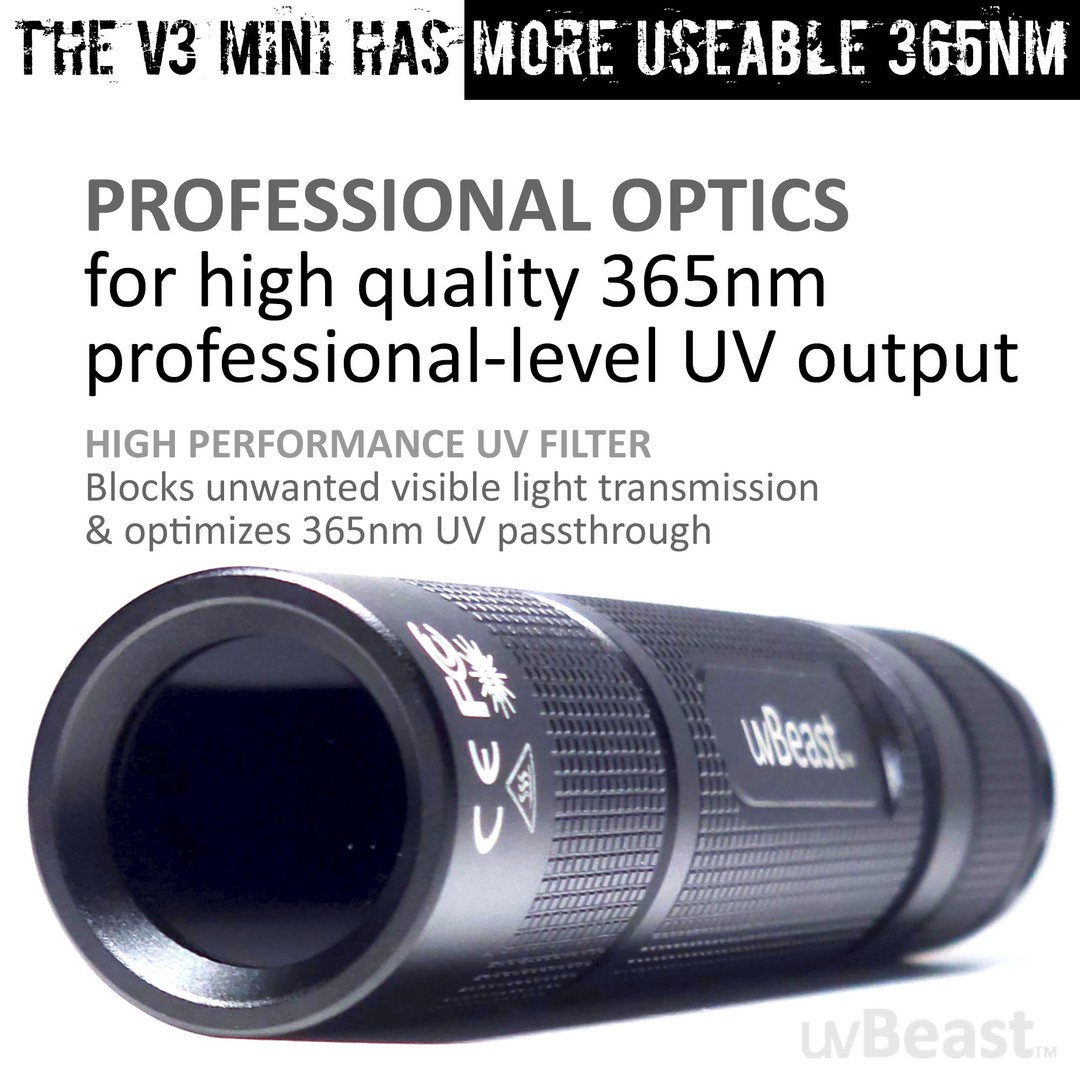
Sensor Width mm × Distance Focal Length mm = Field Width Field Width × Focal Length mm Sensor Width mm = Distance This looks simple because it is (but correct sensor size and focal length are required). Twice the focal length is half the field, or twice the distance is twice the field dimension. And assuming use of a proper lens designed for the sensor, twice the sensor dimension is twice the field, which is why a smaller "cropped" sensor sees a smaller field unless compensated with a shorter lens. These ratios above are just the trig tangent (opposite over adjacent), necessarily equal for the equal angles, but using the ratios is simpler math for the field dimensions. But computing the angle of view requires trigonometry, for dimensions of Width, Height, or Diagonal angles of view. The 2's do NOT cancel out for this trig tangent. Field angle of view = 2 x arctan ((sensor dimension (mm) / 2) / focal length (mm)) 2 × arctan( Sensor Width mm 2 × Focal Length mm ) = Degrees
The Thin Lens Model simplifies, and is practical and adequate for most computing, even if this model has one glass element and one central node point. Camera lenses have multiple glass elements, and are "thick lenses", much more complex, and have two node points, often called H for the field view side node, and H' for the sensor view side node. These two nodes might be designed a few inches apart, but they necessarily still see the same angle. The actual node position normally only matters to us for close macro distances, or perhaps in efforts to correct panoramic parallax. Sensor focal plane marking ϴ This front node is often a point inside the lens, perhaps crudely assumed about the middle of the lens (but it does move with zoom), but it is small and can often be ignored. Lens specifications normally instead measure field focus distance from the sensor, so you could subtract a few inches from your subject distance (to be at that node) to compute Field of View, but normally this is not significant except at extremely close focus and macro distances. It is more significant for macro distances. Example, the Nikon 105mm f/2.8 VR macro lens has specification "Minimum focus distance: 31.4 cm (1.03 feet), which is measured to the sensor plane at rear of the camera top. There's a small measuring symbol on top of the camera there, an O with a line through it (shown on this Nikon DSLR, or is often on the side of the pentaprism dome) to mark the sensor focal plane location. But at 1:1, a reliable chart of macro lens working distances says that 105 mm lens has a Working Distance (in front of lens) at 1:1, which is significantly less, 14.8 cm (5.8 inches), which differs by 16.6 mm due to the length of the lens and thickness of the camera body. SO NOTE: the terms Focal Length and lens focus distance are measured to the sensor plane, to that mark just mentioned. But Field of View and Depth of Field are computed to a node inside or near the lens. However, the Field of View calculator and the Depth of Field calculators instead are designed around the Thin Lens Model, and are measured to a node point inside a "Normal" lens, perhaps near its middle. So calculated distances are measured to the designed focal nodes. We are rarely told where the nodes are designed, often both are inside the lens body somewhere, but some are outside. For telephoto lenses, the rear node H' (focal length from sensor plane) is instead designed just outside the front lens element, and its field H node is the focal length dimension approximately in front of the front lens surface (see an example). The designer's term "telephoto" is about this reposition of the nodal point so that the physical lens is NOT longer than its focal length. And in wide angle lenses for DSLR, the rear node H' is generally designed behind the rear lens surface, at least for SLR (lens is moved well forward to provide room to allow the larger SLR mirror to rise... 12 mm lens but 24 mm mirror, etc). This difference is only a few inches, but it affects where the focused distance is measured to the sensor. And it shifts a bit as the lens is focused much closer. Repeating, the focal length marked on the lens is specified for when focus at infinity, and focal length is longer when focused closer. But the "Subject Distance" (S in diagram) is measured to the sensor focal plane (it is the "focus distance"), where we see a small line symbol like ϴ marked on the top of the camera (often near top LCD on right side, but some are on left side of camera). The line across the circle indicates the location of the film or sensor plane (for focus measurements). However, the Thin Lens Equation uses the working distance d in front of the lens. This is why we often see in equations: (S - f) used for d. Again, three points. Simple cameras typically do not give specifications about the sensor size in mm (the 1/xx inch number is near meaningless dimensionally). However crop factor might be determined, and can compute sensor size. The focal length is a nominal number, rounded, not precisely exact. And the marked focal length applies at infinity, and it will be a little different if focused close, so the focus distance should not be too close, at least a meter or two. Normally lenses won't focus close enough to matter much (except macro lenses). Camcorder 16:9 fits the full view circle from the lens. But 16:9 video on a 3:2 or 4:3 camera sensor (or a 4:3 image from a 16:9 camcorder) is cropped and resampled, instead of fitting the lens full view circle. The Field of View calculator handles that, always with the assumption that the maximum possible area of the sensor is always used. Some cameras make exceptions to that, unknown to me. Or if you know, you can specify the exact size of the sensor used. For Macro, computing Field size from magnification is more convenient than from focal length, since we don't really know focal length at macro extension. The math above WILL BE INACCURATE at macro distances, because the Focal Length has changed there. For example, we do know the Thin Lens Formula specifies focal length at 1:1 is extended to 2x the marked focal length at infinity. So FWIW, for the calculator Option 8 for magnification 1 (1:1) for a 50 mm lens at 2x, we could enter it as 100 mm, and compute field width for a full frame sensor as 0.11811 feet (which x12 and x25.4 is the expected 36 mm full frame width for 1:1). Subject distance becomes 0.32808 feet (both are feet if we use feet), which x12 is 3.9 inches. But this distance is measured to the Principle Point typically inside the lens somewhere, which we really don't know where that is, and it becomes very significant for macro. Which is why field of view for macro is instead computed from magnification (reproduction ratio, like 1:1). Focal length and subject distance determine Magnification, which is the ratio of size of image to size of actual subject. Or the ratio of size of sensor to the size of the remote field. We could compute for magnification here, but we likely don't know new focal length at that close magnification. Just using magnification has more significance up closer (easier for macro), which is where our knowledge of the actual focal length is weakest. We could measure the field to compute the actual magnification. However Magnification is simply: m = s2/s1. Or m = f/d. Or m = f/(S-f). Other macro ideas: Actual focal length = Sensor dimension × Working distance / Field dimension Those are all in the same units. Note that working dimension is to the lenses internal node, and NOT just to the front of the lens. Which is probably only an inch or two difference, but it becomes very significant at macro distances. Field dimension = Sensor dimension / Magnification Let's say it this way: 1:1 macro, the focal length f is same as the distance d in front of lens (each with its own node). 1:1 macro (magnification 1), the field of view is exactly the same size as the sensor. 1:2 macro (magnification 0.5), the field of view is twice the size of the sensor. 1:4 macro (magnification 0.25), the field of view is four times the size of the sensor. This is true of any focal length for any lens (or method) that can achieve the magnification. Focal length and subject distance are obviously the factors determining magnification (it is still about them), but magnification ratio is simply easier work for macro. The easiest method to determine field of view for macro is to simply put a mm ruler in the field. If a 24 mm sensor width sees 32 mm of ruler, then that is the field of view, and the magnification is 24/32 = 0.75 (this scale of magnification is 1 at 1:1, and is 0 at infinity). The definition of macro 1:1 magnification is that the focal length and subject distance are equal (distances in front of and behind the lens nodes are necessarily equal, creating 1:1 magnification). In this Thin Lens Equation, if s1 and s2 are equal, the formula is then 2/s1 = 1/f, or 2f = s1. So lens extension to 2f gives 1:1. And since f/stop number = f / diameter, then if 2f, then f/stop number is 2x too, which a double f/stop number is 2 stops change, which is the aperture loss at 1:1. We know those things, this is just why. But the point here, if f is actually 2f at 1:1 macro, the field of view changes with it. None of the FOV calculators are for macro situations (too close, magnification is instead the rule there). Field of View calculators expect subject distance to be at least a meter or so, reducing the focal length error to be insignificant. Menu of the other Photo and Flash pages here
Irradiance is like LUX but for ultraviolet light. Irradiance is the amount of ultraviolet falling on a given unit area and is measured in watts per square meter, or more typically milli or micro watts per square centimeter.


 Ms.Cici
 8618319014500