
Raman Spectroscopy: Instrumentation, Applications, - raman spectroscopy principle
Polarisationexamples
The two transmitted rays interfere, and the effect produced depends on the phase difference between the O-rays and E-rays and their amplitudes at the analyser. Extinction occurs when the optical path difference between the O-ray and the E-ray is a whole wavelength.
Spolarisation
Glass ceramic transmission microscope image made with polarised light and quarter wave plate (Click on image to view larger version)
In general, it’s better to keep the orientations of the two antennas matched. Reception is best when the receiving antenna is not in a position that prevents the polarization from being too far off from the transmitting antenna, though it rarely needs to be exact.
Download scientific diagram | The geometry of two marginal rays from publication: Measuring Repeatability of the Focus-variable Lenses | In the field of ...
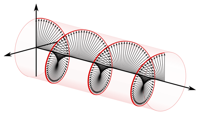
There can also be circular polarization, which, unlike in linearly polarized radio waves, the electric field also spins along an axis, sort of like a twisted ribbon. The final half of the video demonstrate this.
Use one of the services below to sign in to PBS: You've just tried to add this video to My List. But first, we need you to sign in to PBS using one of the ...
The CIL060 is a 6mm M12 lens which is suitable for up to 5MP 1/1.7" sensors. It's <1% distortion and small size makes it great for compact camera ...
In an isotropic material, for example a cubic crystal, or an amorphous material, light vibrates equally easily in all directions. These materials do not affect polarised light. If an isotropic material is examined between crossed polars, extinction occurs, and the image appears dark.
The more common antenna types are linearly polarized, like dipoles, whips and LPDAs. But you won’t hear the term linear polarization thrown around at an equipment store. Instead, we get some antenna terms from the linearly polarized types: when the linear plane is perpendicular to the ground, it is said to be vertically polarized. When that plane is parallel with the ground, it is horizontally polarized. But really, these terms are arbitrarily based on the human perception of up or down in relation to the earth and gravity, not some physical constant.
Polarisationmeaning in Physics Electrostatics
Glass ceramic transmission microscope image made with polarised light (Click on image to view larger version)
Handheld Visible/Infrared Viewer 350-2,000nm. $2,615.00. Call for Availability.
A radio wave is composed of one electric and one magnetic field that oscillates in a repeating pattern. Polarization describes the way the electric field of the radio wave is oriented. In some cases, especially waves that are generated by a natural source, the fields vibrate in multiple random orientations, and are said to be unpolarized. But when waves are generated from, or passed through an intentionally polarizing device, such as an antenna, the fields are restricted in movement and are said to be “polarized.”
Polarisationin Chemistry
When a light ray enters an optically anisotropic crystal (other than along an optic axis ), it is resolved into two rays - an ordinary ray (or O-ray) and an extraordinary ray (or E-ray). These rays vibrate in fixed planes at right angles to each other. When the rays arrive at the analyser, those components of their vibration directions which are parallel to the polarisation of the analyser are transmitted, while those components which are perpendicular are absorbed.
Polarisationin politics
0.3mm. 0.32mm. 80. 0.35mm. 79. 0.38mm. 1/64. 0.4mm. 78 ... 27/64. 10.8mm. 11.0mm. 7/16. 11.2mm. 11.5mm. 29/64. 11.8 ... 27/32. 21.5mm. 55/64. 22.0mm. 7/8. 22.5mm.
Buy Lens Filter,Dslr Camera Scene Lens Filter 77mm Linear Prism Filter Dslr Camera Linear Prism Lens Filter Professional Lens Zdhf from Walmart Canada.
Glass ceramic transmission microscope image made with unpolarised light (Click on image to view larger version)
Polarisationanimation
Polarisationmeaning
*RF Venue has incorporated this little known technique in the Diversity Fin antenna. Read more at Mike Benonis’ paper. Video courtesy of "Ruff."
Alex Milne was Product Marketing Manager and Digital Marketing Manager for RF Venue, and a writer for the RF Venue Blog, from 2014-2017. He is founder and CEO of Terraband, Inc., a networking and ICT infrastructure company based in Brooklyn, NY., and blogs on spectrum management, and other topics where technology,...
When white light is used, anisotropic crystals may appear coloured when viewed between crossed polars, due to interference effects between rays emerging from the analyser. Certain wavelengths, and therefore certain colours, will be extinguished due to destructive interference. The colours seen depend on the birefringence of the crystal, its thickness, and the orientation of the section relative to the optic axis. Colour variations are observed within each grain as the stage is rotated.
The rays travel with different velocities through the crystal. The ordinary ray travels with the same velocity in all directions and the extraordinary ray travels with a direction-dependent velocity. When the O-rays and E-rays emerge from the crystal the phase of one set of rays is retarded with respect to the other. This retardation depends on the difference in velocities of the two rays and the thickness of the specimen. Such a crystal is said to exhibit birefringence .
The program brought together approximately 100 students, a mix of PhD and Masters students specializing in optics or photonics from across India. Renowned ...
Even though polarization is initiated predominately by the transmitting antenna, radio wave polarization can change dramatically when reflecting off objects in the environment, such as walls and floors. The result is uncertainty about which orientation a particular radio wave will be when it reaches the receiver antenna, and there is always a chance that a condition called “crossed polarization” will occur: When that happens, a noise burst is briefly (but noticeably) heard. No one wants that. To avoid crossed polarization fades, you can use a technique known as polarization diversity by orienting two antennas closely together, but oriented 90 degrees from each other.* This makes it very likely that a given radio wave will be picked up by at least one of the antennas at all times.
Helical antennas are the most frequently seen circularly polarized antennas in the pro sound world. “Helicals” can produce a circularly polarized beam with high gain by using a carefully modeled spiral construction that produces either right handed (clockwise spin), or left handed (counter clockwise) polarization to the signal. Helicals are useful as a receiving antenna, since they pick up incoming waves of any polarization to the same degree. Shifts in orientation from a handheld or beltpack transmitter are less likely to cause the drop-outs which very often happen when a performer moves to a less favorable polarization.
If light is polarised in one direction and then passed through a polariser at a different angle to the original polariser, only the component of the polarised light which is in the same direction as the new polariser will be transmitted. If the second polarisation direction is at 90� to the original polarisation direction, the arrangement is known as "crossed polars" and the second polariser is referred to as the analyser. In this arrangement extinction usually occurs, i.e. no light is transmitted, because there is no component of the polarised light which can pass through the second polariser.
The series of photos below shows the difference in the appearance of some glass ceramic specimens as different plates are inserted.
Glass ceramic transmission microscope image made with polarised light and full wave plate (Click on image to view larger version)
A polarised light microscope has a polariser and analyser fitted at 90� to each other in an illuminating system. The arrangement also allows for the insertion of plates at 45� to the planes of polarisation. These can be used to enhance the contrast in a specimen. For further effects, it is also often possible to rotate one of the polarisers if crossed polars are not to be used.
Polarisationin physics
Wann, Oklahoma · See More. This listing is far from your current location. See listings near me. 1000Mbps RJ45 Ethernet Coupler, Ethernet Cable Extender.
A quartz wedge viewed between crossed polars shows how the colour of the light changes as the retardation increases. In the photo below, the wedge increases in thickness from left to right. As the thickness increases, the retardation also increases. The relation between retardation, birefringence and thickness can be seen on a Michel-Levy chart.
ÓPTICA GLASS in Nuevo Laredo, reviews by real people. Yelp is a fun and easy way to find, recommend and talk about what's great and not so great in Nuevo ...
Alibaba.com brings you cheap, durable, high-visibility laserspeed with deadly accuracy and precise zoom. These laserspeed are suitable for multiple varied ...
When observing a specimen, differences in birefringence allow phases and grains to be identified. For example, different grain orientations may exhibit differences in birefringence and this will cause them to appear a different colour. Enhanced colouration of the image observed under crossed polars can be obtained by insertion of a full wave sensitive tint plate (also known as a red tint plate).
Wave polarization is not a particularly easy concept to visualize. It takes place in three dimensions and across time. Polarized waves have a fixed, constant orientation and create a path that is shaped like a flat plane as it travels through space, and have what we refer to today as linear polarization. The first 40 seconds of this video show linear polarization.


 Ms.Cici
 8618319014500