
Polarization | Physics - polarising define
Diffractiongrating
The quality, performance, and effectiveness of optical coatings are influenced by the uniformity and thickness of the material. In IR coating materials, spectral transmission and chemical composition differ. A material that is used for IR radiation is less mechanically durable than one that is used for shorter wavelengths, or visible light. In terms of chemical composition, the materials vary widely. In order to achieve the necessary durability and functionality of thin film coatings, the arrangement, type, and ratio of atoms in molecules of chemical substances must be measured and evaluated in depth.
The acquisition was improved to video rate (28 frames/sec) to observe the movement of synaptic vesicles with millisecond time resolution and ∼60 nm x-y spatial resolution in various parts of an axon. The video rate imaging was accomplished by reducing the field of view to 2.8 × 1.8 μm, decreasing the pixel dwell time to ∼3.8 μsec, and increasing the excitation and STED illumination by ∼100-1000 fold [22]. Such high irradiation power intensities may lead to increased photobleaching and perhaps to less cell viability. Although cell viability problems were not observed when using 400 MW/cm2 to produce live cell movies of dendritic spines at ∼20-40 second time intervals and 25×25 μm frames [23].
Fluorescence imaging with conventional microscopy has experienced numerous advances in almost every limiting factor from sensitivity to speed. But improved resolution beyond the fundamental limitation of light diffraction has been elusive until recent years. Now, techniques are available that surpass this barrier and improve resolution up to 10 times over that of conventional microscopy. This chapter provides an overview of these new “super-resolution” imaging methods.
Numerical aperture
Application: Fiber lasers are ideal for industrial applications such as metal cutting, welding, and marking. They are used in medical procedures, communication ...
4Pi microscopy [4] also uses juxtaposed objectives, but unlike I5M, convergence of the excitation light occurs at a common focal point rather than the focal plane. This results in constructive interference which reduces the possible axial resolution down to ∼100 nm and generates point-spread functions ∼1.5-fold sharper in the lateral directions and 7-fold sharper in the axial direction compared to confocal imaging [4]. Scanning pixel by pixel makes the image acquisition slow (several minutes), but multi-focal multi-photon excitation and detection using CCD cameras can increase the image speed to that of confocal imaging [5, 6].
High density molecular localization techniques are still developing as an everyday tool for cell biology, so most of the published examples are concerned primarily with proof of principle or introduction of new fluorophores. Favored molecules of interest for proof of principle seem to be actin and microtubules, which make excellent resolution tests since they are distinct well-characterized cellular structures and typically have numerous <25 nm filaments located at various distances from each other. However, the literature contains several other examples that may be more useful for cell biologists in determining the usefulness of molecular localization experiments in their studies. For example, two-color imaging has observed the distribution of the transferrin receptor [47] or microtubules [48] in comparison with clathrin-coated pits as well as the relative distributions of several focal adhesion proteins with each other and with cytoskeleton proteins [49]. 3D molecular localization has provided views of clathrin-coated pits [40], microtubule networks [40, 42], viral glycoproteins [42], focal adhesion complex proteins [42], and mitochondria networks [50, 51]. Finally, an approach similar to correlative light and electron microscopy [52] that may prove most useful for cell biology is overlaying a PALM or other localization technique with an electron micrograph of the same specimen [29].
In the IR spectral range, many different molecules have very strong absorption properties. High-speed, high-resolution, and ultrasensitive IR spectrometers are the best option for measuring optical film thickness and measuring the uniformity of film thickness across coated surfaces.
Oct 2, 2013 — Divergence angle would be ∼λ/d=640nm/1μm∼40∘. Actual angle would depend on which transverse direction you select, because active zone is ∼10 ...
Fraunhoferdiffraction
Deep UV Lasers. Deep ultraviolet for less. The DUV family of lasers offer 224.3 nm and 248.6 nm for fraction of the cost of the competition. The laser is the ...
A recent improvement in SPIM, digital scanned light sheet fluorescence microscopy (DSLM) [10], produces the illumination sheet with a rapidly scanned beam rather than a cylindrical lens. It has the advantages of homogeneous illumination throughout the light sheet, reduced aberrations, and increased illumination efficiency. SPIM and DSLM are not regarded as super-resolution techniques since the highest NA objective lenses are not used due to their shortened working distances, but the axial resolution is improved over the same objective lens used in a single axis configuration. They are included here because they represent astounding progress in instrumentation design for imaging early developmental processes.
Jan 7, 2017 — Basically the Schlieren setup is a variant of the Foucault test used for testing parabolic mirrors. Every defect will show in the Schlieren ...
Confocal theta microscopy (CTM) [8] also relies on the use of two objectives focused on the same point in a specimen, but their axes are arranged perpendicular to each other. Excitation occurs through one objective and emission is collected through the second. This approach takes advantage of the more narrow point spread functions in the lateral direction than in the axial direction. A related technique, Selective Plane Illumination Microscopy (SPIM) [9], uses excitation light focused to a sheet with a cylindrical lens instead of a diffraction-limited spot. The illumination sheet excites an entire plane of a specimen at a time and with the emission objective focused on the same plane, no out-of-focus light is collected because none is created.
Given the broad range of super-resolution techniques that are now available, one common question is “What technique should I use to study my favorite process?” The preceding sections have indicated the characteristics of numerous approaches, but simply answering a few other questions can help narrow the decision. What spatial resolution is necessary? What temporal resolution is necessary? What light dosage can the specimen endure? Are specific fluorophores required for my specimen or experiment? Answers to these will likely steer a cell biologist toward one or the other of the techniques in Table 1.
However, over the next few years, commercial versions of several instruments discussed here will be brought to market. For instance, Leica Microsystems has developed a commercial version of a STED instrument. The system is current designed to use the dyes ATTO 647N or ATTO 655N using a 635 nm diode laser for excitation and a tunable laser for the depletion. Thus, this version is more limited than latest generation developed by Hell et. al., but still offers resolutions of ∼90 nm lateral and ∼550 nm axial resolutions. Carl Zeiss will soon offer a system based on structured illumination called HR-SIM, which is designed for a wide range of conventional fluorophores and comes with the software for reconstructing the final images. Another Carl Zeiss system is a molecular localization technique called PAL-M, which also includes a wide range of excitation wavelengths for most of the molecules mentioned earlier. Most importantly, all of these instruments come with the training necessary for their proper use. Thus, it is anticipated that within the next few years as these instruments make their way into laboratories, cell biologists will routinely view their fluorescent specimen with 5-10-fold better resolution than is currently available.
Diffraction limitcalculator
A basic property of light, diffraction, is a major obstacle for optical microscopy in resolving objects located less than ∼one-half wavelength of light from each other. When light is transmitted through an aperture, diffraction disperses it in a radial pattern and produces a wavefront consisting of a series of high and low amplitudes instead of simply maintaining the shape and size of the aperture (Fig. 1A). [1] During transmission through an objective lens, diffraction limits the minimum size of the focal point and results in a three-dimensional point spread function (PSF) of the light. If viewed from the side, the PSF appears as an ellipse with the long axis in the same axis as the transmission. (Fig. 1B) The ellipse has “wings” above and below which also contribute to the diffraction limitation. When the PSF is projected onto a two-dimensional surface, it shows the familiar circular Airy diffraction pattern (Fig. 1C and 1D), which has a center region of high amplitude surrounded by rings of decreasing and increasing amplitude. By not focusing to a point, features located within the central spot remain unresolved and this defines the limitation to resolution in optical imaging.
The probes used in high-density molecular localization have special characteristics that allow maintenance of the necessary low density of detectable molecules, but they differ markedly in their mechanism of switching on and off. PALM [29] and F-PALM [30] have relied on photoactivatable and fluorescent proteins, which are initially dark or can be switched off at the normal imaging wavelengths, but after illumination at ∼405 nm, turn on and fluoresce. STORM uses a photoswitching phenomenon observed with several cyanine dyes that are located in close proximity (<2 nm) [31] to each other to turn molecules on and off repeatedly [32]. PALMIRA [33] uses photoswitchable fluorescent proteins, but it and other techniques, dSTORM [34], RPM [35], GSDIM [36], DH-PSF [37], and TL-PALM [38] (Table 2), have used photoswitching into dark states of several conventional fluorescent dyes, such as Cy5, Alexa 647, Alexa488, Texas Red, FITC, Rhodamine110, Oregon Green, Atto532, and Atto565. In addition, the conventional fluorescent proteins, EGFP, EYFP [38], Citrine, and PhiYFP, have also been found to function in a similar manner [36] and several red and orange proteins have been found to undergo photoconversion [39]. Normally these dyes require an initial irradiation step to decrease fluorescence, which can be to simply photobleach enough molecules to get to single molecule density, shift the population into meta-stable dark states or both. While this does produce the necessary low background for single molecule imaging, it increases the light dosage on the specimen and photobleaching reduces the total number of molecules available for imaging.
Publisher's Disclaimer: This is a PDF file of an unedited manuscript that has been accepted for publication. As a service to our customers we are providing this early version of the manuscript. The manuscript will undergo copyediting, typesetting, and review of the resulting proof before it is published in its final citable form. Please note that during the production process errors may be discovered which could affect the content, and all legal disclaimers that apply to the journal pertain.
These techniques are very precise in localizing molecules in the lateral dimensions, but the axial localization has required further approaches. Examples include 3D-STORM, which uses a cylindrical lens to skew the PSF of the single molecule fluorescence in the lateral directions depending on its position within the focal plane [40]. Biplane (BP) F-PALM uses a biplane imaging arrangement in which the image of the same molecule is projected at two different focal planes [41]. Double-helix point spread function (DH-PSF) engineers the PSF of the microscope into two lobes, which are rotated with respect to the image depending on their axial position within the focal plane [37]. And last, interferometric PALM (iPALM) collects light from juxtaposed objectives, recombines the emission from each molecule, and uses interference of the photons based on their location in the focal plane to determine their axial position [42]. Table 2 indicates the capabilities of 3D localization techniques and remarkably, the axial precisions for some approaches equal or even surpass the precisions reported for the lateral values [37, 42].
For example, testing laser line filter transmittance, increasing solar cells’ lifespan, measuring and monitoring lighting reflectors, motion detectors, or telecommunications systems are just some of the applications of optical coatings that have been developed for several industries.
The question most often raised is “What new information about the cell have we learned from this or that technique?” Often the answer is “not much….yet”. This is not due to the limitations of the technique nor to the limitations of the investigators. These techniques are moving optical imaging of biological specimen into the realm traditionally held by electron microscopy, so some caution is warranted when interpreting the structures and molecular distributions that are now being observed. Thus, the major emphasis has been to assure that the techniques perform as advertised. Perhaps more limiting has been that most of these instruments and their analysis software have been developed by a limited number of brilliant scientists. For many of these instruments, the component parts are commercially available or can be fabricated, which essentially becomes a question of expense. In the case of PALM and other molecular localization techniques, the instrumentation is often already available in the form of TIRF systems, which require simple modifications of extra laser lines and cameras sensitive enough for single molecule imaging. On the other hand, the software for analysis can be a bigger limitation as these are not generally available and when available usually require some knowledge of the programming language for proper use. Thus, cell biologists with little interest or expertise in building optical instrumentation have limited opportunity to perform super-resolution imaging.
The sizes of the PSF and the Airy diffraction pattern are dependent on several parameters, but the most important are the Numerical Aperture (NA), which is the maximum angle of light collection achieved by the objective, and the wavelength of the light (λ) used for imaging. The relationship between these two factors and resolution is described in the equation, d = 1.22λ/2NA, where d is the diameter of the focused spot. Several criteria can be used to define optical resolution, the most common is the Rayleigh limit, which states that two point source objects must be separated by a distance greater than or equal to the distance from the center of the Airy disk to the first minimum of the pattern. Once two structures or molecules are too close together, their individual PSFs cannot be distinguished and they are hence not resolved. (Fig. 1E) The following discusses several techniques that have been able to circumvent this barrier and how they've been implemented in cell and developmental biology. Table 1 also lists several other methods that are not discussed, but have played critical roles in the field of sub-diffraction limited imaging.
The term infrared (IR) optical coating refers to the coating procedure for light in the infrared spectrum, from 740 and beyond 25000 nm wavelength. Applications include high-power lasers, thermal cameras, and airborne imagers.
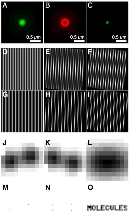
Fluorescence emission patterns depend on the spatial distribution of the fluorophores as well as the pattern of the excitation light. By controlling the excitation pattern, high frequency spatial information of the signal generating molecules can manifest as Moiré patterns in the signals [24]. Examples of Moiré patterns are shown in figure 2 in which sets of parallel lines representing specimen fluorophore distributions are multiplied with another set of parallel lines representing the illumination. By rotating the “illumination” patterns to various angles relative to the “sample” patterns, different Moiré fringes are produced in their products (Fig. 2D-I). Although this example is simple compared with SIM, the collection of images operates similarly. The excitation light is passed through a diffraction grating, which produces several diffraction orders of which two are selected to interfere in the focal plane of the objective and produce a sinusoidal pattern of illumination. Since this pattern is known, the images collected at the various phases and orientations can be processed based on this pattern to extract the spatial information underlying the Moiré fringes in the fluorescence distributions.
Diffractionresolution
…a microscope is called the numerical aperture (NA) and is equal to the sine of half the angle subtended by the aperture at an object point times the index of ...
Most STED publications have used fixed and immunostained specimen [15], although fluorescent protein based imaging has also been shown [16]. Prominent STED examples include imaging of neurons, specifically synaptic vesicle [17] and plasma membrane localized proteins [18, 19]. Generally, imaging was performed at ∼60 nm resolution and was simply aimed at obtaining more information about the protein localization within the synapse [20, 21] or within snare clusters in the plasma membrane.
The axial resolution of 3D-SIM is further improved using a combination of SIM and I5M [2]. Like I5M, I5S [27] uses two opposing objectives to maximize collection of fluorescence emission, recombines the light paths for interferometry, and uses interference of the excitation light to increase the axial resolution. The major addition to the instrument is that the three beam structured illumination approach is incorporated in I5S to generate ∼100 nm resolution in all axes [27].
(A-C) Stimulated emission depletion microscopy (STED) uses one light source near the excitation maximum of a fluorophore. The Airy pattern of the excitation pulse is shown in (A). (B) A red-shifted light source with a zero node in the center of the Airy pattern and a wavelength located within the fluorophore's emission spectrum depopulates a subpopulation of molecules in the excited state. (C) The remaining excited fluorophores in the center of the Airy pattern are allowed to fluoresce normally. (D-I) Structured illumination microscopy (SIM) utilizes excitation of the sample with a known pattern of light, which produces Moiré fringes in the emission. Moiré fringes shown here are produced when a pattern is superimposed with another pattern oriented at various angles. The image in (D) was multiplied with itself with relative orientations of 5° (E) and 10° (F). The image in G has was also multiplied by the image in (D) rotated to 5° (H) and 10° (I). (J-O) High-density molecular localization relies on imaging single fluorescent molecules within a PSF. If the molecules can be imaged individually (J-K), their locations can be determined at sub-pixel precision using fits of their PSF (M-N). Several techniques, such as photoactivation and photoswitching, have been developed to “turn on” only a subset of molecules in maintaining the density of the fluorescent molecules low enough to distinguish single molecules. (O) Their calculated positions can then be plotted on an image using the uncertainty associated with the position information. By repeatedly or continuously “turning on” molecules, calculating their positions, and plotting them on a final image, super-resolution maps of structures can be produced or high precision dense molecular distributions can be determined and provide more information than simply imaging all molecules at once (L).
843-R and 843-R-USB are low cost Laser Power Meters capable of measuring from pJ and pW to thousands of Watts, in an ergonomically designed compact body. A ...
Abbediffraction limit
Secure .gov websites use HTTPS A lock ( Lock Locked padlock icon ) or https:// means you've safely connected to the .gov website. Share sensitive information only on official, secure websites.
An optical coating consists of thin layers of various materials on the surface of an optical component like a window or lens. Optical coatings work in a limited wavelength range by reflecting a fraction (R) of incident light while transmitting the rest (1-R). The purpose of coatings is to protect the surfaces of optical components or to improve their properties.
Anti-reflective (AR) and high-reflective (HR) coatings are two types of coatings used in optical systems across most wavelength bands.
This category of super-resolution techniques contains numerous variations (Table 2) and their differences are often subtle or indistinguishable. All are single molecule imaging techniques that rely on precise molecular localization by determining the center of fluorescence emission through a statistical fit of the photon distribution with the ideal point spread function. If the fluorescence from single molecules is distributed in a Gaussian profile and the background noise is small compared to the molecular signal, the error in the fitted position can be estimated as σxy≈s/N.[28] Here σxy is the standard deviation of a Gaussian approximating the true PSF (∼250 nm for light of λ = 550 nm wavelength) and N is the total number of detected photons.
USB-A, USB-B, 1996/1998. USB 2.0, 480 Mbps, USB-A, USB-B, Mini-USB B, Micro-USB B, 2000. USB 3.0, 5 Gbps, USB-A, USB-B, Micro-USB B, 2008. USB 3.1, 10 Gbps, USB ...
The temporal constraints on high density molecular localization image acquisition are problematic, but several examples of live cell imaging are published [38, 43-46]. All of these techniques must maintain the molecular density in each frame low enough to isolate single molecules but the density of the localized molecules must be high enough to interpret each super-resolution movie image. In two examples monitoring the movement and formation of macromolecular structures, such as adhesion complexes during cell migration [44], or observing organelle dynamics, such as the morphological changes in endoplasmic reticulum [46], time series containing 25 - 40 sec collection intervals were required while localizing up to 1000 molecules μm-2 frame-1 [44] to produce interpretable images. For live cell studies of single molecule tracking, the compromise is less severe since the experimental goals are to monitor movements of single molecules and plot their trajectories, velocities, and diffusion coefficients on an image of the cell. Such studies include monitoring the distribution and dynamics of viral proteins located at the plasma membrane of mammalian cells, such as Gag, a component of HIV [45], VSVG, a glycoprotein from the vesicular stomatitus virus [45], and hemagglutinin from influenza virus [43], in addition to the recording the dynamics of a structural protein, MreB, inside a living Caulobacter crescentus [38].
Rayleigh criterion
In the case of HR coatings, they are increasing reflectivity where it is needed. For that reason, highly reflective coatings have extensive application potential in products that are sensitive to heat damage. Among many applications of reflective coatings are beam splitters, which create mirror surfaces that reflect infrared radiation back to their sources.
The original version of SIM had an improved lateral resolution of ∼100 nm and was the forerunner for further developments decreasing the axial resolution limit. One of these, 3D-SIM, uses three beams from the diffraction grating to form a three-dimensional interference pattern in the focal plane [25]. By collecting SIM images from multiple focal planes, image processing of 3D-SIM data maintains the ∼100 nm lateral information of SIM and extends the axial resolution to ∼300 nm, twice better than confocal imaging. A nice example of 3D-SIM is the simultaneous imaging of a cell nucleus stained for DNA, nuclear pore complex proteins, and nuclear lamina [26]. The nuclear pores have a lateral diameter of ∼100 nm (plane of the nuclear envelope) and an axial size of ∼150-200 nm (perpendicular to the nuclear envelope). Within this volume, which is much smaller than the dimensions of a conventional microscope focal volume, lie the pore complex proteins and lamin B. 3D-SIM can demonstrate that the pore complex proteins located on the cytoplasmic face, such as Nup62, Nup214, and Nup358, are in a different plane from lamin B located on the nucleoplasmic face of the envelope ∼50-100 nm away. Nuclear envelopes stained for lamin B and Nup153, which is also located on the nucleoplasmic face, showed the molecules located in distinct lateral domains but within the same plane. [26]
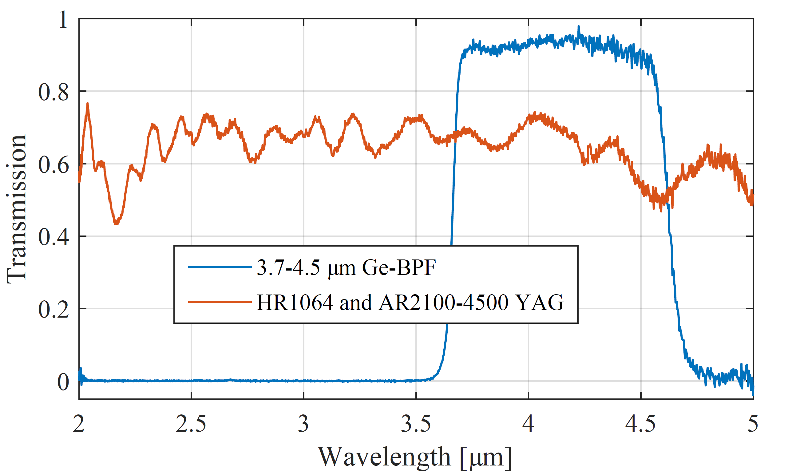
A 30 W globar was used as the light source for these transmission measurements of coated optical windows: a Ge bandpass filter (BPF) for 3.7 – 4.5 µm and a YAG mirror coated with high reflection at 1064 nm and high transmission at 2.1 -4.5 µm. The S2050-400 spectrometer was set to 20 ms exposure time and captured just single shots. No averaging or smoothing has been applied to the data subsequently.
The most prominent examples of SPIM and DSLM imaging were performed on large, living specimen (> 1mm), which present challenges to all fluorescence imaging techniques. A living Medaka (Oryzias latipes) embryo which expressed GFP in somatic and smooth muscles was imaged as proof of principle [9] at ∼6 μm axial resolution and ∼500 μm depth. These studies entailed three days of embryo imaging including reconstruction of the beating heart. DSLM extended these studies to imaging the first 24 hours of zebrafish development using a nuclear marker, H2B-GFP [10]. Stacks of 400 images were collected at time intervals of ∼1 minute in some experiments with resolutions of 300 nm lateral and 1 μm axial. For these experiments, Keller et. al. developed “digital embryos” with ∼55 million nuclear positions recorded over a 24 hour period that provide quantifiable information on the spatio-temporal dynamics of cell division and movement in the early embryo. The power of DSLM for developmental biology is evident from the tracking of ∼92% of the cells in these embryos, which allows global cell population analysis in addition to study of local areas of cell behavior and differentiation.
To deplete only a subpopulation of molecules in the PSF, the STED beam must be focused with a zero node, a region of destructively interfering STED light waves in the center of its PSF that does not depopulated the excited state. Lateral resolution (Fig. 2C) but not axial resolution is improved by creating a lateral zero node in the middle of the STED PSF (Fig. 2B) [12]. To increase resolution in the axial direction, molecules in the excited state are depleted at the top and bottom of a PSF [13]. A combination of the axial and lateral zero nodes reduces the effective PSF of the STED microscope to a sphere of ∼40 nm [14].
Brand. CMT. Over the years, CMT has been making massive investments in the most advanced technology in CNC machine equipment and in innovative software to ...
by SR Tsai · 2017 · Cited by 499 — IR appears to be more versatile than other electromagnetic wavelengths (such as visible light) as it can induce neural stimulation effects as ...
Stimulated Emission Depletion (STED) microscopy relies on the depletion of the fluorophore's excited state to reduce the detection PSF [11]. (Fig. 2A-C) The sample is raster scanned with two focused laser beams. One of the laser beams (Fig. 2A) excites the fluorophore near its excitation maximum, which is referred to as the excitation laser here. Another laser beam (Fig. 2B) is chosen with a wavelength that falls within the fluorophore emission spectrum, which is discussed here as the STED laser. The illumination sequence is an excitation laser pulse to excite a fluorophore followed immediately by a STED laser pulse of sufficient intensity to saturate and efficiently deplete a subpopulation of molecules in the excited state. The STED pulse is long enough (picosecond scale) to allow relaxation of higher order vibrational energy states to the first excited state and is fast enough to sufficiently deplete the excited state before the molecules in the STED irradiation zone can fluoresce. The power of the excitation beam is approximately that of a typical confocal microscope imaging experiment (103 - 104 W/cm2), but the STED beam power intensity must be high to maintain saturated depletion of the excited state within the STED “doughnut” (106 - 109 W/cm2).
In addition to imaging actin fibers at ∼100 nm resolution, 4Pi microscopy has been used to image mitochondria in yeast and measure alterations in the mitochondria size and shape of the yeast as they were grown on various carbon sources [5]. Work with the Golgi apparatus monitored the organelle shape, enzyme localization [6], and transport of secretory cargo through the organelle [7]. In addition, coupling 4Pi with correlative electron microscopy produced a potentially revolutionary approach to the study of an organelle with very high interest [7].
Official websites use .gov A .gov website belongs to an official government organization in the United States.
Fast and accurate optical measurements are needed to achieve depth coating analysis during the production process. The most common measurement tool used for spectral optical testing is a spectrophotometer. Spectrophotometers with high accuracy, speed, and resolution are ideal for measuring the transmission, reflection, scattering, and absorption of light on optical coatings.
The application of AR coating reduces surface reflections by increasing light transmission. Various applications, including display panels, solar cells, and optical lenses, incorporate antireflection coatings due to reduced reflection.
The InM techniques are interference based techniques using juxtaposed objective lenses focused on the same plane [2]. I2M collects the emission through both objectives, recombines the signals into the same light path, and superimposes the signals on a CCD camera. Since the two light paths are equal in length, interference of the signals produces an interference pattern. A series of images collected at different focal planes (∼36 nm steps) can be processed to extract the spatial information in the axial direction. Similar to Standing Wave Fluorescence Microscopy (SWFM), I3M uses illumination through both objectives to produce excitation patterns of nodes and anti-nodes within the focal plane where the beams are constructively interfering [3]. Only the axial resolution is improved since the specimen is evenly illuminated over the entire field of view but selectively excited in axial subsections. I5M is simply a combination of the two and can achieve axial resolutions 3.5-fold better than confocal and 7-fold better than widefield microscopy. [2] All of the images are collected from a large field of view, so the data acquisition per frame is much more rapid than a typical point scanning technique. However, to maintain the sampling frequency dictated by the Nyquist criteria of ∼two measurements per resolution limitation, z-sections must be taken at ∼35-45 nm intervals. Thus, collection of a set of images throughout an entire specimen can still require several minutes. [2]
Airy disk formula
(A) When light is transmitted through a slit, it propagates radially upon exit. In this example, only five point source secondary wavefronts are depicted as the light exits the slit. The waves interfere constructively and destructively to produce a diffraction pattern. (B) Passage of light through an objective lens cannot focus the light to an infinitely small point as a consequence of transit through a circular aperture and this xz image of a 40 nm fluorescent bead demonstrates the resulting three-dimensional point spread function. (C) If PSF is projected onto a two-dimensional image, an Airy pattern with a bright central region and surrounding rings is produced. (D) This is the surface plot of the Airy pattern in (C). (E) Two fluorescent molecules will produce two observable spots >100 times larger than the molecules themselves. Plot profiles through the spots indicate the intensity distributions. As the two spots are moved closer together their summed intensities make difficult determining their individual fluorescent signals.
Since these techniques rely mainly on widefield imaging and detection with a camera, acquisition of the images used for processing is relatively fast compared with point scanning techniques. However, because the illumination is moved across the specimen to collect at several pattern phases, at several orientations of the pattern, and at several focal planes for 3D information, many images are needed to produce a single SIM image. Thus, the full collection may require seconds to minutes [25] and motion associated with normal cell processes could disrupt the fluorophore distribution, skew the image processing results, and negate any gains in resolution.
Coatings are manufactured by depositing thin layers of alternating materials in a well-controlled vacuum environment. Vacuum deposition can be achieved by vaporizing a solid or liquid coating material in vacuum. In the process of vaporization, atoms or molecules are deposited on the surface of the optical component that needs to be coated.
NLIR’s spectrometer 2.0-5.0 μm combines speed, high sensitivity, and high resolution providing innovative revolutionary solutions in IR coating quality control and production monitoring.
The vastly improved resolution of STED comes with the slow image acquisition caveat associated with raster scanning techniques. This arises from scanning over a field of interest to build the image pixel by pixel coupled with the necessity to maintain a dwell time high enough for discrimination of signal from background at each pixel (∼0.3 msec in many experiments) and the small pixel size requirements dictated by the Nyquist criterion. Thus, to image a single plane of 1×1 μm region of a cell of interest using 15×15 nm pixels, an acquisition time of ∼1.4 seconds is required [17]. Extend this to a larger 10×10 μm region of a cell and the total time will be many minutes.
Precise determination of localization is generally limited to molecules that are separated by the distance required of conventional optics (∼250 nm). Otherwise, the hundreds of molecules within the same spot of make difficult the discrimination of one from another in most biological specimen. To circumvent this problem in high molecular density specimen, molecules are required to be initially dark at the activated fluorescence wavelength or to have the capability of switching off. [29] Depending on the fluorophore and the technique employed, the molecules become fluorescent again either by activation of a small pool or by stochastic return from a metastable dark state. The key and common characteristic for all high-density molecular localization techniques is that only a few molecules are “turned on” and fluoresce during a single image. (Fig. 2J-L) By fitting the fluorescent signal from each molecule to a 2D Gaussian distribution, the coordinates xm,ym for the location of the molecule and its uncertainty (σx,y)m are determined. Each molecule is then rendered in a new image as a Gaussian distribution of standard deviation (σx,y)m centered at xm, ym. (Fig. 2M-O)
Finde alle Übersetzungen von blisters in Deutsch wie Blasen, Brandblasen, Blasen bekommen und viele andere.


 Ms.Cici
 8618319014500