
Polarization of Light | Olympus LS - polarized light examples
This shows the intensity curves for the radial distribution of the diffracted light for different separations. Your eye sees the characteristic bullseye distribution of light as illustrated below. While perfect imaging of the source would be smaller perfect circles of light, this shows the smearing of the light by diffraction into the bullseye patterns. For modern digital photography where the images are projected onto a CCD, the information is collected on pixels of the digital detector. At left is an attempt to show the effect of diffraction on such imaging in cases where the diffraction is the phenomenon that limits the resolution. If the image is in focus and free of visible affects of lens aberrations, then it may be that it will fit on one pixel. But if the aperture is small enough, then diffraction can spread the image onto neighboring pixels and constitute the limit on the resolution of the image. References: The Cambridge in Colour site has calculations and demonstrations of diffraction spreading at different f-numbers.
Diffractionresolution
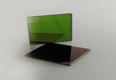
ZnSe is a kind of chemically inert material with high purity, strong adaptability and easy processing. It has low optical transmission loss and good transmittance. With low absorption coefficient and high resistance to thermal shock, it is the preferred material for high-power CO2 laser optical elements.
ZnSe is a kind of chemically inert material with high purity, strong adaptability and easy processing. It has low optical transmission loss and good transmittance. With low absorption coefficient and high resistance to thermal shock, it is the preferred material for high-power CO2 laser optical elements. Because of the uniform and consistent refractive index of the infrared material, it is also an ideal material for the protection window and optical elements of the forward-looking infrared thermal imaging system. At the same time, the material is also widely used in medical and industrial thermal radiation measurement systems and infrared spectrometer species of Windows and lenses. ZnSe is a scratch and soft material, not suitable for harsh environment.
Abbediffraction limit
For modern digital photography where the images are projected onto a CCD, the information is collected on pixels of the digital detector. At left is an attempt to show the effect of diffraction on such imaging in cases where the diffraction is the phenomenon that limits the resolution. If the image is in focus and free of visible affects of lens aberrations, then it may be that it will fit on one pixel. But if the aperture is small enough, then diffraction can spread the image onto neighboring pixels and constitute the limit on the resolution of the image.
ECOPTIK using USA import CVD material, material has no impurity absorption, scattering loss is very low. Therefore, become the preferred materials for optical device fabrication of high-power CO2 laser system. In addition, in the whole transmission band, but also in the different optical systems commonly used materials.
If you are imaging two points of light, then the smallest separation at which you could discern that there are two could reasonably be used as the limit of resolution of the imaging process. Presuming that diffraction is the determining factor, then the generally accepted criterion for the minimum resolvable detail is the Rayleigh criterion. This shows the intensity curves for the radial distribution of the diffracted light for different separations. Your eye sees the characteristic bullseye distribution of light as illustrated below. While perfect imaging of the source would be smaller perfect circles of light, this shows the smearing of the light by diffraction into the bullseye patterns. For modern digital photography where the images are projected onto a CCD, the information is collected on pixels of the digital detector. At left is an attempt to show the effect of diffraction on such imaging in cases where the diffraction is the phenomenon that limits the resolution. If the image is in focus and free of visible affects of lens aberrations, then it may be that it will fit on one pixel. But if the aperture is small enough, then diffraction can spread the image onto neighboring pixels and constitute the limit on the resolution of the image. References: The Cambridge in Colour site has calculations and demonstrations of diffraction spreading at different f-numbers.
Diffraction limitcalculator
References: The Cambridge in Colour site has calculations and demonstrations of diffraction spreading at different f-numbers.
If an image is made through a small aperture, there is a point at which the resolution of the image is limited by the aperture diffraction. As a matter of general practice in photographic optics, the use of a smaller aperture (larger f-number) will give greater depth of field and a generally sharper image. But if the aperture is made too small, the effects of the diffraction will be large enough to begin to reduce that sharpness, and you have reached the point of diffraction-limited imaging.
While perfect imaging of the source would be smaller perfect circles of light, this shows the smearing of the light by diffraction into the bullseye patterns.


 Ms.Cici
 8618319014500