
Optical Transmittance of Fused Silica at Elevated ... - fused silica transmittance
Trans-Illumination: Illumination on the opposite side of the sample as the viewing apparatus. Brightfield, differential interference contrast (DIC), Dodt gradient contrast, and darkfield microscopy are some examples of imaging modalities that utilize trans-illumination.
Multispectralandhyperspectral imaging

Each of the multiple light-emitting points on the source radiate light over a range of angles. The collector lens gathers this light and transmits a beam whose maximum diameter is limited by the field stop. The light is then incident on the field lens, which forms an image of each source point at the aperture stop. The alignment of the source image at the aperture stop is critical, since the aperture stop is positioned at the front focal plane of the condenser lens.
Source light transmitted through the sample plane is imaged to the objective back focal plane, which is located between the objective and tube lenses. No image of the light source is formed on the camera sensor, which preserves image quality.
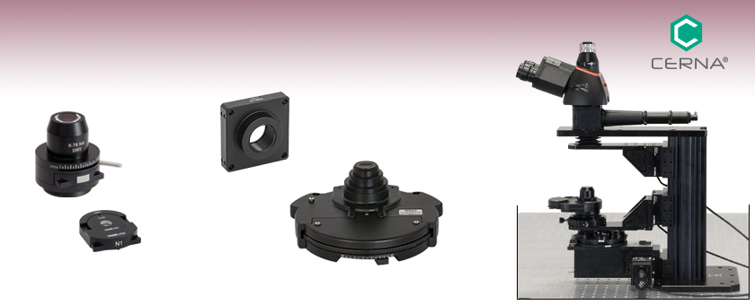
To support home-built Cerna® microscope systems, Thorlabs offers four achromatic condensers. Designed for upright microscopes, these condensers collect light emitted by an illumination source to illuminate transmissive samples from beneath the objective. They are used in several transmitted light imaging modalities, including brightfield illumination, Dodt contrast, and differential interference contrast (DIC) imaging, and have an internal turret or tray to mount one or more condenser prisms, illumination masks, and/or other optics.
Working Height: The height of the support rail of the microscope body plus the height of the base. The size of the working height, along with the throat depth, determine the working space available for microscopy.
The CSC2001 contains an internal slot that accommodates trays designed to mount various optics. Magnets in the tray and inside the slot ensure easy exchange and repeatable positioning of optics within the condenser. The CSC2001 condenser comes with one C32 tray for mounting Ø32 mm optics. Additionally, we offer the CN1 and CN2 trays for use with DIC condenser prisms and the CSM tray for mounting Ø1" optics. For tray specifications see the table below.
The CSC2001 works out-of-the-box with objectives ranging from 10X to 100X by adjusting the cone of illumination with the aperture diaphragm. For compatibility with 4X objective lenses, we offer the C4X lens, which is easily positioned within the CSC2001 using a CN1 tray (all items sold separately). For C4X specifications see the table below.
For sample viewing, Thorlabs offers trinoculars, double camera ports, and camera tubes. Light from the sample plane can be collected via cameras, photomultiplier tubes (PMTs), or custom setups using breadboard tops. Click here for additional information about viewing samples with a Cerna microscope.
The condenser's numerical aperture (NA) strongly impacts a microscope's resolution, since the angular range of the light incident on the sample affects the angular range of light transmitted or reflected by the sample. According to a general rule for optimizing resolution, the condenser NA should be as least as large as the objective NA. In other words, the cone of light provided by the condenser should have an angular range that matches or exceeds that accepted by the objective lens.
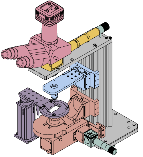
This overview was developed to provide a general understanding of a Cerna® microscope. Click on the different portions of the microscope graphic to the right or use the links below to learn how a Cerna microscope visualizes a sample.
Thorlabs manufactures many components which use dovetails to mate with our own components or those of other manufacturers. To make it easier to identify dovetail compatibility, we have developed a set of dovetail designations. The naming convention of these designations is used only by Thorlabs and not other microscope manufacturers. The table to the right lists all the dovetails Thorlabs makes, along with their key dimensions.
Trans-illumination illuminates from the opposite side of the sample as the viewing apparatus. Example imaging modalities include brightfield, differential interference contrast (DIC), Dodt gradient contrast, oblique, and darkfield microscopy. Click here for additional information on trans-illumination with Cerna.
Each monochrome image records the interaction of light (reflection and absorption) with the material of the textile and pigment at the specific bandwidth of the filter. The variation of the interaction of the light with the different bandwidths can reveal and distinguish materials. Image subtraction with image processing software such as Adobe Photoshop or ImageJ can be used to process images to better reveal some of the pigments used. Image subtraction is a simple, powerful process that can be applied for visualizing the difference or changes between two images (Jain 1986). The pixel values of two images are subtracted resulting in an image that reveals the differences between the pixel values of two images.
Multispectralcamera
Figure 3: Cones describe the light incident on a sample point from the condenser (left, gold), the light transmitted through the sample (right, yellow), and the range of light the objective can collect (right, orange). The cones' angles are measured from the optical axis. The angular ranges of the light cones incident on and transmitted by the sample are approximately the same (θcd ), since light that is not absorbed or scattered by the sample travels in an approximately straight line. The angular range (θobj ) accepted by the objective lens is can be different. The numerical apertures of the condenser (NAcd ) and objective (NAobj ) are often used to compare the angular ranges of the transmitted light to the light the objective lens can gather.
To fully exploit the information obtained by the hyperspectral imaging camera at MCI requires a sophisticated visualization and analysis software package. The work between SAO and MCI involves investigating the possibility of adapting SAOImage DS9 to support general purpose hyperspectral visualization and analysis. Bill Joye (SAO developer) and E. Keats Webb are working closely to determine the requirements for visualization and analysis, to identify which of these functions already exist within SAOImage DS9, and to determine the effort required to provide MCI (and others with similar needs) the full functionality that is required.
Fischer, C., and I. Kakoulli. "Multispectral and hyperspectral imaging technologies in conservation: current research and potential applications," Reviews in Conservation 7 (2006): 3-16.
Multispectral vs hyperspectralremote sensing
Ricciardi, P., J.K. Delaney, L. Glinsman, M. Thoury, M. Facini, and E.R. de la Rie. 2009. "Use of visible and infrared reflectance and luminescence imaging spectroscopy to study illuminated manuscripts: pigment identification and visualization of underdrawings." Proceedings of O3A: Optics for Arts, Architecture, and Archaeology II: 7391(July 2, 2009): 739106-1-12.
Since an image of the source is at the front focal plane of the condenser lens, only bundles of parallel rays are incident on the sample plane. No source image is formed at the sample and the illumination is uniform.
In order to reduce wear and simplify connections, dovetails are often machined with chamfers, recesses, and other mechanical features. Some examples of these variations are shown by the drawings below.
Köhler Illumination: A method of illumination that utilizes various optical elements to defocus and flatten the intensity of light across the field of view in the sample plane. A condenser and light collimator are necessary for this technique.
The microscope body provides the foundation of any Cerna microscope. The support rail utilizes 95 mm rails machined to a high angular tolerance to ensure an aligned optical path and perpendicularity with the optical table. The support rail height chosen (350 - 600 mm) determines the vertical range available for experiments and microscopy components. The 7.74" throat depth, or distance from the optical path to the support rail, provides a large working space for experiments. Components attach to the body by way of either a linear dovetail on the support rail, or a circular dovetail on the epi-illumination arm (on certain models). Please see the Microscope Dovetails tab or here for further details.
Note: Thorlabs does not guarantee compatibility with other industry-standard microscopes not explicitly mentioned on this webpage.
RGBvs multispectral vs hyperspectral
Alternately, the microscope can be configured so the objective both illuminates and collects light from the sample (Figure 2). In this case, there is no separate condenser lens system.
As an example, when the objective lens has a 0.7 NA with air (n = 1) between the lens and sample, the lens' angle of acceptance is θ = θobj = 44.43°. For the system illustrated in Figure 2, the NA of the illumination and the NA of the collected light are the same, since both light paths pass through the objective lens.
The Cerna microscopy platform's large working volume and system of dovetails make it straightforward to connect and position the components of the microscope. This flexibility enables simple and stable set up of a preconfigured microscope, and provides easy paths for later upgrades and modification. See below for a couple examples of the assembly of some DIY Cerna microscopes.
The Smithsonian Astrophysical Observatory (SAO) and MCI received a 2013 Smithsonian Grand Challenge Level One Grant from the Consortium for Unlocking the Mysteries of the Universe to fund Adapting SAOImage DS9 for General Purpose Hyperspectral Imaging. Members of SAO have developed extensive expertise in the visualization and analysis of complex astrophysical datasets. SAOImage DS9 is a software application developed at SAO specifically for this task and is widely used world wide by the astrophysical community. In particular, SAOImage DS9 has enhanced support for the visualization of large complex 3D datasets without the need for advanced or specialized computer hardware.
This achromatic air condenser is designed to be used with dry objectives. It is equipped with an adjustable aperture stop diaphragm that is controlled by a lever on the side, as shown in the drawing below.
hyperspectralvs.multispectralremote sensing ppt
For multiband imaging, we use a modified DSLR. Most DSLRs have IR-cut filters on the sensors that increase the quality of the visible light image by blocking any infrared radiation from the sensor. The modification of the camera we use included the removal of the IR-cut filter and the color filter array (CFA) allowing the camera to have a maximum sensitive of around 330nm to 1200nm and to acquire monochrome images.¹ The spatial resolution of this camera, 5616 x 3744 pixels, allows an entire object to be captured at a fairly high resolution in a single image. Generally the camera is mounted on a studio stand and the filters are changed manually, without changing the focus or position of the camera. Movement of the camera or focus while changing the filters manually could affect the alignment of the images. A filter wheel could be useful to avoid these small shifts, however this increases setup costs and manual changing has been adequate so far. Nine filters are used, producing nine monochrome images for each filter. The transmission curve for the filters can be seen below.
A microscope objective collects and magnifies light from the sample plane for imaging. On the Cerna microscope, the objective is threaded onto a nosepiece, which holds the objective at the throat depth, or the distance from the optical path to the support rail of the microscope body. This nosepiece is secured to a motorized focusing module, used for focusing the objective as well as for moving it out of the way for sample handling. To ensure a light-tight path from the objective, the microscope body comes with a bellows (not pictured).
Bayonet Mount: A form of mechanical attachment with tabs on the male end that fit into L-shaped slots on the female end.
Dovetail: A form of mechanical attachment for many microscopy components. A linear dovetail allows flexible positioning along one dimension before being locked down, while a circular dovetail secures the component in one position. See the Microscope Dovetails tab or here for details.
Various modules are available for sample viewing and data collection. Trinoculars have three points of vision to view the sample directly as well as with a camera. Double camera ports redirect or split the optical path among two viewing channels. Camera tubes increase or decrease the image magnification. For data collection, Thorlabs offers both cameras and photomultiplier tubes (PMTs), the latter being necessary to detect fluorescence signals for confocal microscopy. Breadboard tops provide functionality for custom-designed data collection setups. Modules are attached to the microscope body via a circular dovetail (see the Microscope Dovetails tab or here for details).
Video 1: Optical elements in a transmission microscope, labeled on the left, are shown after they have been aligned to provide Köhler illumination. Under these conditions, as illustrated by the light rays traced through the illumination path in the animation, the sample plane is uniformly illuminated and images of the light source are not superimposed on the sample or camera sensor. In contrast, the light rays traced through the imaging path illustrate that the same optics do image the sample plane onto the camera sensor.
Figure 2: In epi-illumination microscopes, the objective provides the light that illuminates the sample. It also collects the light reflected and scattered from the sample. Due to this, and in contrast to the case illustrated in Figure 1, both the illumination and imaging angles depend only on the objective.
Throat Depth: The distance from the vertical portion of the optical path to the edge of the support rail of the microscope body. The size of the throat depth, along with the working height, determine the working space available for microscopy.
Epi-illumination illuminates on the same side of the sample as the viewing apparatus; therefore, the light from the illumination source (green) and the light from the sample plane share a portion of the optical path. It is used in fluorescence, confocal, and reflected light microscopy. Epi-illumination modules, which direct and condition light along the optical path, are attached to the epi-illumination arm of the microscope body via a circular D1N dovetail (see the Microscope Dovetails tab or here for details). Multiple epi-illumination modules are available, as well as breadboard tops, which have regularly spaced tapped holes for custom designs.
ResolutionThe resolution (δ ) of the microscope describes its ability to image two closely spaced points as a separable pair, instead of as a single point. A common equation,
Illumination Light PathThe illumination path begins with the light source and passes through the sample to the camera sensor. The video animation (Video 1, below) traces rays from an extended source, like a lamp or LED, through this light path.
For DIC imaging, Thorlabs offers N1 and N2 dry condenser prisms as well as N1 and N2 dry objectives. Note that an objective will have an N1 or N2 engraving to denote compatibility with a condenser prism.
Thorlabs offers various light sources for epi- and trans-illumination. Please see the full web presentation of each to determine its functionality within the Cerna microscopy platform.
Multispectralandhyperspectralremote sensing PDF
Using the Cerna microscope body, a sample can be illuminated in two directions: from above (epi-illumination, see yellow components to the right) or from below (trans-illumination, see orange components to the right).
Multiband, multispectral and hyperspectral imaging can carry a range of definitions depending on the project and application. These techniques presented on this website are defined here, along with reflectance imaging spectroscopy, to clarify the differences between them. Multispectral and hyperspectral imaging are both types of reflectance imaging spectroscopy, which Ricciardi et al. (2013, 13) define as the "collection of images at many different wavelengths to obtain reflectance spectra over a large spatial area." Reflectance refers to the light reflected or scattered by a material relative to the incident light, and reflectance spectra is a curve illustrating the amount of reflectance at each wavelength over a defined spectral range (Fischer and Kakoulli 2006). Ricciardi et al. (2013) define multispectral imaging in the context of reflectance imaging spectroscopy as the acquisition of calibrated images with bandwidths of tens to hundreds of nanometers and hyperspectral as the collection of images with bandwidths of a few nanometers or less. Multiband imaging is similar to these techniques, however it refers to the acquisition of uncalibrated images with bandwidths of 100's nm that are captured using a modified digital SLR camera and bandpass filters. Similar to hyperspectral and multispectral imaging, multiband imaging captures characteristic spectral information about objects, however the uncalibrated image sets cannot produce reflectance spectra.
Dyer, Joanne, Giovanni Verri, and John Cupitt. "Multispectral Imaging in Reflectance and Photo-induced Luminescence Modes: A User Manual.". The British Museum. The British Musem, Oct. 2013. Web. 25 June 2014.
Multispectral imaging
Condenser Trays and TurretsEach condenser is equipped with either an internal turret (Item #'s CSC1001 and CSC1002) or a removable tray (Item # CSC2001) to allow for the addition of DIC condenser prisms or other optics. See below for details on the options available for each condenser.
Adapters for DIY Light Conditioning SetupsFor custom light conditioning setups, Thorlabs offers the CSA2001, LCPN1, and LCPN5 condenser adapters. The CSA2001 adapter features a female D3N dovetail and external SM2 threads. It can mount condensers with a male D3N dovetail to a DIY optical assembly that uses Thorlabs' SM2 lens tubes. The LCPN1 and LCPN5 adapters feature the same male D3N dovetail as the condensers on this page, allowing a user-constructed condenser to mount onto a condenser holder. The LCPN1 adapter has internal SM30 (M30.5 x 0.5) threading for Ø30 mm lens tubes, and the LCPN5 adapter has internal SM2 (2.035"-40) threading for SM2 lens tubes. Both adapters have cage rod through holes for our 60 mm cage systems. The LCPN1 adapter also has 4-40 tapped holes for our 30 mm cage systems. See the DIY Cerna Interfaces tab for a comprehensive list of dovetail and cage compatibility for the Cerna product line.
Imaging Light PathThe imaging path begins at the sample plane and ends at the camera sensor, and the video animation also traces rays through this light path. Each point on the sample is imaged to a point on the camera sensor.
Ricciardi, P., J.K. Delaney, M. Facini, and L. Glinsman. 2013. "Use of Imaging Spectroscopy and in situ analytical methods for the characterization of the materials and techniques of 15th century illuminated manuscripts." Journal of the American Institute for Conservation 52(1): 13-29.
Delaney, J. K., E. Walmsley, B. H. Berrie, and C.F. Fletcher. 2005. Multispectral Imaging of Paintings in the Infrared to Detect and Map Blue Pigments. Proceedings of the National Academy of Sciences Scientific Examination of Art: Modern Techniques in Conservation and Analysis Washington, DC March 2003, 120-136.
Filter Cube: A cube that holds filters and other optical elements at the correct orientations for microscopy. For example, filter cubes are essential for fluorescence microscopy and reflected light microscopy.
To learn which dovetail type(s) are on a particular component, consult its mechanical drawing, available by clicking on the red Docs icon () below. For adapters with a female dovetail, the drawing also indicates the size of the hex key needed for the locking setscrew(s). It is important to note that mechanical compatibility does not ensure optical compatibility. Information on optical compatibility is available from Thorlabs' web presentations.
The image of the source at the aperture stop provides light to the condenser lens, which transmits the light as bundles of parallel rays. Each bundle of rays originates from a unique point on the source image. The angle at which a particular bundle of rays is incident on the sample plane is larger when the source point is displaced farther from the optical axis. In other words, closing the aperture stop would reduce the range of illumination angles, as well as the illumination intensity at the sample plane.
which depends on the half-angle (θ ) of the cone, as well as the surrounding medium's refractive index (n ). The higher the NA, the wider the cone describing the angular range. This angle is measured from the optical axis.
Condenser and ObjectiveIn transmitted light microscopy, the condenser collects light from the source and illuminates the sample (Figure 1). The condenser optica system typically includes several optical elements, which can be aligned to provide uniform illumination of the sample plane. The objective lens is located on the opposite side of the sample plane and collects the light that is transmitted through the sample. This light is then routed to create an image at an eyepiece or camera.
The LCPN1 and LCPN5 adapters allow the user to attach a custom-built condenser or other light conditioning module to a Cerna, inverted Nikon Eclipse Ti, or upright Nikon Eclipse microscope. The adapters utilize the same male D3N dovetail as the above condensers; see the Microscope Dovetails tab for details. The LCPN1 adapter features internal SM30 (M30.5 x 0.5) threading for Ø30 mm lens tubes; two SM30RR retaining rings are included to secure an optic inside the adapter. The LCPN5 adapter features SM2 (2.035"-40) threading for SM2 lens tubes and includes one SM2RR retaining ring. Both adapters have four through holes with side-located locking setscrews (5/64" [2 mm] hex) that can be used to attach Ø6 mm cage rods for 60 mm cage systems. Additionally, the LCPN1 adapter features 4-40 tapped holes on 30 mm centers, located on the side opposite the dovetail, which can be used for 30 mm cage systems.
The microscope body provides the foundation of any Cerna microscope. The 7.74" throat depth provides a large working space for experiments. Click here for additional information about the Cerna microscope body.
Multispectral imagingskin
Aalderink, B.J., Klein, M.E., Padoan, R., Bruin G., & Steemers, T.A.G. (May 2009). Clearing the Image: A Quantitative Analysis of Historical Documents Using Hyperspectral Measurements. Poster presented at the Book and Paper Group of the AIC 37th Annual Meeting, Los Angeles, CA.
Figure 4: An image of the source includes the structure of the light emitting elements (left). Köhler illumination avoids imaging the source to the sample or sensor planes and provides uniform illumination to the sample plane (right).
The CSA2001 adapter is used to mount a condenser with a male D3N dovetail to an optical assembly that uses Thorlabs' SM2 lens tubes. A 2 mm hex setscrew is included to secure the dovetail of the adapter to the condenser.
As stated above, hyperspectral imaging is a reflectance imaging spectroscopy technique that involves collecting images with bandwiths of a few nanometers or less. The system used at MCI utilizes a CCD censor and has a spectral sensitivity from 400-1000nm. The camera acquires 128 images between 400nm to 1000nm creating a data cube that can provide reflectance spectra for pixels or areas of interest, as well as images of the area analyzed at a particular wavelength. The reflectance spectra helps researchers, conservators and scientist with material identification.
Numerical ApertureThe condenser provides light to the sample plane over a range of different angles (Figure 3). A cone, drawn with its tip at a point on the sample and its base encircling the light from the condenser, can be used to quantify the range of incident angles (θcd ). The light transmitted by this point on the sample has approximately the same angular range. A different cone can be used to depict the angular range of light (θobj ) the objective lens is capable of gathering.
Figure 1: In transmitted light microscopes, light from the light source is directed to the sample by the condenser optical system. The objective lens is used to collect the transmitted light. This collected light is then routed to create an image at a camera or eyepiece.
A multi-element microscopy system can be aligned to provide Köhler (Koehler) illumination, in which the light collected from a light source like a lamp or light emitting diode (LED) is imaged differently than the light collected from the sample. The light source is intentionally never imaged to the sample (object) plane or to the camera sensor. The sample plane is instead uniformly illuminated, typically over the broad range of angles required for high-resolution imaging. As a result, Köhler illumination prevents superimposing an image of the lamp or LED structure onto the camera sensor.
used to estimate this minimum separation includes only the wavelength () and the NA of the objective (NAobj ). While this equation seems to suggest the NA of the condenser (NAcd ) does not affect resolution, this is not the case. This equationactually assumes that NAcd ≥ NAobj .
Trans-illumination illuminates from the opposite side of the sample as the viewing apparatus. Example imaging modalities include brightfield, differential interference contrast (DIC), Dodt gradient contrast, oblique, and darkfield microscopy. Trans-illumination modules, which condition light (on certain models) and direct it along the optical path, are attached to the support rail of the microscope body via a linear dovetail (see Microscope Dovetails tab or here). Please note that certain imaging modalities will require additional optics to alter the properties of the beam; these optics may be easily incorporated in the optical path via lens tubes and cage systems. In addition, Thorlabs offers condensers, which reshape input collimated light to help create optimal Köhler illumination. These attach to a mounting arm, which holds the condenser at the throat depth, or the distance from the optical path to the support rail. The arm attaches to a focusing module, used for aligning the condenser with respect to the sample and trans-illumination module.
With the availability of low cost hyperspectral cameras, hyperspectral imaging is starting to be used as a nondestructive technique that can help with material identification in cultural heritage objects. The complex 3D datasets that are generated through hyperspectral imaging are similar in form, if not in content, to the astrophysical datasets studied at SAO.
These achromatic air condensers are designed to be used with dry objectives. They are equipped with an adjustable aperture stop diaphragm that is controlled by a lever on the side, as shown in the below drawing.
Image of the Light SourceAn image of the light source at the sample plane would not uniformly illuminate the sample (Figure 4, left, for example), since the light-emitting structures are clearly visible in images of the source. Köhler illumination instead uniformly illuminates the sample plane (Figure 4, right) by providing the light to the sample plane as bundles of parallel rays. In addition, aligning the system to provide Köhler illumination prevents the light source from being imaged at the camera sensor, which would superimpose an image of the light-emitting structures onto the image of the sample.
Dovetails are used for mechanical mating and optical port alignment of microscope components. Components are connected by inserting one dovetail into another, then tightening one or more locking setscrews on the female dovetail. Dovetails come in two shapes: linear and circular. Linear dovetails allow the mating components to slide before being locked down, providing flexible positioning options while limiting unneeded degrees of freedom. Circular dovetails align optical ports on different components, maintaining a single optical axis with minimal user intervention.
In the case of Thorlabs’ Cerna® microscopes, different dovetail types are used on different sections of the microscope to ensure that only compatible components can be mated. For example, our WFA2002 Epi-Illuminator Module has a male D1N dovetail that mates with the female D1N dovetail on the microscope body's epi-illumination arm, while the CSS2001 XY Microscopy Stage has a female D1Y dovetail that mates with the male D1Y dovetail on the CSA1051 Mounting Arm.
Epi-illumination illuminates the sample on the same side as the viewing apparatus. Example imaging modalities include fluorescence, confocal, and reflected light microscopy. Click here for additional information on epi-illumination with Cerna.
The same camera, lighting and filters can be used for multispectral imaging. MCI will need to incorporate additional steps for the proper acquisition and calibration of images and a software solution for visualization and analysis.
The resolution of microscopy images is affected by several factors, including the numerical aperture (NA) of the condenser lens and the uniformity of the sample plane illumination. The NA of the condenser lens should be at least as large as the NA of the objective lens. Under these conditions, the condenser lens illuminates the sample over a range of angles that is at least as wide as the range of angles over which the objective lens collects light from the sample. In order to provide uniform illumination of the sample plane, a technique called Köhler illumination is often used. An important result of this illumination approach is that the source and sample are never imaged to the same plane. The following include more information about the relationship between the condenser and objective lenses, as well as Köhler illumination:
Condenser Mounting with D3N DovetailThese condensers can be mounted to a condenser holder using the male D3N dovetail on the bottom. D3N is Thorlabs' designation for the dovetail used by the majority of Nikon condensers for upright microscopes. See the Microscope Dovetails tab for more information.
Various sample and equipment mounting options are available to take advantage of the large working space of this microscope system. Large samples and ancillary equipment can be mounted via mounting platforms, which fit around the microscope body and utilize a breadboard design with regularly spaced tapped through holes. Small samples can be mounted on rigid stands (for example, see the purple component to the right), which have holders for different methods of sample preparation and data collection, such as slides, well plates, and petri dishes. For more traditional sample mounting, slides can also be mounted directly onto the microscope body via a manual XY stage. The rigid stands can translate by way of motorized stages (sold separately), while the mounting platforms contain built-in mechanics for motorized or manual translation. Rigid stands can also be mounted on top of the mounting platforms for independent and synchronized movement of multiple instruments, if you are interested in performing experiments simultaneously during microscopy.
Bellows: A tube with accordion-shaped rubber sides for a flexible, light-tight extension between the microscope body and the objective.
The CSC1001 and CSC1002 each contain an internal turret with four or seven slots, respectively, that is designed to mount DIC condenser prisms and illumination masks. This feature makes these condensers ideal for use in brightfield and oblique illumination, Dodt contrast, and DIC imaging. Please see the table to the left for the slots available in each turret. Each slot can be rotated into the beam path using a knurled dial on the side of the condenser. Labels are included that can be attached to the dial to indicate which slot is currently in the optical path. As shown in the photo below, the turret's slots can be accessed by removing the top cover using a 5/64" (2 mm) hex key.
Microscope objectives are held in the optical path of the microscope via a nosepiece. Click here for additional information about viewing a sample with a Cerna microscope.
The table below gives the dovetail, optical component threads, and cage system interfaces that are present on each DIY Cerna component. If a DIY Cerna component does not have one of the standard interfaces in the table, it is not listed here. Please note that mechanical compatibility does not ensure optical compatibility. Information on optical compatibility is available from Thorlabs' web presentations.
Aperture Stop DiaphragmEach condenser is equipped with an adjustable aperture stop diaphragm that is controlled by a lever on the side. For the brightest illumination, the condenser's NA should be equal to or slightly smaller than that of the highest-NA objective that will be used with the microscope. By opening and closing the diaphragm, the effective numerical aperture (NA) of the condenser can be adjusted, allowing it to match the NA of the objective. Note that closing the diaphragm will reduce the illumination intensity.
Once illuminated, examining a sample with a microscope requires both focusing on the sample plane (see blue components to the right) and visualizing the resulting image (see pink components).
Warda, Jeffrey, Franziska Frey, Dawn Heller, Dan Kushel, Timothy Vitale, and Gawain Weaver. The AIC Guide to Digital Photography and Conservation Documentation. 2nd ed. Washington: American Institute for Conservation of Historic and Artistic Works, 2011. Print.
Large and small experiment mounting options are available to take advantage of the large working space of this microscope. Click here for additional information about mounting a sample for microscopy.
Epi-Illumination: Illumination on the same side of the sample as the viewing apparatus. Epi-fluorescence, reflected light, and confocal microscopy are some examples of imaging modalities that utilize epi-illumination.
For customers interested in machining their own dovetails, the table to the right gives the outer diameter and angle (as defined by the drawings below) of each Thorlabs dovetail designation. However, the dovetail's height must be determined by the user, and for circular dovetails, the user must also determine the inner diameter and bore diameter. These quantities can vary for dovetails of the same type. One can use the intended mating part to verify compatibility.


 Ms.Cici
 8618319014500