
Optical Links And Tracking For Free-Space ... - free-space optical
The term absorption is not only used for absorption processes, but also often for related quantities, e.g. instead of absorption coefficient.
The calculation above assumes a uniform beam intensity profile. You must now consider hotspots in the beam or other non-uniform intensity profiles and roughly calculate a maximum power density. For reference, a Gaussian beam typically has a maximum power density that is twice that of the uniform beam (see lower right).
Our Mounting Adapters for Ø2" Off-Axis Parabolic Mirrors provide mounting alternatives to our smooth bore kinematic mirror mounts. Each contains three #8 counterbores that are positioned to align with the 8-32 tapped holes on our Ø2" OAP Mirrors. Please note that these adapters will block the through holes on OAP Mirrors with holes parallel to the collimated beam. Our smooth bore mounting adapters can be used to mount these parts.
The adjusted LIDT value of 350 W/cm x (1319 nm / 1550 nm) = 298 W/cm is significantly higher than the calculated maximum linear power density of the laser system, so it would be safe to use this doublet lens for this application.
[1] R. M. Wood, Optics and Laser Tech. 29, 517 (1998).[2] Roger M. Wood, Laser-Induced Damage of Optical Materials (Institute of Physics Publishing, Philadelphia, PA, 2003).[3] C. W. Carr et al., Phys. Rev. Lett. 91, 127402 (2003).[4] N. Bloembergen, Appl. Opt. 12, 661 (1973).
When an optic is damaged by a continuous wave (CW) laser, it is usually due to the melting of the surface as a result of absorbing the laser's energy or damage to the optical coating (antireflection) [1]. Pulsed lasers with pulse lengths longer than 1 µs can be treated as CW lasers for LIDT discussions.
In addition to our stock off-axis parabolic (OAP) mirrors, Thorlabs is also capable of manufacturing a variety of custom aspheric mirrors. Our unique single-point diamond turning (SPDT) capabilities allow us to produce these customs in low quantities at prices that are comparable with our stock offerings. As shown in the video to the right, we engage the slow-slide-servo process of our SPDT machine to polish individual off-axis mirrors by synchronizing the rotational position of the spindle with the linear position of the translation axes.
The specifications to the right are measured data for Thorlabs' protected silver coating, off-axis parabolic mirrors. Damage threshold specifications are constant for this coating type, regardless of the size or focal length of the mirror.
Pulsed lasers with high pulse repetition frequencies (PRF) may behave similarly to CW beams. Unfortunately, this is highly dependent on factors such as absorption and thermal diffusivity, so there is no reliable method for determining when a high PRF laser will damage an optic due to thermal effects. For beams with a high PRF both the average and peak powers must be compared to the equivalent CW power. Additionally, for highly transparent materials, there is little to no drop in the LIDT with increasing PRF.
Now compare the maximum power density to that which is specified as the LIDT for the optic. If the optic was tested at a wavelength other than your operating wavelength, the damage threshold must be scaled appropriately. A good rule of thumb is that the damage threshold has a linear relationship with wavelength such that as you move to shorter wavelengths, the damage threshold decreases (i.e., a LIDT of 10 W/cm at 1310 nm scales to 5 W/cm at 655 nm):
This unique manufacturing capability allows us to provide OAP mirrors with custom reflected focal lengths and diameters, including long-focal-length and large-diameter optics that cannot be produced by conventional two-axis machining. In addition, we can produce OAP mirrors with a variety of custom substrates (including copper), custom coatings, and custom hole sizes and shapes. The use of copper substrates and other advanced techniques also allow us to offer OAP mirrors with enhanced finishes that exhibit less surface roughness than our our stock products, resulting in improved wavefront quality.
Absorption in a semi-transparent medium is usually quantified with an absorption coefficient, telling which fraction of the optical power is lost per unit length. The inverse of an absorption coefficient is called an absorption length. The absorption of a given length of material (e.g. of a plate with a certain thickness) can be quantified with an absorbance.
Please note that we have a buffer built in between the specified damage thresholds online and the tests which we have done, which accommodates variation between batches. Upon request, we can provide individual test information and a testing certificate. Contact Tech Support for more information.
In order to illustrate the process of determining whether a given laser system will damage an optic, a number of example calculations of laser induced damage threshold are given below. For assistance with performing similar calculations, we provide a spreadsheet calculator that can be downloaded by clicking the button to the right. To use the calculator, enter the specified LIDT value of the optic under consideration and the relevant parameters of your laser system in the green boxes. The spreadsheet will then calculate a linear power density for CW and pulsed systems, as well as an energy density value for pulsed systems. These values are used to calculate adjusted, scaled LIDT values for the optics based on accepted scaling laws. This calculator assumes a Gaussian beam profile, so a correction factor must be introduced for other beam shapes (uniform, etc.). The LIDT scaling laws are determined from empirical relationships; their accuracy is not guaranteed. Remember that absorption by optics or coatings can significantly reduce LIDT in some spectral regions. These LIDT values are not valid for ultrashort pulses less than one nanosecond in duration.
This scaling gives adjusted LIDT values of 0.08 J/cm2 for the reflective filter and 14 J/cm2 for the absorptive filter. In this case, the absorptive filter is the best choice in order to avoid optical damage.
If absorption of light causes heating of the absorbing medium, that will subsequently lead to thermal expansion. The heating is often strongly inhomogeneous; for example, it may occur within a focused laser beam. The local thermal expansion then leads to mechanical stress in the medium, which can even result in fracture when the deposited thermal power or energy is sufficiently high. Further, the temperature causes a slight local modification of the refractive index, which (together with stress-related effects) can cause thermal lensing effects.
The dual OAP configuration facilitates the process of adjusting the distance between mirrors. The leg of collimated light is also convenient for inserting filters and other optical elements into the beam. Another benefit is that distance between the two mirrors can be adjusted to move the focal point across the source and/or target planes without disturbing the alignment of the system.
Saturable absorption can also be considered as a kind of nonlinear absorption. Here, however, the absorption coefficient is reduced under the influence of intense light, e.g. because the starting electronic level for the light absorption is depleted.
off-axisparabolicmirror equation
Various types of processes, which would in principle be avoidable, lead to extrinsic absorption for example in optical glasses, in nonlinear crystal materials and in laser crystals:
By submitting the information, you give your consent to the potential publication of your inputs on our website according to our rules. (If you later retract your consent, we will delete those inputs.) As your inputs are first reviewed by the author, they may be published with some delay.
Please note that we have a buffer built in between the specified damage thresholds online and the tests which we have done, which accommodates variation between batches. Upon request, we can provide individual test information and a testing certificate. The damage analysis will be carried out on a similar optic (customer's optic will not be damaged). Testing may result in additional costs or lead times. Contact Tech Support for more information.
MP254P1The unthreaded MP254P1 OAP Mirror Adapter is sized to fit inside a Ø2" mirror mount, such as the KS2 Mirror Mount shown above. Three 4-40 cap screws and the required 3/32" hex key are provided with each adapter.
Bestoff axis parabolic mirrors
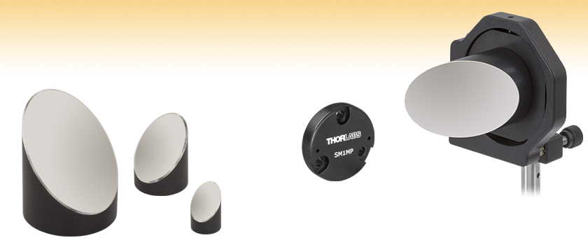
SM1MPThe SM1MP OAP Mirror Adapter is externally SM1 threaded (1.035"-40) which allows a Ø1" OAP mirror to be directly mounted to an internally SM1-threaded component. The adapter is designed to allow easy adaptability to a 30 mm cage system as well as SM1-threaded mirror, translation, and rotation mounts. The included SM1RR retaining ring secures the adapter in place when it is threaded into a mount. An SPW606 and a SPW909 or SPW801 Spanner Wrench can be used to thread the retaining ring and adapter, respectively. Three 4-40 cap screws and the required 0.05" hex key are provided with each adapter.
The shaded region in the graph denotes the range over which we guarantee the specified reflectance. Please note that the reflectance outside of this band is typical and can vary from lot to lot, especially in out-of-band regions where the reflectance is fluctuating or sloped.
Light absorption processes e.g. in solid materials generally arise from the interaction of the electromagnetic wave with electrons, exciting those to excited energy levels. Thereafter, it takes some time (the electron–lattice thermalization time) for that energy to be transferred to the atomic nuclei, i.e., to vibration energy. That typically happens within a couple of picoseconds, and thereafter it takes far longer times to distribute that heat over some volume of the medium. That means that the thermalization, let alone the heat conduction, can take far more time than the pulse duration of a femtosecond laser. That has important implications for laser material processing with ultrafast lasers, where the involved processes cannot be understood as simply heating up the material. Instead, one is dealing with highly non-equilibrium states of matter, which can lead to rapid application of material while very nearby other material, not directly hit by the laser radiation, is not even significantly heated.
Choosing the right mounting adapter is the first step in aligning an OAP mirror. Guidance on how to select the right mounting adapter is located below. For information on how to align an OAP mirror, watch our video to the right.
Thorlabs' LIDT testing is done in compliance with ISO/DIS 11254 and ISO 21254 specifications.First, a low-power/energy beam is directed to the optic under test. The optic is exposed in 10 locations to this laser beam for 30 seconds (CW) or for a number of pulses (pulse repetition frequency specified). After exposure, the optic is examined by a microscope (~100X magnification) for any visible damage. The number of locations that are damaged at a particular power/energy level is recorded. Next, the power/energy is either increased or decreased and the optic is exposed at 10 new locations. This process is repeated until damage is observed. The damage threshold is then assigned to be the highest power/energy that the optic can withstand without causing damage. A histogram such as that below represents the testing of one BB1-E02 mirror.
MP508P1The unthreaded MP508P1 OAP Mirror Adapter is sized to fit inside a Ø3" mirror mount, such as the KS3 Mirror Mount shown above. Three standard 8-32 cap screws and the required 9/64" hex key are provided with each adapter.
Through different kinds of processes, which are explained in the following, light can be absorbed in various media. This implies that the optical energy is converted into some other form of energy (but sometimes back again to optical energy). In most cases, the energy is eventually transformed into heat (thermal energy).
Our Kinematic Right-Angle Mount and Mounting Adapters for Ø1" Off-Axis Parabolic Mirrors provide mounting alternatives to our smooth bore kinematic mirror mounts. Each offers three #4 counterbores that are positioned to align with the 4-40 tapped holes on our Ø1" OAP mirrors.
The pulse length must now be compensated for. The longer the pulse duration, the more energy the optic can handle. For pulse widths between 1 - 100 ns, an approximation is as follows:
The rear-loading, removable mounting plate features our ball and V-groove design that allows it to be precisely kinematically positioned on the body of the mount. The rear-loading design ensures that the optic remains accessible even after the mount is fitted with cage rods or lens tubes.
As light carries energy, the absorption of light is associated with the deposition of energy in the absorbing medium. In most cases, that energy is mostly converted into heat, although sometimes a substantial amount of the received energy is radiated away as fluorescence.
Off-axis Ellipsoidal mirror
KCB1P(/M)The KCB1P(/M) Right-Angle Kinematic Mount provides ±4° of pitch and yaw adjustment for a Ø1" off-axis parabolic (OAP) mirror mounted on a plate that positions the surface of the mirror at a 45° angle. The ports are SM1 threaded (1.035"-40) for compatibility with our SM1 Lens Tubes and each face has four Ø6 mm smooth bore holes for compatibility with the ER rods for our 30 mm Cage System. The top and bottom of the mount also offer 1/4"-20 (M6) mounting holes for compatibility with Ø1/2" and Ø1" Posts.
Our Mounting Adapters for Ø1/2" Off-Axis Parabolic Mirrors provide mounting alternatives to our smooth bore kinematic mirror mounts. Each contains three #4 counterbores that are positioned to align with the 4-40 tapped holes on our Ø1/2" OAP mirrors. Three 4-40 cap screws and the required 3/32" hex key are provided with each adapter.
Due the asymmetry of the reflector, when an OAP mirror rotates, the position of its focal point also rotates. Since this could negatively impact the performance of an optical system, the mirror should be fixed so that the reflective surface cannot rotate around its optical axis.
The OAP mirrors sold here are fabricated using aluminum substrates. The bottom of each mirror has three tapped mounting holes in a triangle pattern and an alignment hole for use with a mounting adapter (see the OAP Mounting tab for more details). The non-optical surfaces are black-anodized and laser-engraved with the item number for easy identification as shown in the image above.
For Ø3" OAP mirrors, we offer the SM2MP3 mounting adapter, which contains four 8-32 tapped holes for post mounting and has external SM2 threading for mounting in our SM2-threaded components, such as the K6X2 6-axis kinematic mount.
There are also many cases where a material contains some absorbing dopant while the host material itself exhibits only negligible absorption. This is the case for solid-state (doped-insulator) gain media.
MP508P2(/M)The MP508P2(/M) OAP Mirror Adapter contains four 8-32 (M4) taps, for post mounting, that orient the OAP mirror at right angles. The distance from the center of the optic to the edge of the mount in the MP508P2 is 1.5" (38.1 mm), allowing for standardized optical axis heights when used with a fixed height post, such as our Ø1" Posts. Please note that the MP508P2(/M) is not compatible with Ø3" mirror mounts, and is instead designed for post mounting. Three standard 8-32 cap screws and the required 9/64" hex key are provided with each adapter.
An OAP mirror can also be used to collimate a spherical wave, if its origin coincides with the focal point of the mirror.
The focal axis of the OAP mirror passes through the focal point and the center of the OAP mirror. The focal and optical axes of an OAP mirror are not parallel. In contrast, these axes coincide for parabolic mirrors whose reflective surfaces are centered on optical axis of the parent parabola.
Please do not enter personal data here. (See also our privacy declaration.) If you wish to receive personal feedback or consultancy from the author, please contact him, e.g. via e-mail.
The following is a general overview of how laser induced damage thresholds are measured and how the values may be utilized in determining the appropriateness of an optic for a given application. When choosing optics, it is important to understand the Laser Induced Damage Threshold (LIDT) of the optics being used. The LIDT for an optic greatly depends on the type of laser you are using. Continuous wave (CW) lasers typically cause damage from thermal effects (absorption either in the coating or in the substrate). Pulsed lasers, on the other hand, often strip electrons from the lattice structure of an optic before causing thermal damage. Note that the guideline presented here assumes room temperature operation and optics in new condition (i.e., within scratch-dig spec, surface free of contamination, etc.). Because dust or other particles on the surface of an optic can cause damage at lower thresholds, we recommend keeping surfaces clean and free of debris. For more information on cleaning optics, please see our Optics Cleaning tutorial.
The graph to the right visualizes the equations above, showing the relationship between the point source's divergence and collimated beam diameter. Each line represents an OAP with a particular reflected focal length. Not listed here is the diameter of the OAP. The clear aperture of the OAP you select should be larger than the desired beam output diameter.
Further, the modified population in electronic states can substantially modify the absorption at the wavelength of the absorbed light and also at other wavelengths. It has already been mentioned above that absorption may be saturated. In other cases, light absorption is strongly increased by the light-induced changes of the state of matter. That is often exploited in laser material processing, where the initial absorption e.g. by a metal is weak, but strongly increases once the material is strongly excited (anomalous absorption). In various materials, one may obtain excited-state absorption at wavelengths where the material would normally not be absorbing. In semiconductors, at high intensities one obtains free carrier absorption.
Use this formula to calculate the Adjusted LIDT for an optic based on your pulse length. If your maximum energy density is less than this adjusted LIDT maximum energy density, then the optic should be suitable for your application. Keep in mind that this calculation is only used for pulses between 10-9 s and 10-7 s. For pulses between 10-7 s and 10-4 s, the CW LIDT must also be checked before deeming the optic appropriate for your application.
The energy density of your beam should be calculated in terms of J/cm2. The graph to the right shows why expressing the LIDT as an energy density provides the best metric for short pulse sources. In this regime, the LIDT given as an energy density can be applied to any beam diameter; one does not need to compute an adjusted LIDT to adjust for changes in spot size. This calculation assumes a uniform beam intensity profile. You must now adjust this energy density to account for hotspots or other nonuniform intensity profiles and roughly calculate a maximum energy density. For reference a Gaussian beam typically has a maximum energy density that is twice that of the 1/e2 beam.
Thorlabs' Off-Axis Parabolic (OAP) Mirrors are mirrors whose reflective surfaces are segments of a parent paraboloid. They achromatically focus a collimated beam or collimate a divergent source, and their off-axis design separates the focal point from the rest of the beam path. The reflective design eliminates phase delays and absorption losses introduced by transmissive optics and makes these well suited for use with femtosecond pulsed lasers.
Pulsed Microsecond Laser ExampleConsider a laser system that produces 1 µs pulses, each containing 150 µJ of energy at a repetition rate of 50 kHz, resulting in a relatively high duty cycle of 5%. This system falls somewhere between the regimes of CW and pulsed laser induced damage, and could potentially damage an optic by mechanisms associated with either regime. As a result, both CW and pulsed LIDT values must be compared to the properties of the laser system to ensure safe operation.
We are generally able to produce custom OAP mirrors and aspheric mirrors with short lead times. For modifications to an existing part, delivery in 4-6 weeks is standard. For custom shapes and long focal length optics, a 6-8 week lead time is typical. To receive more information or a quote for a custom optic, please contact Tech Support.
We offer three types of mounting plates for Ø1/2", Ø1", and Ø2" OAP mirrors. The first type is designed to be mounted in any Ø1", Ø2", or Ø3" mirror mount, depending upon the diameter of the OAP mirror. The second type, designed for post mounting, contains an 8-32 (M4) tapped hole on all four sides for direct mechanical compatibility with Ø1/2" Posts. The third type is externally SM threaded for direct compatibility with any of our internally SM-threaded components, such as our rotation mounts. For Ø1" 90° OAP mirrors, the KCB1P(/M) right-angle mount allows for cage system integration. The table below shows all of these options.
Off axis parabolic mirrorsfor sale
Off-AxisParabolicMirror Thorlabs
In some special cases, nearly all of the absorbed light causes fluorescence rather than heat, and there can be even a net cooling effect (→ laser cooling). It may even happen that at some (typically longer) wavelengths one obtains laser amplification for strong enough excitation of the medium, usually involving a population inversion. The medium may then generate laser radiation which may remove a substantial fraction of the deposited energy.
If this relatively long-pulse laser emits a Gaussian 12.7 mm diameter beam (1/e2) at 980 nm, then the resulting output has a linear power density of 5.9 W/cm and an energy density of 1.2 x 10⁻⁴ J/cm2 per pulse. This can be compared to the LIDT values for a WPQ10E-980 polymer zero-order quarter-wave plate, which are 5 W/cm for CW radiation at 810 nm and 5 J/cm2 for a 10 ns pulse at 810 nm. As before, the CW LIDT of the optic scales linearly with the laser wavelength, resulting in an adjusted CW value of 6 W/cm at 980 nm. On the other hand, the pulsed LIDT scales with the square root of the laser wavelength and the square root of the pulse duration, resulting in an adjusted value of 55 J/cm2 for a 1 µs pulse at 980 nm. The pulsed LIDT of the optic is significantly greater than the energy density of the laser pulse, so individual pulses will not damage the wave plate. However, the large average linear power density of the laser system may cause thermal damage to the optic, much like a high-power CW beam.
Off-axisparabolicmirror alignment
When pulse lengths are between 1 ns and 1 µs, laser-induced damage can occur either because of absorption or a dielectric breakdown (therefore, a user must check both CW and pulsed LIDT). Absorption is either due to an intrinsic property of the optic or due to surface irregularities; thus LIDT values are only valid for optics meeting or exceeding the surface quality specifications given by a manufacturer. While many optics can handle high power CW lasers, cemented (e.g., achromatic doublets) or highly absorptive (e.g., ND filters) optics tend to have lower CW damage thresholds. These lower thresholds are due to absorption or scattering in the cement or metal coating.
As previously stated, pulsed lasers typically induce a different type of damage to the optic than CW lasers. Pulsed lasers often do not heat the optic enough to damage it; instead, pulsed lasers produce strong electric fields capable of inducing dielectric breakdown in the material. Unfortunately, it can be very difficult to compare the LIDT specification of an optic to your laser. There are multiple regimes in which a pulsed laser can damage an optic and this is based on the laser's pulse length. The highlighted columns in the table below outline the relevant pulse lengths for our specified LIDT values.
A general distinction is between intrinsic and extrinsic absorption. Extrinsic absorption (also sometimes called parasitic absorption) results from things which could in principle be avoided – for example, from impurities and structural defects which could be absent in pure high quality material. Intrinsic absorption results from basic properties of the pure material.
Note: this box searches only for keywords in the titles of articles, and for acronyms. For full-text searches on the whole website, use our search page.
According to the test, the damage threshold of the mirror was 2.00 J/cm2 (532 nm, 10 ns pulse, 10 Hz, Ø0.803 mm). Please keep in mind that these tests are performed on clean optics, as dirt and contamination can significantly lower the damage threshold of a component. While the test results are only representative of one coating run, Thorlabs specifies damage threshold values that account for coating variances.
Provide Access to the Beam in a Fiber NetworkA pair of OAP mirrors can be used to create a free-space leg in an optical fiber system, which is one way to provide access to the light beam. The illustration in Figure 5 shows an example of this configuration, which can be useful when filters or other bulk optics need to be inserted into the beam path. The length of the free-space leg can be adjusted without disturbing alignment.
The energy density of the beam can be compared to the LIDT values of 1 J/cm2 and 3.5 J/cm2 for a BB1-E01 broadband dielectric mirror and an NB1-K08 Nd:YAG laser line mirror, respectively. Both of these LIDT values, while measured at 355 nm, were determined with a 10 ns pulsed laser at 10 Hz. Therefore, an adjustment must be applied for the shorter pulse duration of the system under consideration. As described on the previous tab, LIDT values in the nanosecond pulse regime scale with the square root of the laser pulse duration:
More specific terms: infrared absorption, excited-state absorption, pump absorption, light-induced absorption, multiphonon absorption, multiphoton absorption, two-photon absorption, pump absorption
As described above, the maximum energy density of a Gaussian beam is about twice the average energy density. So, the maximum energy density of this beam is ~0.7 J/cm2.
LIDT in linear power density vs. pulse length and spot size. For long pulses to CW, linear power density becomes a constant with spot size. This graph was obtained from [1].
When using an off-axis parabolic mirror to collimate a point source, selection of the appropriate mirror is often done based on the desired output beam diameter. Beam diameter can be calculated using the divergence half-angle of the incident light (Θ) and the reflected focal length of the OAP. To calculate the beam diameter in the small angle approximation, use the following equation:
Collimate Light from a Point SourceTo obtain highly collimated light from a point source, the point source should be located at the mirror's focal point.
SM2MPThe SM2MP OAP Mirror Adapter is externally SM2 threaded (2.035"-40), which allows a Ø2" OAP mirror to be directly mounted to an internally SM2-threaded component. The adapter is designed to allow easy adaptability to a 60 mm cage system as well as SM2-threaded mirror, translation, and rotation mounts. The included SM2RR retaining ring secures the adapter in place when it is threaded into a mount. An SPW604 and SPW801 Spanner Wrench can be used to thread the retaining ring and adapter, respectively. Three low profile 8-32 cap screws and the required 5/64" hex key are provided with each adapter.
OAP mirrors are not rotationally symmetric. This is due to their reflective surfaces being taken from sections of the parent parabola curve located away from the focal point (Figure 6).
Pulsed Nanosecond Laser Example: Scaling for Different Pulse DurationsSuppose that a pulsed Nd:YAG laser system is frequency tripled to produce a 10 Hz output, consisting of 2 ns output pulses at 355 nm, each with 1 J of energy, in a Gaussian beam with a 1.9 cm beam diameter (1/e2). The average energy density of each pulse is found by dividing the pulse energy by the beam area:
The angle between the focused beam and the collimated beam (off-axis angle) is 90°. As shown to the left, the propagation axis of the collimated beam should be normal to the bottom of the substrate to achieve a proper focus. The diamond-turned parabolic surface has a protected silver coating that provides >97% average reflectance from 450 nm - 2 µm and >95% average reflectance from 2 µm to 20 µm. Though the overcoat helps to protect silver from tarnishing, high humidity environments should be avoided.
Thorlabs expresses LIDT for CW lasers as a linear power density measured in W/cm. In this regime, the LIDT given as a linear power density can be applied to any beam diameter; one does not need to compute an adjusted LIDT to adjust for changes in spot size, as demonstrated by the graph to the right. Average linear power density can be calculated using the equation below.
When setting up this system, the fibers' end faces must be aligned so that their cores coincide with the source and target focal points, respectively. The collimated beam paths of both mirrors should be co-linear and completely overlapping.
The optical performance of the mirror is also sensitive to alignment drift with respect to the other five degrees of freedom. One way to protect against alignment drift is to use a fixed, rather than a kinematic, mount.
Absorption of light can also have electrical effects. For example, there are photoresistors, where the electrical resistance is reduced by absorbed light. In photodiodes and phototransistors, one exploits the internal photoelectric effect, related to the excitation of electric carriers by light absorption.
CW Laser ExampleSuppose that a CW laser system at 1319 nm produces a 0.5 W Gaussian beam that has a 1/e2 diameter of 10 mm. A naive calculation of the average linear power density of this beam would yield a value of 0.5 W/cm, given by the total power divided by the beam diameter:
Relay an ImageA single OAP mirror is not recommended for finite conjugate imaging applications, when neither light beam is collimated, but a pair of OAP mirrors can successfully be used for this purpose. An example setup is illustrated in Figure 4.
If the incident light is in a coherent state, exhibiting the standard shot noise level, the extra noise added through linear absorption is just enough to keep the residual light at the shot noise level (which is relatively stronger for weaker light).
This adjustment factor results in LIDT values of 0.45 J/cm2 for the BB1-E01 broadband mirror and 1.6 J/cm2 for the Nd:YAG laser line mirror, which are to be compared with the 0.7 J/cm2 maximum energy density of the beam. While the broadband mirror would likely be damaged by the laser, the more specialized laser line mirror is appropriate for use with this system.
Even simple linear absorption processes introduce some amount of quantum noise. This can be intuitively understood by considering that some of the incident photon are randomly removed, while other photons remain in the light beam. An initially perfectly regular stream of photons (→ amplitude-squeezed light) would thus be converted into a random stream of photons, exhibiting some intensity noise.
Beam diameter is also important to know when comparing damage thresholds. While the LIDT, when expressed in units of J/cm², scales independently of spot size; large beam sizes are more likely to illuminate a larger number of defects which can lead to greater variances in the LIDT [4]. For data presented here, a <1 mm beam size was used to measure the LIDT. For beams sizes greater than 5 mm, the LIDT (J/cm2) will not scale independently of beam diameter due to the larger size beam exposing more defects.
SM05MPThe SM05MP OAP Mirror Adapter is externally SM05 threaded (0.535"-40), which allows a Ø1/2" OAP mirror to be directly mounted to an internally SM05-threaded component. The adapter is designed to allow easy adaptability to a 16 mm cage system as well as SM05-threaded mirror, translation, and rotation mounts. The included SM05RR retaining ring secures the adapter in place when it is threaded into a mount. An SPW603 Spanner Wrench can be used to tighten the retaining ring against the OAP mirror housing.
Pulses shorter than 10-9 s cannot be compared to our specified LIDT values with much reliability. In this ultra-short-pulse regime various mechanics, such as multiphoton-avalanche ionization, take over as the predominate damage mechanism [2]. In contrast, pulses between 10-7 s and 10-4 s may cause damage to an optic either because of dielectric breakdown or thermal effects. This means that both CW and pulsed damage thresholds must be compared to the laser beam to determine whether the optic is suitable for your application.
Alternatively, all of our OAP mirrors may be directly mounted in our Precision Kinematic Mirror Mounts using their outer diameter.
Care and HandlingSilver coated mirrors require additional care due to their susceptibility to damage from environmental conditions and improper handling. Fingerprints, contact with abrasive surfaces, and environments with high humidity or temperature will diminish the effectiveness of the protective overcoat leaving the silver coating susceptible to oxidation and degradation. When working with silver mirrors, follow standard practices for handling optics. Latex gloves or similar protective coverings are recommended to prevent oil and other residues on the user’s fingers from reaching the optical surface. Even with such precautions, care should be taken not to touch the mirrored face or edges. Silver mirrors should be used and stored in areas at room temperature with minimal humidity. For information on how to clean mirrors and other optics, visit our Optic Cleaning Tutorial.
The bottom of each off-axis parabolic (OAP) mirror contains three tapped mounting holes in a triangle pattern and an alignment hole. These holes are used to attach our Mounting Adapters, which contain three corresponding counterbore holes or captive screws and an alignment pin (see the image to the right). Together, these features allow our OAP mirrors to be securely mounted. The tapped holes are also useful in OEM applications.
In nonlinear absorption, does the laser pulse duration also affect the absorption coefficient alongside with the intensity?
Off-axisparabolicmirror Zemax
LIDT in energy density vs. pulse length and spot size. For short pulses, energy density becomes a constant with spot size. This graph was obtained from [1].
Thorlabs recommends against directing collimated light along the focal axis of OAP mirrors, or along any direction that is not parallel to the optical axis, since the light will not focus to a diffraction-limited spot.
Pulsed Nanosecond Laser Example: Scaling for Different WavelengthsSuppose that a pulsed laser system emits 10 ns pulses at 2.5 Hz, each with 100 mJ of energy at 1064 nm in a 16 mm diameter beam (1/e2) that must be attenuated with a neutral density filter. For a Gaussian output, these specifications result in a maximum energy density of 0.1 J/cm2. The damage threshold of an NDUV10A Ø25 mm, OD 1.0, reflective neutral density filter is 0.05 J/cm2 for 10 ns pulses at 355 nm, while the damage threshold of the similar NE10A absorptive filter is 10 J/cm2 for 10 ns pulses at 532 nm. As described on the previous tab, the LIDT value of an optic scales with the square root of the wavelength in the nanosecond pulse regime:
Off-AxisParabolic mirrorswith Alignment Through Holes
While this rule of thumb provides a general trend, it is not a quantitative analysis of LIDT vs wavelength. In CW applications, for instance, damage scales more strongly with absorption in the coating and substrate, which does not necessarily scale well with wavelength. While the above procedure provides a good rule of thumb for LIDT values, please contact Tech Support if your wavelength is different from the specified LIDT wavelength. If your power density is less than the adjusted LIDT of the optic, then the optic should work for your application.
Now compare the maximum energy density to that which is specified as the LIDT for the optic. If the optic was tested at a wavelength other than your operating wavelength, the damage threshold must be scaled appropriately [3]. A good rule of thumb is that the damage threshold has an inverse square root relationship with wavelength such that as you move to shorter wavelengths, the damage threshold decreases (i.e., a LIDT of 1 J/cm2 at 1064 nm scales to 0.7 J/cm2 at 532 nm):
Non-transparent objects can be attributed an absorptance, which is the fraction of incident light which is absorbed rather than transmitted, reflected or scattered.
Parabolic vs. Off-Axis Parabolic MirrorsThe reflective surface of an OAP mirror is a section of the parent parabola that is not centered on the parent's optical axis (Figure 1). A conventional parabolic mirror is illustrated in Figure 2.
Focus Collimated LightIf a parabolic or OAP mirror is being used to focus a beam of collimated light to a diffraction-limited point, the light must be directed along the mirror's optical axis (Figures 1 and 2).
MP127P2(/M)The MP127P2(/M) OAP Mirror Adapter contains four 8-32 (M4) taps for post mounting that orient the OAP mirror at right angles. The distance from the center of the optic to the edge of the mount in the MP127P2 is 1/2" (12.5 mm), allowing for standardized optical axis heights when used with a fixed height post, such as our Ø1" Posts. Please note that the MP127P2(/M) is not compatible with Ø1" mirror mounts, and is instead designed for post mounting.
Note: the article keyword search field and some other of the site's functionality would require Javascript, which however is turned off in your browser.
Our Ø1/2", Ø1", and Ø2" OAP mirrors can also be adapted to our SM threads by placing them into our SM Thread to Double Bore Adapters. This type of adapter allows rotation of the OAP mirror with respect to the adapter prior to securing its position, whereas when using the SM-threaded adapters offered on this page, the final location of the OAP mirror is dictated either by the threads themselves (when fully threaded into a mount) or by using the provided retaining ring to secure it in place.
Here you can submit questions and comments. As far as they get accepted by the author, they will appear above this paragraph together with the author’s answer. The author will decide on acceptance based on certain criteria. Essentially, the issue must be of sufficiently broad interest.
If light is absorbed by atoms or molecules of a gas, light forces associated with the absorption may become relevant. They can be used for Doppler cooling, for example.
Impurities can also modify intrinsic absorption features – for example, shift the band gap energy and the corresponding absorption edge when a semiconductor compound is formed.
Linear absorption means that the absorption coefficient is independent of the optical intensity. There are also nonlinear absorption processes, where the absorption coefficient is a linear or higher-order function of the intensity. For example, two-photon absorption is a process where two photons are absorbed simultaneously, and the absorption coefficient rises linearly with the intensity. Multiphoton absorption processes of higher order are often involved in laser-induced damage caused by intense laser pulses.
Light from a point source will be poorly collimated if the point source is placed along the OAP mirror's optical axis, or anywhere else that is not the focal point.
The optical axis of an OAP mirror is parallel to, but displaced from the optical axis of the parent parabola. The focal point of the OAP mirror coincides with that of the parent parabola.
Parabolic and off-axis parabolic (OAP) mirrors will only provide the expected well-collimated beam or diffraction-limited focal spot when the correct beam type is incident along the proper axis. This due to the parabolic shape of these mirrors' reflective surfaces, which are not symmetric around their focal points.
MP254P2(/M)The MP254P2(/M) OAP Mirror Adapter contains four 8-32 (M4) taps for post mounting that orient the OAP mirror at right angles. The distance from the center of the optic to the edge of the mount in the MP254P2 is 1" (25.4 mm), allowing for standardized optical axis heights when used with a fixed height post, such as our Ø1" Posts. Please note that the MP254P2(/M) is not compatible with Ø2" mirror mounts, and is instead designed for post mounting. Three 4-40 cap screws and the required 3/32" hex key are provided with each adapter.
Our SPDT competency also enables us to produce mirrors with other custom biconic surfaces and aspheric shapes, including on-axis parabolic, conical, and toroidal mirrors. These custom mirror shapes can be used in a wide variety of optical instruments and specialized imaging systems. For example, toroidal mirrors, which are used to image off-axis points without introducing astigmatism, are commonly used in compact Czerny-Turner monochromators. Conical mirrors, on the other hand, are ideal for non-imaging applications that require 360° of uniform illumination.
If absorption is caused by some absorbing dopant, the contribution to the absorption per dopant atom or ion is often quantified with an absorption cross-section.
Using a shear plate interferometer can be helpful when aligning an OAP mirror to an input point source. The shear plate interferometer should intercept the output beam (Figure 7), to assess its collimation quality. Alignment is optimized when the quality of the collimated beam is optimized.
As absorption coefficients are wavelength-dependent, one often produces absorption spectra, showing an absorption coefficient as a function of wavelength or optical frequency.
However, the maximum power density of a Gaussian beam is about twice the maximum power density of a uniform beam, as shown in the graph to the right. Therefore, a more accurate determination of the maximum linear power density of the system is 1 W/cm.
MP127P1The unthreaded MP127P1 OAP Mirror Adapter is sized to fit inside a Ø1" mirror mount, such as the KS1 Mirror Mount shown above.
An AC127-030-C achromatic doublet lens has a specified CW LIDT of 350 W/cm, as tested at 1550 nm. CW damage threshold values typically scale directly with the wavelength of the laser source, so this yields an adjusted LIDT value:


 Ms.Cici
 8618319014500