
Optical Aberrations | Olympus LS - aberrations
Emerging as a de facto standard over the last decade, OptiGrating has delivered powerful and user friendly design software for modeling integrated and fiber optic devices that incorporate optical gratings.
All fiber mach zehnder interferometers for sensing applications
OptiFDTD is a powerful, highly integrated, and user friendly CAD environment that enables the design and simulation of advanced passive and non-linear photonic components.
Note: You can also first generate a template script by selecting Simulation > Generate Scanning Script and then edit it as shown above.
There is nothing comparable to a shutter of the camera in the eye. The eyelid is like a lens hood. When the eyelid is open the image is continuously projected on to the retina unlike in a movie camera. However if the question is on frames per second (number of static images) required to produce a sense of seamless motion this article might be of some help. In video camera instead of a shutter speed it is the number of times the image on the sensor is sampled(recorded) per second electronically. The eye is more similar to a video camera. The retina has rods and cones which has variable 'refresher' rates which makes it more complicated to calculate exact figures.
The optimal design of a given optical communication system depends directly on the choice of fiber parameters. OptiFiber uses numerical mode solvers and other models specialized to fibers for calculating dispersion, losses, birefringence, and PMD.
Optiwave software can be used in different industries and applications, including Fiber Optic Communication, Sensing, Pharma/Bio, Military & Satcom, Test & Measurement, Fundamental Research, Solar Panels, Components / Devices, etc..
OptiInstrument addresses the needs of researchers, scientists, photonic engineers, professors and students who are working with instruments.
OptiInstrument addresses the needs of researchers, scientists, photonic engineers, professors and students who are working with instruments.
The human eye and its brain interface, the human visual system, can process 10 to 12 separate images per second, perceiving them individually.
We have specified an electrode region with three electrodes, all with zero voltage, positioned slightly off the symmetry axis of the Mach-Zehnder interferometer.
We assume that the integrated switch is created on a z-cut wafer of Lithium Niobate and is surrounded by air cladding. The device is oriented along the Y-optical axis of the Lithium Niobate. Therefore, we need to define a diffused material for the substrate and a dielectric material for cladding.
mach-zehnder modulator
OptiSystem is a comprehensive software design suite that enables users to plan, test, and simulate optical links in the transmission layer of modern optical networks.
OptiFDTD is a powerful, highly integrated, and user friendly CAD environment that enables the design and simulation of advanced passive and non-linear photonic components.
Decoherence
OptiBPM is a comprehensive CAD environment used for the design of complex optical waveguides. Perform guiding, coupling, switching, splitting, multiplexing, and demultiplexing of optical signals in photonic devices.
Optiwave software can be used in different industries and applications, including Fiber Optic Communication, Sensing, Pharma/Bio, Military & Satcom, Test & Measurement, Fundamental Research, Solar Panels, Components / Devices, etc..
OptiSystem is a comprehensive software design suite that enables users to plan, test, and simulate optical links in the transmission layer of modern optical networks.
The optimal design of a given optical communication system depends directly on the choice of fiber parameters. OptiFiber uses numerical mode solvers and other models specialized to fibers for calculating dispersion, losses, birefringence, and PMD.
MZI COMSOL
In the Electrode Region dialog box, you can edit the start and end position of the region (Z Position tab), change the reference refractive index and propagation step in the region (Calculation tab), change material properties of the cladding, substrate, and substrate layers (Substrate tab). The Electrode tab allows you to define the electrodes on the substrate. The electrode region in this lesson starts at 11500μm and ends at 21500μm.
Emerging as a de facto standard over the last decade, OptiGrating has delivered powerful and user friendly design software for modeling integrated and fiber optic devices that incorporate optical gratings.
To build the top waveguides by using the mirror options, perform the following procedure steps for each waveguide in the layout.
To change the voltage of the central electrode, in the Electrode Region dialog box, Electrode tab, select the electrode set in the Electrode sets table, and click Edit. Type 6.75 in Electrode 2—Voltage (V).
This is more like a volume knob than a shutter speed since the same signal comes out at the same rate of each light sensor, but it has a similar effect — it modulates the intensity of the image.
Modal analysis is a pivotal component of modelling optical structures. OptiMode serves as a robust CAD platform for the design and modal analysis of waveguide structures.
马赫曾德尔调制器
In this example, we want to build electrodes on the top of a buffer layer. The properties of the buffer layer can be defined under the Electrode tab (see Figure 9). As we did not define a buffer material when we began the lesson, we have to do so now.
An electro-optic switch is a device used in integrated fibre optics. The device is based on Mach-Zehnder interferometer made by Titanium diffusion in Lithium Niobate substrate. The switching between the ports is achieved by an electro-optic effect within such structure. Voltage, applied to the electrodes deposited on the integrated Mach-Zehnder interferometer, creates an electric field distribution within the substrate, which consequently changes its refractive index. If properly designed, the induced change in the refractive index leads to different coupling between individual ports.
Run the simulation for zero voltage at the central electrode and for 6.75V at the central electrode. You should observe full switching at 6.75V.
When we run the simple scanning script, we obtain a graph of the optical field overlap versus the number of iterations. It then becomes clear that the electro-optic switch is fully switching the input signal from one output port to another for the second electrode voltage between 6.4 and 7.2V.
Electrode 1 Width 50 Voltage 0.0 Electrode 2 Width 26 Voltage 0.0 Electrode 3 Width 50 Voltage 0.0 Gap 1-2 6.0 Gap 2-3 6.0 Electrode 2
MZI
Actually I feel dumb but there is a simple answer to this question. You can get lost in the above physiology. The simpler answer is about 20 fps. Whenever strobing stops and persistence of vision takes over to create a continuous image is an interesting way to answer this question. That's how television and movies (and videos) work. 30 fps looks pretty smooth. It's not a perfect answer because 60 or 100 fps are functionally useful for situations like video games where fast reaction time is important.
OptiSPICE is the first circuit design software for analysis of integrated circuits including interactions of optical and electronic components. It allows for the design and simulation of opto-electronic circuits at the transistor level, from laser drivers to transimpedance amplifiers, optical interconnects and electronic equalizers.
Beam splitter
OptiSPICE is the first circuit design software for analysis of integrated circuits including interactions of optical and electronic components. It allows for the design and simulation of opto-electronic circuits at the transistor level, from laser drivers to transimpedance amplifiers, optical interconnects and electronic equalizers.
Sagnac effect
Tip: to view the whole substrate, it can be useful to change the setting of the Display ratio (Z/X). To do this, select Preferences > Layout Options > Display ratio, and type 200.
You can perform more detailed investigations of the electro-optic switch using scripting language. For example, we can scan the voltage on the central electrode and observe the overlap integral of the output ports with the waveguide mode.
Modal analysis is a pivotal component of modelling optical structures. OptiMode serves as a robust CAD platform for the design and modal analysis of waveguide structures.
Stack Exchange network consists of 183 Q&A communities including Stack Overflow, the largest, most trusted online community for developers to learn, share their knowledge, and build their careers.
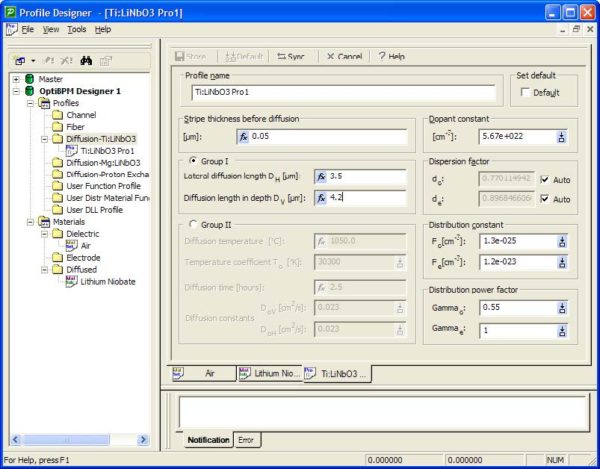
The waveguides of Mach-Zehnder interferometer are created by diffusion of Titanium in Lithium Niobate substrate. We will need only one Ti-diffused profile :
Thickness μm 0.3 Horizontal permittivity 4 Vertical permittivity 4 Material buffer Electrode thickness μm 4
The light receptor of the eye is a protein called Rhodopsin. To me the equivalent of shutter speed for the eye is the (de)sensitization of rhodopsin by phosphorylation. The brighter the light, the more sites on rhodopsin are phosphorylated, diminishing the intensity of the signal coming from the photo receptor via the transducin G protein that conveys the visual signal onward.
Not all of your rods/cones fire at any given moment. Exception is when a bright flash of light is viewed. Recovery time from the resulting flash blindness is pretty slow -- seconds. But there's some photobleaching there, so maybe that's not fair.
OptiBPM is a comprehensive CAD environment used for the design of complex optical waveguides. Perform guiding, coupling, switching, splitting, multiplexing, and demultiplexing of optical signals in photonic devices.


 Ms.Cici
 8618319014500