
OPTATEC, Frankfurt, Germany | DAC International - optatec frankfurt
The #8 is the diameter, with 32 threads per inch. And I could make you a #8–32 that is 8 inches long if you want. Metric stuff is quite similar ...
Laser lens focusprice
Jan 14, 2020 — Interview with Dr. Lee Burnett and Laura Turner of Student Doctor Network [Show Summary]. Applying to medical school is a stressful process, and ...
A good antireflection coating will increase the transmittance of the focusing lens, greatly improve the cutting performance and extend the spanlife.
If the lens has two coated surfaces, such as a lens, each surface needs to be cleaned in this way. The first side needs to be placed on a layer of clean lens paper for protection.
According to our long-term use experience, the Meniscus lenses performs better than the plano-convex focusing lens, which is also one of the most popular reasons in the market.
The system optical performance analysis indicates that upon an accurate focalization the source is able to achieve a narrow emitted beam by means of small size optics. Figure 6 demonstrate a 2° average divergence is achievable with 1 inch optics, with average color uniformity over the projected image, since some yellow ghosting is visible on the minor axis of the beam.
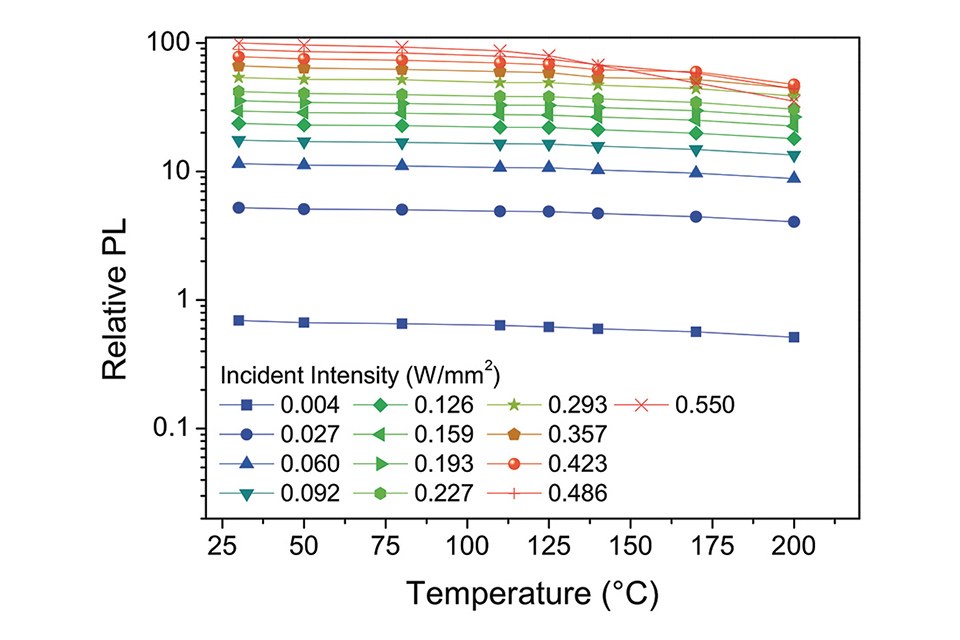
The laser radiation then hits the phosphor with a much higher irradiance, thus allowing much higher luminance, but also locally increasing the temperature of the phosphor due to Stokes shift losses, resulting in less than unity efficiency. The structure of a laser lighting system is dependent on whether the radiation passes through the phosphor deposited on a transparent substrate (similar to LED mixing chamber solution) or is reflected from the phosphor itself deposited into a mirrored substrate.
The cotton ball must be dipped in acetone and the lens must be cleaned under light and moved in a circular motion. Once the cotton swab is dirty, it must be replaced. The cleaning should be done at one time to avoid the formation of ridges.
In conclusion, the research shows that laser-based lighting, although still a growing technology, can push the limits of solid-state lighting in terms of efficiency at high currents thanks to low droop and optical management of the emitted light. The technological limits are still related to the laser diode performance and costs and the development of efficient cooling structures for the phosphor template.
First, use an air ball to blow off the floats on the surface of the lens, especially the lens with tiny particles and floccules on the surface. This step is necessary. But never use air compressor, because the air will contain oil and water droplets, which will deepen the pollution of the lens.
Laser lenstypes
Oct 17, 2024 — Monochromator, instrument that supplies light of one colour or light within a narrow range of wavelengths. Unwanted wavelengths (colours) ...
Will LEDs or lasers win in the long run? It is very likely that both technologies will find wide application and create a real change in the lighting paradigm. The real winners will be the end users who will have access to two flexible and different technologies for lighting: LEDs and lasers. This will increase the degrees of freedom for designers, leading to an even bigger penetration of solid-state lighting in the application market.
5. The user should avoid talking above the lens and keep food, beverages and other potential pollutants away from the work environment.
The lens you need is directly related to your application. These are some important considerations that will define the lens you must use:
References:[1] H. König, A. Lell, B. Stojetz, M. Ali, C. Eichler, M. Peter, A. Löffler, U. Strauss, “Blue 450nm high power semiconductor continuous wave laser bars exceeding rollover output power of 80W”, SPIE Photonics West 2018, San Francisco, Paper 10514-1 (2018)[2] N. Trivellin, M. Yushchenko, M. Buffolo, C. De Santi, M. Meneghini, G. Meneghesso, E. Zanoni, “Laser-Based Lighting: Experimental Analysis and Perspectives”, Materials 11;10(10), 2017[3] M. Dal Lago, M. Meneghini, N.Trivellin, G.Mura, M.Vanzi, G.Meneghesso, E. Zanoni, “Phosphors for LED-based light sources: Thermal properties and reliability issues” Microelectronics Reliability Volume 52, Issues 9-10, Pages 2164-2167, September-October 2012[4] A. Salimian, J. Silver,G. R Fern, H. Upadhyaya, A. Metcalfe, T. G. Ireland, P. Harris, and R. Haghpanahan, “Investigating the Emission Characteristics of Single Crystal YAG When Activated by High Power Laser Beams”, ECS JOURNAL OF SOLID STATE SCIENCE AND TECHNOLOGY, 5 (10), pp. R172 - R177 (6) (2016)
Jul 11, 2023 — Arm and Base · Ocular lens – magnifies by 10X · Revolving nosepiece – contains 3 objective lenses · Stage and stage clips – hold the slide for ...
Zinc selenide lenses can be divided into PVD and CVD according to different growth methods of raw materials. Physical Vapor Deposition (PVD) and Chemical Vapor Deposition (CVD) are two processes used to produce a very thin layer of material, known as a thin film, onto a substrate.If you want to know more details of znse materials,kindly click here.
Meniscus lenses and Plano-convex is the regualar shapes of focusing lens .Meniscus lens for CO2 laser and infrared optical system Concave-convex lens can reduce spherical aberration and produce the smallest collimated incident light focus.
The Luminus white paper on “Thermal Management Using Thermistors in LEDs” provides an in-depth analysis of thermal resistance and thermal feedback mechanisms for LED systems. Read more »
In the second step, use acetone (or alcohol, preferably acetone) to clean the lens lightly. This grade of acetone is almost anhydrous, which reduces the possibility of lens contamination.
3" Insulated Glass Unit offering superior light diffusion, thermal and sound insulation enhanced beyond high performance low-e products. ...
As an important conclusion, you can see that the more delicate and detailed the graphics are, Shorter focal lens should be. For cutting thick materials, lenses of maximum size are recommended.
Laser lens focusfor sale
The comparison concerns:• Binder-free Phosphors,• Diffusive LARP based setups,• Transmissive narrow beam LARP setups,• Reflective narrow beam LARP setups
The first iteration of the study for a focalized LARP solution is based on a transmissive structure. The laser is collimated on the phosphor template, which is a structured glass substrate with the phosphor material encapsulated onto a silicone layer. This commercial phosphor structure allows an optimal uniformity, but the thermal resistance is limited by the conductivity of the glass thus only sustaining reduced laser irradiance. The setup structure, reported in figure 5, is composed by the laser diode positioned over a heatsink, a double lens condenser, a phosphor template and a focalizing lens; all the optical elements of the system are 1” spherical lenses with different focal distances. The emitted beam from the optical transmissive structure has been projected over a white reference screen, placed at 1320 mm from the focalizing lens, where the intensity has been measured by means of a calibrated CCD camera. The total flux of the light source has been measured by enclosing the entire structure into a Labsphere LMS-650 sphere.
Energetic electrons accelerating from the cathode to the anode collide with He and Ne atoms in the laser tube, producing a large number of neutral He and Ne ...
Higher power lasers require larger diameter lenses to prevent thermal overload. At any given focal length, a larger diameter lens will yield a smaller focused spot if the incoming beam is expanded to fill the larger lens. In a word, the higher the power, the larger the diameter of the lens.
MRM 568-968 Mitutoyo Borematic Set ABSOLUTE Digimatic Snap-Open Bore Gages. Measurements more accurately and more quickly than ever before.
First LED in the Industry to Combine the Best of Through-Hole and SMD Technologies to Deliver Unmatched Clarity and Contrast. Read more »
Focal length affects both spot size and depth of focus. In general, a shorter focal length will produce a smaller focused spot and a shorter depth of focus. Usually, the specified focal length is a compromise between desired spot size, penetration depth, and workpiece clearance.
LpR 68 Article, page 44: LEDs are currently the dominating light source: efficient and cost effective. But LEDs also have some drawbacks. Another interesting technology developed slowly in the shadow of LEDs and has become an interesting solution for some specific applications: GaN based blue solid state laser devices. Although this technology offers some very interesting advantages, it also has challenges. Nicola Trivellin, Matteo Buffolo, Carlo De Santi, Gaudenzio Meneghesso, Enrico Zanoni and Matteo Meneghini from the University of Padova and its spin-off LightCube have been working toward the development of experimental systems and demonstrators and disclose their findings of the comparison between LED and LD systems.
Precise Kit - EDS, Back Pack, Supplies and more. Find vendors that offer the Salvation Army discounts.
Experimental systems and demonstrators were developed [2] to analyze the state of the art technology and to study the advantages and limitation of LARP systems in comparison to standard LED based solutions. In the following, the major results of this work will be summarized and the characterization will be reported.
Laser lensIndustrial Foregoing
Figure 9 shows the feed forward effects of efficiency reduction with self-heating temperature increase. The two drawbacks can be reduced by implementing a reflective phosphor structure described in the following.
The focus lens narrows or “focuses” the laser beam to a very small, precise spot that will enable graphic images to be engraved or cut with extremely accurate results.
Manufactures from Zinc Selenide (CVD-ZnSe) the following optics: blanks, protective windows, windows, domes, wedges, right angle prisms, ATR prisms, cylindrical and spherical lenses, CO2 optics (mirrors, Brewster windows, lenses, meniscuses), spherical microlenses (hemisphere and balls) and ZnSe witness samples. These products are used for infrared IR applications including CO2 laser optics.
When removing the laser lens, firstly stop the machine for a period of time and wait for the laser lens to cool down before removing it. When removing the lens, do not use hard pliers, clips or other tools to scratch the lens. Gently remove with medical finger cots. After disassembly, place it on a cotton work surface, wait for the lens to cool down, and then start blowing to wipe the lens. Because the fast alcohol volatilization speed will make the lens cool down quickly, this will affect the life of the laser lens if it is not good for the overheated lens.
Chemically vapor deposited ZINC SELENIDE (CVD ZnSe) is the material of choice for use as optical components in high powered CO2 lasers due to its low bulk absorption at 10.6 microns. Its index of refraction homogeneity and uniformity offers excellent optical performance for use as protective windows or optical elements in high resolution forward looking infrared (FLIR) thermal imaging equipment. This material has also been used as small windows and lenses in medical and industrial applications, such as thermometry and spectroscopy.
If acetone cannot remove all the dirt, then use acid vinegar to clean it. Acid vinegar cleaning uses the dissolution of dirt to remove dirt, but it will not cause damage to the optical lens. This acid vinegar can be experimental grade (diluted to 50% strength), or white vinegar with 6% acetic acid for household use. The cleaning procedure is the same as that of acetone, and then acetone is used to remove the acid vinegar and dry the lens. At this time, the cotton ball should be changed frequently to completely absorb the acid and hydrate.
Laser Lensprice
Figure 8 reports on a setup based on a tilted phosphor template that is excited by a collimated laser beam. The emitted white light is then focalized by an optical structure based on two 2” spherical lenses and an engineered symmetrical glass diffuser to homogenize the emitted beam. Figure 10 reports on the shape, size and chromatic a distance of 330 mm from the last focalization lens. Results report good color uniformity over a beam of 6° divergence, although quite far from the ideal white spot.
Results from the comparison of the absolute lumen output of the LED and LARP systems are reported in figure 2. Results indicate that, once the Laser diode has overcome its threshold current, the LARP system is able to achieve a flux in excess of 360 lm at 1.5 A, as opposed to a flux of approximately 260 lm at the same current for the LED based system. This behavior is opposed to the efficiency/current characteristic of the LED based system that, although higher at lower currents, drastically decreases when the driving current is increased, due to efficiency droop. The efficiency of the laser system overcomes that of the LED system at a current of 1.4 A for the tested devices. This comparison has been specifically designed to study the droop behavior and the LED is driven above its maximum absolute current. The low efficiencies are caused by the choice of a high CRI phosphor material and a sub-optimal mixing chamber for the setup, which is identical between the LED and the laser source and therefore far from ideal.
An alternative structure can be manufactured and based on a parabolic reflector presented in figure 9, where the laser beam is focalized through a hole in the reflector and thus exciting the phosphor template placed at the focal point of the parabolic reflector. The resulting beam size (Figure 11) has an average divergence of 8.5° and a good color uniformity.
CO2 laser systems are typically equipped with one particular focal lens – one that is generally good for most engraving and cutting applications. One and a half-inch, two-inch, or four-inch lenses are all commonly used with laser systems. Which lenses are right for which applications?
CO2Laser lensfocal length
In order to achieve high-quality engraving and precise cutting with your laser cutter, the laser beam is directed through a series of mirrors and through the focus lens.
Advanced Materials’ CVD ZINC SELENIDE is chemically inert, non-hygroscopic, highly pure, theoretically dense, and easily machined. It has extremely low bulk losses due to absorption and scatter, has a high resistance to thermal shock, and is stable in virtually all environments.
Gallium Arsenide (GaAs) is the material of choice in dirty or high- splatter environments. It has a relatively high hardness which helps repel debris particles. It also has a high thermal conductivity which helps transmit heat away from embedded particles.
When the lens is properly cleaned and operated, its service life and performance will undoubtedly improve significantly. Taking some preventive and maintenance measures in this article will ensure that the laser engraving machine works longer and performs better.
As previously described a different approach with respect to the transmissive structure is related to the possibility of layering the phosphor over a reflective surface. As presented in figures 8 and 9, reflective phosphor surfaces have the clear advantage of (nearly) doubling the amount of light collected by the optical setup. Prototypes of reflective structures are built around a binder-free phosphor layer deposited over a glass based optical mirror (based on dielectric reflector).
The development of high power GaN based blue laser devices [1] allows the development of remote phosphor converted laser based light source, where blue radiation emitted from a laser diode (or laser diodes array) is optically collimated (or focused according to the specific application) and excites a phosphor layer deposited over a transparent or reflective substrate, these systems are also known as LARP (Laser Activated Remote Phosphors). The combination of visible blue (450 nm) light and remote phosphor is a technology well known for LEDs, but finds application also for laser diodes lighting systems.
To characterize the efficiency of laser based white light systems, the luminous and chromatic performances of two identical prototypes with different light sources were compared.
The summarizing table 1 reports the major results of the three narrow beam laser tested solutions, where care should be taken of the fact that the phosphors are of different origins between the transmissive setup (commercial silicone encapsulated on glass) and reflective setup (custom drop casted on mirror). It is interesting to note that efficiency strongly improves on reflective setups, but also the divergence of the emitted beam. Of course, efficacies are still relatively low, but a significant improvement can be reached through laser diode and phosphor optimization.
Figure 7: Burning marks on silicone encapsulated phosphors over glass substrate when excited by a too high laser irradiance [I]
SUPRASIL. 3002 is the preferred material for demanding UV-optics in one directional use such as laser windows, optical flats or lenses. Low absorption. Low OH ...
Bestlaser lens focus
This white paper provides an in-depth look at Tridonic’s sceneCOM evo, a cutting-edge, DALI-2-based lighting control solution designed to improve energy efficiency, flexibility, and building automation in modern facilities. Read more »
Germanium (Ge) can only be used in low power applications because it is subject to thermal runaway. As temperature increases, its absorption increases, which leads to thermal failure in high power applications. Ge used to be the lowest cost CO2 lens material because its widespread use in the semiconductor industry created a large supply.
Laserpointerlens
CO2 laser optics take a severe beating in normal use, whether the applicationiscutting,markingor welding.A zinc selenide lens is a means of focusing a CO2 laser beam on a substrate. These lenses typically form the barrier between the sealed optical chain leading back to the laser resonator and the spatter that arises from the laser’s work.
The prototypes were completed by a 3D formed commercial remote phosphor candle shaped structure (nominal CCT= 3000 K, CRI = 90, diameter 16.9 mm, height 21.2 mm). The output light source is of the diffused type, since the 3-D phosphor act as a light diffuser.
The clear drawbacks of the transmissive system are:• Low efficiency due to high optical losses and bidirectional emission of the phosphor template• Limited maximum irradiance over the phosphor template due to low thermal conductivity of the transparent substrate
According to the material Co2 laser focusing lens can be divided into zinc selenide, gallium arsenide, and germanium lens. Zinc Selenide (ZnSe) has the lowest absorption of the common CO2 transmitting materials. therefore, the material of choice for high-power applications. It is also the only material that transmits visible light, a requirement for the use of a HeNe alignment laser.
The compared prototypes are:• A commercially available GaN royal blue (455 nm) LED with an active area of 1 mm² and a maximum driving current of 1 A (typical emitted power of 550 mW at 350 mA, 25°C)• A high power GaN multimode Laser Diode in TO56 package with a maximum optical output power of 1.6 W at a maximum drive current of 1.5 A, 25°C
In the latter case, the radiation is generated from the laser facet with a size of approximately a few hundredths of μm², while for an LED similar optical power is generated typically from an active region of 1 mm². Moreover, the stimulated emission, typical of a Laser Diode, makes it possible to instantly recombine all the charges injected into the quantum region, thus not suffering from droop effects.
In the last two decades the technology at the basis of the lighting field has seen a profound renovation: Light Emitting Diodes evolved from technological exotics to wellestablished products allowing for high efficiency, reliable and digital capabilities light sources. With the advent of luminous efficiencies up to 300 lm/W, mechanical standardization and reduced costs, Gallium Nitride based LEDs are now the standard light sources for home, industrial and automotive applications. Several research groups have been working toward the identification and the improvement of some still-present limitations of the LED technology, the most famous is known as efficiency droop, which causes a gradual decrease of light emission efficiency as the operating current density of the device increases. Efficiency droop not only has an effect on the maximum achievable efficiency at higher currents, but strongly affects the maximum light density that can be emitted from an LED chip. The direct effect of this limitation is the intrinsic need of larger optics, or multiple packages to control big Light Emitting surfaces in order to achieve high lumen output solutions. Several solutions have been proposed to improve the performance of Light Emitting Diodes, in particular semi-polar and nonpolar crystal growth directions are the most promising, but faces difficulties in growth stability and yield. Another emerging technology to achieve high flux density and to solve the droop issue is based on semiconductor laser light. This technology approach shall here be reviewed.
Shop Our New or Used Nikon Microscope Objectives Don't See What You Are Looking For? Contact Us! New Nikon Objectives Used Nikon Objectives.
The focusing lens is an indispensable part of the laser machine, when you choose a focusing lens raw materials, diameter, focal length, and coating are the core factors
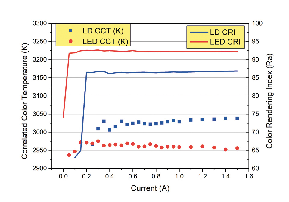
The spectrum (Figure 3) of the blue peak of the LARP prototype is much narrower and thus much more intense as opposed to the LED prototype. The blue peak for the LARP setup is approximately one order of magnitude above the blue LED emission peak. Correlated color temperature (CCT) has a value of 3025 and 2950 K for the LARP system and LED prototype respectively; Color Rendering Index has an average value of 86 and 92 respectively. CCT and CRI do not show any significant variation with the driving current as presented in figure 4, thus indicating a good stability of the light chromaticity at different driving conditions.
4. The lens should be placed in a dry and tidy place for testing and cleaning. There should be several layers of cleaning paper towels or wipes, and several sheets of cleaning tissues.


 Ms.Cici
 8618319014500