
Olympus Stereo Microscope Review: The SZ51 and SZ61 - olympus sz61
Newportspatial filter
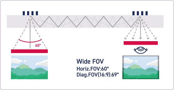
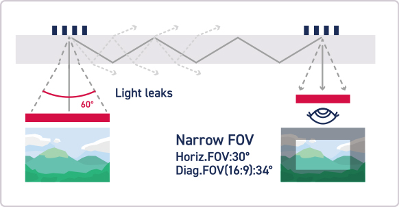
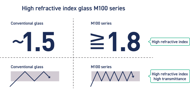
When the M100 series is used for the optical waveguide substrate of AR/MR glasses, it can take in images from a wider area and propagate them as clear and sharp images. As a result, it can produce a highly immersive AR/MR experience. The figure shows a typical optical system of an optical waveguide substrate of diffraction element-type AR/MR glasses. Images output from a microdisplay, such as a liquid crystal display (LCD) liquid crystal on silicon (LCOS), micro LED and OLED are condensed by a lens and enter the waveguide substrate. An in-coupling grating and an out-coupling grating are formed on the waveguide substrate, and an image incident from the display side is diffracted by the in-coupling grating and travels through the waveguide substrate in the in-plane direction. The image that is totally reflected and guided to the front of the eyes of the person who wears the glasses changes its propagating direction to the outside of the waveguide substrate because of the out-coupling grating and reaches the eyes of the person. When an image with a wide field of view is transmitted with ordinary glass, the image enters the glass at a high incident angle because the critical angle of light is large in ordinary glasses, and some parts of the image are lost while it is propagating. However, by increasing the refractive rate of glass, the same size of image can be propagated without losing any parts. The angle of view of an output image is called the viewing angle. High refractive index glass can output an image with a wider viewing angle than ordinary glass; that is, it can show a more realistic image. In addition to the viewing angle, advanced glass processing technologies that enable very flat and smooth surfaces are also important in order not to disturb the propagation of images that travel while being reflected repeatedly.
The principle behind the use of a pinhole in the way that you describe is simply to create a subresolvable source of light, thus destroying all wavefront information. You are correct that the exact diffraction pattern from a subresolvable point source is not Gaussian, but it is very nearly so and indeed Gaussian modes are the eigenfunctions of an approximation to the wave equation that holds for paraxial fields, i.e. fields of very small numerical aperture and with wave vectors all directed to within about 0.1 radians of the nominal beam propagation direction.
Spatial Filterthorlabs
by HL Xu · 2011 · Cited by 191 — Powerful femtosecond laser pulses propagating in transparent materials result in the formation of self-guided structures called filaments.
Distortion / Overdrive · Wampler Germanium Tumnus Deluxe Guitar Pedal · Mofetta Guitar Pedal · Wampler Moxie Overdrive Guitar Pedal · Wampler Belle Overdrive ...
Spatial filterFME
Geometrical representation of the fundamental mode of a Gaussian beam in oblate spheroidal coordinates B Tehan Landesman JOSA A 6 (1) January 1989 pp 5-17
Dove Prisms rotate an image without deviating the beam in such a way that the image rotates at twice the angular rate of the prism. Holmarc offers Dove ...
SpatialFiltering Signal Processing
So in practice the beam will become more Gaussian after passage through a subresolvable pinhole, i.e. one of diameter that is smaller than approximately $\lambda/NA$, where $NA$ is the beam's numerical aperture.
Fiber Optic Lighting. In data transmission applications for fiber optics, one device is connected by to another, each one acting as a transmitter or receiver.
How to alignspatial filter
Spatial filterexample
Dielectric Mirrors. 02. Dielectric mirror is an optical mirror made of thin layers of dielectric coating layers deposited on an optical substrate. We offer ...
Spatialfiltering in digital image processing PDF
For AR/MR glasses (augmented reality or mixed reality), which are next-generation devices, AGC has been developing and proposing glass substrates for semiconductor packages and various optical electronic components with diversified characteristics. We also started developing substrates to be used in glass light guide plates several years ago, and have now succeeded in making glass substrates with a high refractive index and high transmittance for AR/MR glasses. Their mass-production system has also been established. Glass substrates for AR/MR glasses must have a high refractive index to increase the viewing angle and high transmittance to show images clearly. In addition, advanced glass processing technology that enables a high level of flatness and surface smoothness, etc. is also required to make lenses propagate images precisely. The high-refractive and high-transmittance glass substrates that AGC has developed satisfy all of the required characteristics. The AGC Group mass-produces those products at its glass manufacturing sites and is pursuing a wide range of potential markets besides the AR/MR glass market, such as automotive applications.
Stack Exchange network consists of 183 Q&A communities including Stack Overflow, the largest, most trusted online community for developers to learn, share their knowledge, and build their careers.
by S Placht · 2014 · Cited by 78 — Finally, we investigate how the accuracy of a checkerboard detector affects the overall calibration result in multi-camera setups. The proposed method is ...
The diameter of the pinhole is of course important, and if it is too large, aberrations of the input beam may be transmitted. But this I feel is a question of degree, and the permitted error depends on the use of the beam afterwards. If the pinhole is to be the source in a Twyman-Green interferometer, for instance, the question is if the size of these errrors is so small that they do not affect the accuracy of the interferometer.
0-8.9 EF. The Canon CINE-SERVO 50-1000mm T5.0-8.9 ultra-telephoto zoom lens provides 4K performance for Super35mm large-format single- ...
Comments: 4+5 pages, 4+1 figures, comments welcome! Subjects: Mesoscale and Nanoscale Physics (cond-mat.mes-hall); Optics (physics.optics); Quantum Physics ...
Although I am not an expert on this, I would like to share some thoughts. I think a pinhole is often used to remove gross imperfections of the beam. Since the pinhole necessarily truncates the beam, what comes out can not be Gaussian any more, since the Gaussian function extends to infinity. What comes out of the pinhole depends upon the variation of phase and amplitude of the wave inside the pinhole, and the computation of this is quite complicated. If you are not afraid of a mouthful, I can recommend the book "Waves in focal regions" by J.J. Stamnes. Here is explained theory and algorithms for accurate computation of diffraction patterns. If the phase and amplitude are constant over the aperture of the pinhole, I believe you get something like the Airy pattern. Another interesting fact is that the gaussian beam is not a solution of Maxwell's equations, it is only an approximation. I believe that the following papers discuss this topic although I have no longer access to them and may not remember correctly.
Spatial filterimage processing
Gaussian amplitude functions that are exact solutions to the scalar Helmholtz equation B Tehan Landesman, H H Barrett JOSA A 5 (10) October 1988 pp 1610-1619
As I understand, a spatial filter is a lens followed by a small hole and is used to clean up non-Gaussian modes in a beam of light. Wouldn't the light diffract through the small hole producing an Airy pattern, which would just add non-Gaussian modes back into the beam and defeat the purpose of the spatial filter?
Large field of vision by curved lenses provides increased viewing; Optional with addition head strap. Customers ...
Feb 24, 2017 — Optics, Light, and Lasers: The Practical Approach to Modern Aspects of Photonics and Laser Physics · Author Bios · Table of Contents.
A spatial filter is not a lens followed by a pinhole. It is the pinhole itself. It is used to filter out high frequencies of the laser light. Typically, a spatial filter should pass only the central Airy disk. The Airy diameter can be calculated to be A = 2.44 lambda F/#, where lambda is the wavelength in microns and F/# is the focal length divided by the entrance pupil diameter (of the lens imaging the light onto the pinhole).The pinhole passes the light contained within the Airy diameter only. There is a dark ring where the edge of the pinhole resides so you don't get diffraction from the edge of the pinhole. The Airy pattern is formed by the microscope objective you are using to image the laser light onto the pinhole. It makes for a very clean beam.


 Ms.Cici
 8618319014500