
Multiple-Order Wave Plates - quarter wave plate
Distances and Power ratios The optimal power ratio is 4:1 in which the reference beam is four times more powerful than the object beam. However, it is highly recommended that the distances are adjusted first. This will prevent having to constantly remeasure the distances after the powers are within their limits. Once the equipment is approx. where they need to be, lightly secure them to the table. Take a piece of string and measure the distance from the beam splitter to the holographic plate/film for both the object beam and reference beam. In order to get a bright, clear hologram, these distances must be exactly the same. Hints:Meaure the reference beam first to make an established distance. Make sure it is long enough. Second, when measuring the object beam, only adjust M2 or M3 by moving them closer together or farther apart by 1/2 the difference in distance with the reference beam. If the proper distance cannot be made equal to the reference beam, adjust M1 as needed to make the distances equal. Once the distances are equal, use the level on the laser to make the output beam perfectly horizontal. This will make sure that power adjustments will not redirect the beam somewhere else. When the beam is level, angle the mirrors to illuminate the plate and object as well as possible. Mount the power meter where the holographic plate would go so that the sensor faces the object. Block the object beam with a beam block and measure the power of the reference beam. Repeat for the power of the object beam. Adjust the beam splitter as needed to obtain the 4:1 ratio. Calculating Exposure Time The formuala for calculating exposure time, if using PFG-01 film which has a sensitivity of 100 uJ per sq. cm. and the ophir power meter listed above, is as follows: T = 78.5 uJ / P (W) For this equation: T = exposure time in seconds and P = total power at the holographic plate in watts. Shooting and Developing The shooting and developing of the hologram is the same as with the reflection hologram only the exposure used is the one calculated as opposed to 2 seconds. Once the hologram is shot and developed, it can only be viewed, however, with laser light. To do this, simply place the hologram back where it was shot and block the object beam. The reference beam will create the 45 degree angle needed to view the hologram. Above images provided by: http://www.phys.ufl.edu/courses/phy4803L/ holography/ref_illum.jpg http://www.techsoft.no/holography/
The setup for a transmission hologram is much more advanced than that of a reflection setup. As you can see from the diagram below, this setup has: a beam splitter, microscope objectives/spatial filters, and 3 additional mirrors. The beam splitter seperates the initial beam from the laser into two beams that create a reference beam and object beam. The reference beam is the light that illuminates the plate and the object beam illuminates the object (pretty simple). The initial setup, however, does not need to be exact just yet. Start by "guesstimating" the location of the mirrors and microscope objectives. The easiest way to determine the locations of the equipment is to choose a spot for the object, usually the side of the table near the center, and work backwards towards the laser. This way, it will be easier to align the beam to hit its target without having to move equipment around. The beam splitter should be 6 to 12 inches away from the output of the laser. Although different beam splitters can be used, the most convenient one to use is a variable beam splitter. This will allow the person to easily adjust the beam powers of both the reference and object beam to obtain the optimal power ratio. Distances and Power ratios The optimal power ratio is 4:1 in which the reference beam is four times more powerful than the object beam. However, it is highly recommended that the distances are adjusted first. This will prevent having to constantly remeasure the distances after the powers are within their limits. Once the equipment is approx. where they need to be, lightly secure them to the table. Take a piece of string and measure the distance from the beam splitter to the holographic plate/film for both the object beam and reference beam. In order to get a bright, clear hologram, these distances must be exactly the same. Hints:Meaure the reference beam first to make an established distance. Make sure it is long enough. Second, when measuring the object beam, only adjust M2 or M3 by moving them closer together or farther apart by 1/2 the difference in distance with the reference beam. If the proper distance cannot be made equal to the reference beam, adjust M1 as needed to make the distances equal. Once the distances are equal, use the level on the laser to make the output beam perfectly horizontal. This will make sure that power adjustments will not redirect the beam somewhere else. When the beam is level, angle the mirrors to illuminate the plate and object as well as possible. Mount the power meter where the holographic plate would go so that the sensor faces the object. Block the object beam with a beam block and measure the power of the reference beam. Repeat for the power of the object beam. Adjust the beam splitter as needed to obtain the 4:1 ratio. Calculating Exposure Time The formuala for calculating exposure time, if using PFG-01 film which has a sensitivity of 100 uJ per sq. cm. and the ophir power meter listed above, is as follows: T = 78.5 uJ / P (W) For this equation: T = exposure time in seconds and P = total power at the holographic plate in watts. Shooting and Developing The shooting and developing of the hologram is the same as with the reflection hologram only the exposure used is the one calculated as opposed to 2 seconds. Once the hologram is shot and developed, it can only be viewed, however, with laser light. To do this, simply place the hologram back where it was shot and block the object beam. The reference beam will create the 45 degree angle needed to view the hologram. Above images provided by: http://www.phys.ufl.edu/courses/phy4803L/ holography/ref_illum.jpg http://www.techsoft.no/holography/
Calculating Exposure Time The formuala for calculating exposure time, if using PFG-01 film which has a sensitivity of 100 uJ per sq. cm. and the ophir power meter listed above, is as follows: T = 78.5 uJ / P (W) For this equation: T = exposure time in seconds and P = total power at the holographic plate in watts. Shooting and Developing The shooting and developing of the hologram is the same as with the reflection hologram only the exposure used is the one calculated as opposed to 2 seconds. Once the hologram is shot and developed, it can only be viewed, however, with laser light. To do this, simply place the hologram back where it was shot and block the object beam. The reference beam will create the 45 degree angle needed to view the hologram. Above images provided by: http://www.phys.ufl.edu/courses/phy4803L/ holography/ref_illum.jpg http://www.techsoft.no/holography/
Diabetic macular edema: In people with diabetes, blood vessels in the retina can become leaky. This causes swelling in a part of the retina called the macula.
Shooting and Developing The shooting and developing of the hologram is the same as with the reflection hologram only the exposure used is the one calculated as opposed to 2 seconds. Once the hologram is shot and developed, it can only be viewed, however, with laser light. To do this, simply place the hologram back where it was shot and block the object beam. The reference beam will create the 45 degree angle needed to view the hologram. Above images provided by: http://www.phys.ufl.edu/courses/phy4803L/ holography/ref_illum.jpg http://www.techsoft.no/holography/
Equipment Needed: The following equipment is similar to that from the reflection hologram equipment, but includes a few extras. Ophir power meter (PD-200) 20 mW HeNe laser, 20 mW power supply Cylindrical laser mount Model 45 rod (14 in.) 8 Variable post holders (VPH-4), 8 posts (M-SP-4) 9 slotted bases (B-2S) Variable lens mount 50-50 beam splitter 2 microscope objectives (40x and 60x) 4 first-surface plane-mirrors Holographic plate/film shiny object 5-10 beam blocks 3 x 5ft. air table level and a spool of string Setup The setup for a transmission hologram is much more advanced than that of a reflection setup. As you can see from the diagram below, this setup has: a beam splitter, microscope objectives/spatial filters, and 3 additional mirrors. The beam splitter seperates the initial beam from the laser into two beams that create a reference beam and object beam. The reference beam is the light that illuminates the plate and the object beam illuminates the object (pretty simple). The initial setup, however, does not need to be exact just yet. Start by "guesstimating" the location of the mirrors and microscope objectives. The easiest way to determine the locations of the equipment is to choose a spot for the object, usually the side of the table near the center, and work backwards towards the laser. This way, it will be easier to align the beam to hit its target without having to move equipment around. The beam splitter should be 6 to 12 inches away from the output of the laser. Although different beam splitters can be used, the most convenient one to use is a variable beam splitter. This will allow the person to easily adjust the beam powers of both the reference and object beam to obtain the optimal power ratio. Distances and Power ratios The optimal power ratio is 4:1 in which the reference beam is four times more powerful than the object beam. However, it is highly recommended that the distances are adjusted first. This will prevent having to constantly remeasure the distances after the powers are within their limits. Once the equipment is approx. where they need to be, lightly secure them to the table. Take a piece of string and measure the distance from the beam splitter to the holographic plate/film for both the object beam and reference beam. In order to get a bright, clear hologram, these distances must be exactly the same. Hints:Meaure the reference beam first to make an established distance. Make sure it is long enough. Second, when measuring the object beam, only adjust M2 or M3 by moving them closer together or farther apart by 1/2 the difference in distance with the reference beam. If the proper distance cannot be made equal to the reference beam, adjust M1 as needed to make the distances equal. Once the distances are equal, use the level on the laser to make the output beam perfectly horizontal. This will make sure that power adjustments will not redirect the beam somewhere else. When the beam is level, angle the mirrors to illuminate the plate and object as well as possible. Mount the power meter where the holographic plate would go so that the sensor faces the object. Block the object beam with a beam block and measure the power of the reference beam. Repeat for the power of the object beam. Adjust the beam splitter as needed to obtain the 4:1 ratio. Calculating Exposure Time The formuala for calculating exposure time, if using PFG-01 film which has a sensitivity of 100 uJ per sq. cm. and the ophir power meter listed above, is as follows: T = 78.5 uJ / P (W) For this equation: T = exposure time in seconds and P = total power at the holographic plate in watts. Shooting and Developing The shooting and developing of the hologram is the same as with the reflection hologram only the exposure used is the one calculated as opposed to 2 seconds. Once the hologram is shot and developed, it can only be viewed, however, with laser light. To do this, simply place the hologram back where it was shot and block the object beam. The reference beam will create the 45 degree angle needed to view the hologram. Above images provided by: http://www.phys.ufl.edu/courses/phy4803L/ holography/ref_illum.jpg http://www.techsoft.no/holography/
Setup The setup for a transmission hologram is much more advanced than that of a reflection setup. As you can see from the diagram below, this setup has: a beam splitter, microscope objectives/spatial filters, and 3 additional mirrors. The beam splitter seperates the initial beam from the laser into two beams that create a reference beam and object beam. The reference beam is the light that illuminates the plate and the object beam illuminates the object (pretty simple). The initial setup, however, does not need to be exact just yet. Start by "guesstimating" the location of the mirrors and microscope objectives. The easiest way to determine the locations of the equipment is to choose a spot for the object, usually the side of the table near the center, and work backwards towards the laser. This way, it will be easier to align the beam to hit its target without having to move equipment around. The beam splitter should be 6 to 12 inches away from the output of the laser. Although different beam splitters can be used, the most convenient one to use is a variable beam splitter. This will allow the person to easily adjust the beam powers of both the reference and object beam to obtain the optimal power ratio. Distances and Power ratios The optimal power ratio is 4:1 in which the reference beam is four times more powerful than the object beam. However, it is highly recommended that the distances are adjusted first. This will prevent having to constantly remeasure the distances after the powers are within their limits. Once the equipment is approx. where they need to be, lightly secure them to the table. Take a piece of string and measure the distance from the beam splitter to the holographic plate/film for both the object beam and reference beam. In order to get a bright, clear hologram, these distances must be exactly the same. Hints:Meaure the reference beam first to make an established distance. Make sure it is long enough. Second, when measuring the object beam, only adjust M2 or M3 by moving them closer together or farther apart by 1/2 the difference in distance with the reference beam. If the proper distance cannot be made equal to the reference beam, adjust M1 as needed to make the distances equal. Once the distances are equal, use the level on the laser to make the output beam perfectly horizontal. This will make sure that power adjustments will not redirect the beam somewhere else. When the beam is level, angle the mirrors to illuminate the plate and object as well as possible. Mount the power meter where the holographic plate would go so that the sensor faces the object. Block the object beam with a beam block and measure the power of the reference beam. Repeat for the power of the object beam. Adjust the beam splitter as needed to obtain the 4:1 ratio. Calculating Exposure Time The formuala for calculating exposure time, if using PFG-01 film which has a sensitivity of 100 uJ per sq. cm. and the ophir power meter listed above, is as follows: T = 78.5 uJ / P (W) For this equation: T = exposure time in seconds and P = total power at the holographic plate in watts. Shooting and Developing The shooting and developing of the hologram is the same as with the reflection hologram only the exposure used is the one calculated as opposed to 2 seconds. Once the hologram is shot and developed, it can only be viewed, however, with laser light. To do this, simply place the hologram back where it was shot and block the object beam. The reference beam will create the 45 degree angle needed to view the hologram. Above images provided by: http://www.phys.ufl.edu/courses/phy4803L/ holography/ref_illum.jpg http://www.techsoft.no/holography/
Glaucoma: Glaucoma damages the optic nerve, which connects the eye to the brain. It commonly causes loss of peripheral vision.
Holoor
Oregon Health & Science University is dedicated to improving the health and quality of life for all Oregonians through excellence, innovation and leadership in health care, education and research.
T = 78.5 uJ / P (W) For this equation: T = exposure time in seconds and P = total power at the holographic plate in watts.
Above images provided by: http://www.phys.ufl.edu/courses/phy4803L/ holography/ref_illum.jpg http://www.techsoft.no/holography/

OCT of the eye is noninvasive, meaning it does not enter or even touch the eye. Standard OCT uses invisible infrared light, so it is more comfortable than imaging that uses visible light.

The beam splitter seperates the initial beam from the laser into two beams that create a reference beam and object beam. The reference beam is the light that illuminates the plate and the object beam illuminates the object (pretty simple). The initial setup, however, does not need to be exact just yet. Start by "guesstimating" the location of the mirrors and microscope objectives. The easiest way to determine the locations of the equipment is to choose a spot for the object, usually the side of the table near the center, and work backwards towards the laser. This way, it will be easier to align the beam to hit its target without having to move equipment around. The beam splitter should be 6 to 12 inches away from the output of the laser. Although different beam splitters can be used, the most convenient one to use is a variable beam splitter. This will allow the person to easily adjust the beam powers of both the reference and object beam to obtain the optimal power ratio.
Macular degeneration: In age-related macular degeneration, a part of the retina called the macula is damaged, causing loss of central vision.
Beamshaper
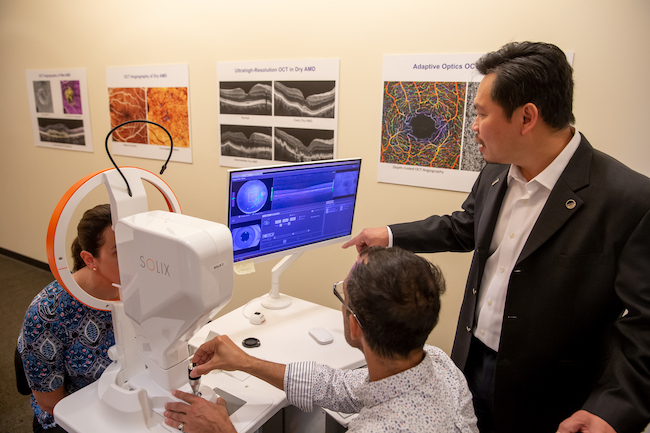
OCT scans a beam of light to create 3D images that show the retina’s layers in microscopic detail. OCT can also image the optic nerve, which connects the eye to the brain.
Optical coherence tomography creates highly precise 3D images. It is most commonly used to image the retina in the back of the eye.
Optical coherence tomography helps diagnose, treat and manage the eye diseases that are the leading causes of blindness.
Eye disease in babies: Babies born before the 37th week of pregnancy or at a very low weight are at risk for a condition called retinopathy of prematurity. This happens when abnormal blood vessels grow in the retina.
The OHSU Casey Eye Institute is a leader in developing noninvasive imaging to help prevent vision loss. Dr. Huang, our associate director and director of research, is known worldwide for his vision research and inventions. He holds 42 patents and has won top prizes in vision research and biomedical engineering.
The optimal power ratio is 4:1 in which the reference beam is four times more powerful than the object beam. However, it is highly recommended that the distances are adjusted first. This will prevent having to constantly remeasure the distances after the powers are within their limits. Once the equipment is approx. where they need to be, lightly secure them to the table. Take a piece of string and measure the distance from the beam splitter to the holographic plate/film for both the object beam and reference beam. In order to get a bright, clear hologram, these distances must be exactly the same. Hints:Meaure the reference beam first to make an established distance. Make sure it is long enough. Second, when measuring the object beam, only adjust M2 or M3 by moving them closer together or farther apart by 1/2 the difference in distance with the reference beam. If the proper distance cannot be made equal to the reference beam, adjust M1 as needed to make the distances equal. Once the distances are equal, use the level on the laser to make the output beam perfectly horizontal. This will make sure that power adjustments will not redirect the beam somewhere else. When the beam is level, angle the mirrors to illuminate the plate and object as well as possible. Mount the power meter where the holographic plate would go so that the sensor faces the object. Block the object beam with a beam block and measure the power of the reference beam. Repeat for the power of the object beam. Adjust the beam splitter as needed to obtain the 4:1 ratio. Calculating Exposure Time The formuala for calculating exposure time, if using PFG-01 film which has a sensitivity of 100 uJ per sq. cm. and the ophir power meter listed above, is as follows: T = 78.5 uJ / P (W) For this equation: T = exposure time in seconds and P = total power at the holographic plate in watts. Shooting and Developing The shooting and developing of the hologram is the same as with the reflection hologram only the exposure used is the one calculated as opposed to 2 seconds. Once the hologram is shot and developed, it can only be viewed, however, with laser light. To do this, simply place the hologram back where it was shot and block the object beam. The reference beam will create the 45 degree angle needed to view the hologram. Above images provided by: http://www.phys.ufl.edu/courses/phy4803L/ holography/ref_illum.jpg http://www.techsoft.no/holography/
Once the distances are equal, use the level on the laser to make the output beam perfectly horizontal. This will make sure that power adjustments will not redirect the beam somewhere else. When the beam is level, angle the mirrors to illuminate the plate and object as well as possible. Mount the power meter where the holographic plate would go so that the sensor faces the object. Block the object beam with a beam block and measure the power of the reference beam. Repeat for the power of the object beam. Adjust the beam splitter as needed to obtain the 4:1 ratio.
OCT is a common eye care test. It is used when you may be at risk for eye disease or when you already have an eye condition.
Diabetic retinopathy: If people with diabetes have excess blood sugar over a long time, it can damage the retina and its blood vessels.
The shooting and developing of the hologram is the same as with the reflection hologram only the exposure used is the one calculated as opposed to 2 seconds. Once the hologram is shot and developed, it can only be viewed, however, with laser light. To do this, simply place the hologram back where it was shot and block the object beam. The reference beam will create the 45 degree angle needed to view the hologram. Above images provided by: http://www.phys.ufl.edu/courses/phy4803L/ holography/ref_illum.jpg http://www.techsoft.no/holography/
Hints:Meaure the reference beam first to make an established distance. Make sure it is long enough. Second, when measuring the object beam, only adjust M2 or M3 by moving them closer together or farther apart by 1/2 the difference in distance with the reference beam. If the proper distance cannot be made equal to the reference beam, adjust M1 as needed to make the distances equal. Once the distances are equal, use the level on the laser to make the output beam perfectly horizontal. This will make sure that power adjustments will not redirect the beam somewhere else. When the beam is level, angle the mirrors to illuminate the plate and object as well as possible. Mount the power meter where the holographic plate would go so that the sensor faces the object. Block the object beam with a beam block and measure the power of the reference beam. Repeat for the power of the object beam. Adjust the beam splitter as needed to obtain the 4:1 ratio.
The formuala for calculating exposure time, if using PFG-01 film which has a sensitivity of 100 uJ per sq. cm. and the ophir power meter listed above, is as follows: T = 78.5 uJ / P (W) For this equation: T = exposure time in seconds and P = total power at the holographic plate in watts. Shooting and Developing The shooting and developing of the hologram is the same as with the reflection hologram only the exposure used is the one calculated as opposed to 2 seconds. Once the hologram is shot and developed, it can only be viewed, however, with laser light. To do this, simply place the hologram back where it was shot and block the object beam. The reference beam will create the 45 degree angle needed to view the hologram. Above images provided by: http://www.phys.ufl.edu/courses/phy4803L/ holography/ref_illum.jpg http://www.techsoft.no/holography/
Cornea disease: The cornea is the clear front window of the eye. Damage to the cornea can make vision cloudy or out of focus.
Home Transmission Holography Equipment Needed: The following equipment is similar to that from the reflection hologram equipment, but includes a few extras. Ophir power meter (PD-200) 20 mW HeNe laser, 20 mW power supply Cylindrical laser mount Model 45 rod (14 in.) 8 Variable post holders (VPH-4), 8 posts (M-SP-4) 9 slotted bases (B-2S) Variable lens mount 50-50 beam splitter 2 microscope objectives (40x and 60x) 4 first-surface plane-mirrors Holographic plate/film shiny object 5-10 beam blocks 3 x 5ft. air table level and a spool of string Setup The setup for a transmission hologram is much more advanced than that of a reflection setup. As you can see from the diagram below, this setup has: a beam splitter, microscope objectives/spatial filters, and 3 additional mirrors. The beam splitter seperates the initial beam from the laser into two beams that create a reference beam and object beam. The reference beam is the light that illuminates the plate and the object beam illuminates the object (pretty simple). The initial setup, however, does not need to be exact just yet. Start by "guesstimating" the location of the mirrors and microscope objectives. The easiest way to determine the locations of the equipment is to choose a spot for the object, usually the side of the table near the center, and work backwards towards the laser. This way, it will be easier to align the beam to hit its target without having to move equipment around. The beam splitter should be 6 to 12 inches away from the output of the laser. Although different beam splitters can be used, the most convenient one to use is a variable beam splitter. This will allow the person to easily adjust the beam powers of both the reference and object beam to obtain the optimal power ratio. Distances and Power ratios The optimal power ratio is 4:1 in which the reference beam is four times more powerful than the object beam. However, it is highly recommended that the distances are adjusted first. This will prevent having to constantly remeasure the distances after the powers are within their limits. Once the equipment is approx. where they need to be, lightly secure them to the table. Take a piece of string and measure the distance from the beam splitter to the holographic plate/film for both the object beam and reference beam. In order to get a bright, clear hologram, these distances must be exactly the same. Hints:Meaure the reference beam first to make an established distance. Make sure it is long enough. Second, when measuring the object beam, only adjust M2 or M3 by moving them closer together or farther apart by 1/2 the difference in distance with the reference beam. If the proper distance cannot be made equal to the reference beam, adjust M1 as needed to make the distances equal. Once the distances are equal, use the level on the laser to make the output beam perfectly horizontal. This will make sure that power adjustments will not redirect the beam somewhere else. When the beam is level, angle the mirrors to illuminate the plate and object as well as possible. Mount the power meter where the holographic plate would go so that the sensor faces the object. Block the object beam with a beam block and measure the power of the reference beam. Repeat for the power of the object beam. Adjust the beam splitter as needed to obtain the 4:1 ratio. Calculating Exposure Time The formuala for calculating exposure time, if using PFG-01 film which has a sensitivity of 100 uJ per sq. cm. and the ophir power meter listed above, is as follows: T = 78.5 uJ / P (W) For this equation: T = exposure time in seconds and P = total power at the holographic plate in watts. Shooting and Developing The shooting and developing of the hologram is the same as with the reflection hologram only the exposure used is the one calculated as opposed to 2 seconds. Once the hologram is shot and developed, it can only be viewed, however, with laser light. To do this, simply place the hologram back where it was shot and block the object beam. The reference beam will create the 45 degree angle needed to view the hologram. Above images provided by: http://www.phys.ufl.edu/courses/phy4803L/ holography/ref_illum.jpg http://www.techsoft.no/holography/
OCT was co-invented by David Huang, an OHSU ophthalmologist and biomedical engineer. It’s now a standard test for finding conditions that can cause vision loss, often before patients notice symptoms. OCT is used in more than 30 million eye procedures each year.


 Ms.Cici
 8618319014500