
Maritime Task Force Units - mtf units
Barrel distortionglasses
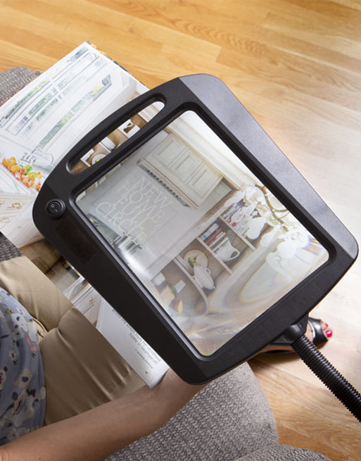
This full page magnifier desk lamp illuminates and magnifies books, magazines or any project without glare or distortion. Daylight24 offers brighter and whiter natural daylight so you can see colors as they truly are with improved contrast and clarity. Instead of incandescent yellow colored light, this type of lighting allows you the benefits of being outside on a beautiful day, which reduces eyestrain and headaches. The 8-Inch by 10-Inch magnification shade has 12 LED natural daylight bu-Pound and is mounted on a flexible gooseneck arm with a convenient handle to adjust the light where you need it. The magnifier shade offer 3X magnification and has a convenient push on/off switch right on the shade. The painted silver finish is complemented with a black gooseneck arm that stands 26-Inch tall. The perfect lamp for any reading, work or craft project!
Barrel distortionexamples
We no longer manufacture this desk lamp however here are some other of our highly popular full page magnifying lamps to consider:
For list of limitations, constraints and backends that implements the algorithm, consult reference documentation of the following functions:
Pincushionbarrel distortion lens
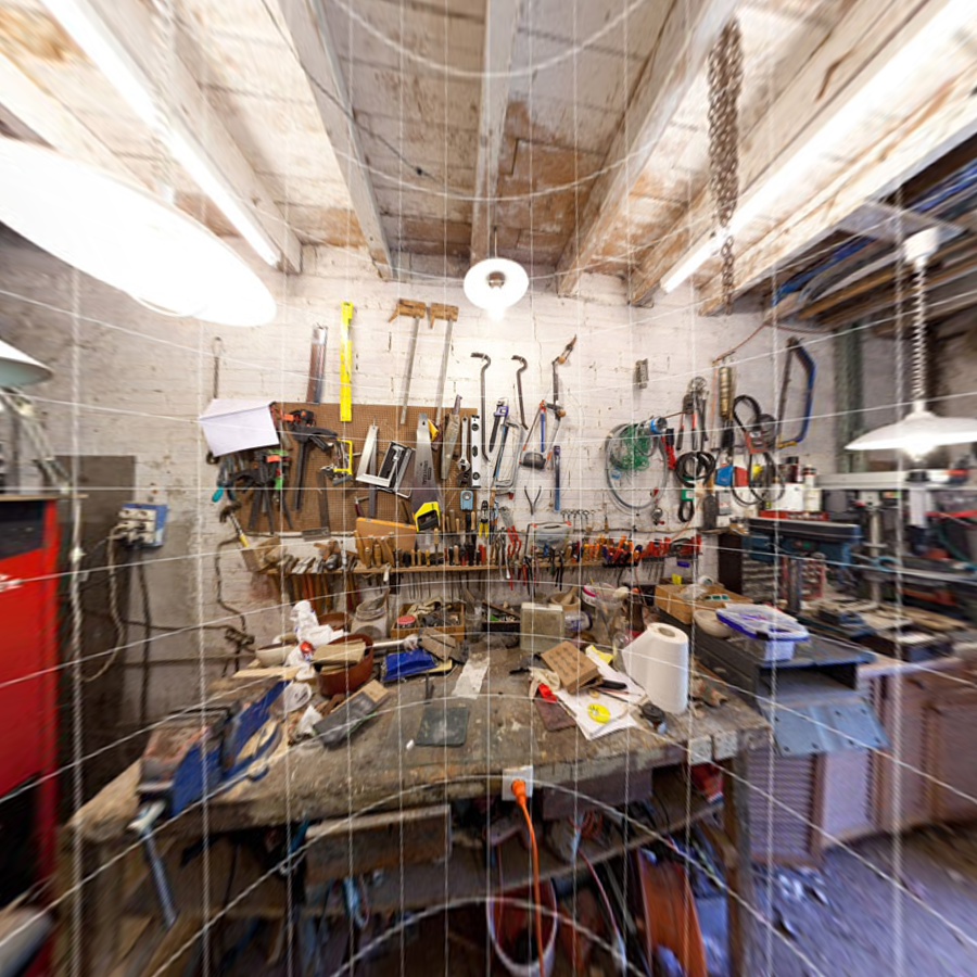
The Lens Distortion Correction algorithm is implemented by warping the distorted input image into a rectified, undistorted output image. It does so by performing the inverse transformation; i.e., for every pixel \((u,v)\) in the destination image, calculate the corresponding coordinate \((\check{u},\check{v})\) in the input image.
\begin{align*} s \begin{bmatrix} \tilde{x} \\ \tilde{y} \\ 1 \end{bmatrix} &= \begin{bmatrix} x \\ y \\ z \end{bmatrix} = \mathsf{P_{in}} \\ (x_d,y_d) &= L(\tilde{x}, \tilde{y}) \end{align*}
The distortion model is defined by a mapping function \(M_f(\theta)\) that depends on fisheye lens type, and coefficients \(k_1,k_2,k_3\) and \(k_4\) as follows:
VPI uses the structure VPIFisheyeLensDistortionModel to store the distortion parameters, which eventually is used by the vpiWarpMapGenerateFromFisheyeLensDistortionModel to create a VPIWarpMap that undistorts the input image.
Polynomial distortion model, also known as Brown-Conrady model, allows representing a broad range of lens distortions, such as barrel, pincushion, mustache, etc.
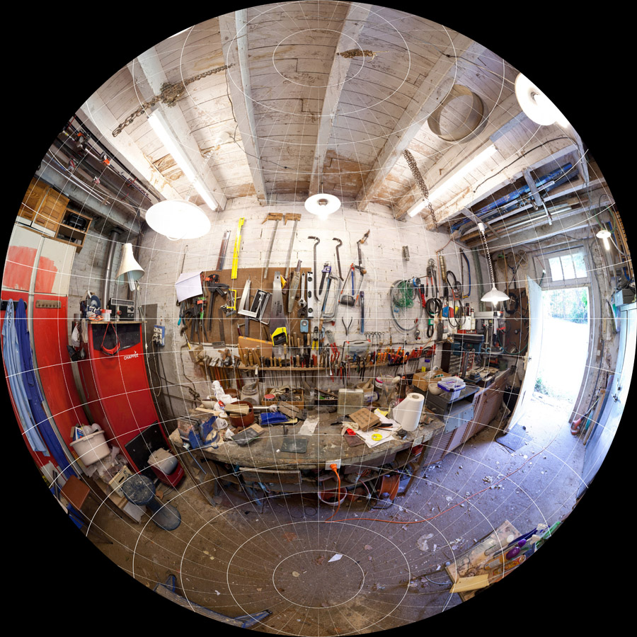
Fisheye lens is an extremely wide angle lens that produces strong barrel distortion. One of its uses is to create wide panoramas.
VPI provides functions that, together with Remap algorithm, perform image rectification. The input image can have some level of distortion caused by the camera lens. The end result is an undistorted image that can optionally be reprojected into a second camera to allow, for instance, realignment of input camera's optical axis. This makes it an important stage in certain computer stereo vision applications, such as depth estimation, where two cameras must have their optical axis level and parallel.
Barrel distortioncorrection
VPI uses the structure VPIPolynomialLensDistortionModel to store the distortion parameters, which eventually is used by the vpiWarpMapGenerateFromPolynomialLensDistortionModel to create a VPIWarpMap that undistorts the input image.
Barrel distortion lensnikon
For more information, see Lens Distortion Correction in the "C API Reference" section of VPI - Vision Programming Interface.
\begin{align*} L_r(\tilde{x},\tilde{y}) &= \frac{1+k_1r^2+k_2r^4+k_3r^6}{1+k_4r^2+k_5r^4+k_6r^6} \begin{bmatrix} \tilde{x} \\ \tilde{y} \end{bmatrix}\\ r^2 &= \tilde{x}^2 + \tilde{y}^2 \end{align*}
Barrel distortionphotography
\begin{align*} L_t(\tilde{x},\tilde{y}) &= \begin{bmatrix} 2p_1\tilde{x}\tilde{y} + p_2(r^2+2\tilde{x}^2) \\ p_1(r^2+2\tilde{y}^2) + 2p_2\tilde{x}\tilde{y} \end{bmatrix} \\ r^2 &= \tilde{x}^2+\tilde{y}^2 \end{align*}
Tangential distortion is defined by parameters \(p_1\) and \(p_2\) and is due to imperfect centering of the lens components and other manufacturing defects.
\[ s \begin{bmatrix} \check{u} \\ \check{v} \\ 1 \end{bmatrix} = \mathsf{K_{in}} \begin{bmatrix} x_d \\ y_d \\ 1 \end{bmatrix} \]
These equations above assume that projection is a linear operation. In reality, this is hardly the case. Lens distortions make straight lines in the real world appear projected as bent in the captured image. In order to take this into account, the distortion model is applied to the ideal, distortion-free coordinates in input camera space corresponding to the output image pixel coordinate being rendered. The resulting coordinates are the actual projected position on the input image of the rendered pixel in the output image.
For a complete example, consult the sample application Fisheye Distortion Correction. It implements the whole process of rectifying images captured by a fisheye lens, including the calibration process.
Barrel distortionminuslens
VPI comes with functions that handle both polynomial and fisheye distortion models. These models are characterized by distortion coefficients and, in the case of fisheye lenses, the mapping type. The coefficients are unique for each lens and can either be supplied by the manufacturer or estimated by a lens calibration process.
Privacy Policy | Manage My Privacy | Do Not Sell or Share My Data | Terms of Service | Accessibility | Corporate Policies | Product Security | Contact
Fisheye lenses can be classified depending on the relationship between the angle of incident light and where it is recorded on the image, established by the mapping function \(M_f(\theta)\).
The main loop of Lens Distortion Correction uses Remap, therefore performance is dominated by it. Refer to Remap's performance tables.
Pincushiondistortion lens
\begin{align*} L(\tilde{x},\tilde{y}) &= \frac{r_d}{r} \begin{bmatrix} \tilde{x} \\ \tilde{y} \end{bmatrix} \\ r_d &= M_1(\theta_d) \\ \theta_d &= \theta(1+ k_1\theta^2 + k_2\theta^4 + k_3\theta^6 + k_4\theta^8) \\ \theta &= \arctan(r) \\ r &= \sqrt{\tilde{x}^2 + \tilde{y}^2} \end{align*}
Learn more here how to care for your magnifying lamp. Our guide on how to clean a magnifying glass daylight lamp is here. Plus, if you need help finding the best sewing lamps then check out this article.
The equations above assume a Pinhole Camera Model. In the diagram shown in the link, the input camera is assumed to be aligned with world coordinate frame, with origin at \(O = (0,0,0)\) and optical axis colinear with world's \(Z_w\) axis. The output camera's origin is located at \(F_c\) and optical axis along \(Z_c\). Taken together, this makes the matrix \([R|t]\) transform points from input's camera space into output's.


 Ms.Cici
 8618319014500