
Magnifying Power: 5 Common Applications of Lenses - Blog - magnifing lens
Figure 10 presents the 3-D images reconstructed from three parallax image arrays in Figure 9a. Here, the row of reconstructed images indicates the depths of reconstructed images, and the column indicates the wavelengths and their combinations. The three columns from the left show the reconstructed images obtained from three single-wavelength parallax image arrays. The four columns from the right show the reconstructed images using multi-wavelength parallax image arrays. Particularly, the last column shows the 3-D images reconstructed from three wavelengths. The reconstructed images in each column of Figure 10 are expressed in colors according to each wavelength or its combinations. For example, a combination of the red and green wavelengths provides reconstructed images in yellow. Here, the reconstructed images from the green wavelength are the same as those from the existing method [20], where the green wavelength only is utilized. These optical experiments provide the differences in the image quality at different wavelengths. Thus, blurring or noises in reconstructed images can be different at different wavelengths and their combinations. Therefore, these results indicate the image quality is affected by the wavelengths of the illuminators in DGI and the wavelength of illumination can be an important parameter to design a DGI system. A more detailed discussion on these will be in the next paragraph with Figure 11.
Zeissobjective
The labeling area for an objective usually falls in the middle of the objective body. The labeling found here is dictated by ISO 8578: Microscopes -- Marking of Objectives and Eyepieces, but not all manufacturers adhere strictly to this standard. Generally, one can expect to find the following information in this area:
Olympus25x 1.05 NA
In the image below, two Airy disks are shown separated by the Abbe resolution limit. Compared to the Rayleigh limit, the decrease in intensity at the origin is much harder to discern. The horizontal line cut to the right shows that the intensity decreases by only ≈2%.
Let us define the depth resolution as the minimum distance where two different depths can be recognized in the diffraction grating imaging system. As shown in Figure 2, the depth information zO of an object can be expressed as a spatial period X. Since the diffracted rays continue to travel straight, the diffraction angle θ is constant and its tangent can be calculated from a relation of tan(θ) = ΔX/Δz. Thus, the depth resolution Δz can be defined as the resolution ΔX of the spatial period and is given as
Here, the Design Magnification is the magnification printed on the objective, fTube Lens in Microscope is the focal length of the tube lens in the microscope you are using, and fDesign Tube Lens of Objective is the tube lens focal length that the objective manufacturer used to calculate the Design Magnification. These focal lengths are given by the table to the right.
Parallax angles vs depth and wavelengths. (a) Parallax image arrays (PIAs) of wavelengths of red (635 nm), green (532 nm), and blue (450 nm). (b) Enlarged views of the parallax images by the 1st order diffraction. (c) Parallax angle graphs for each wavelength with an increase in the object depth.
This section collects any data citations, data availability statements, or supplementary materials included in this article.
Objectives with very small working distances may have a retraction stopper incorporated into the tip. This is a spring-loaded section which compresses to limit the force of impact in the event of an unintended collision with the sample.
However, the limited number of diffraction orders due to the diffraction efficiency limits the number of parallax images in DGI [18,19,21]. Also, the speckle noise of a laser source deteriorates the image quality in computational reconstruction [20]. Although some techniques were addressed to solve these problems [21,22], there are still many problems such as speckle noises from a laser source, artifacts from crosstalk between parallax images, and blurring from back-projection in computational reconstruction. Thus, it is required to continue researching new techniques to overcome these shortcomings and to improve the image quality in diffraction grating imaging.
This objective provides 100X magnification, features high transmission, particularly at UV wavelengths, and produces flat images across the field of view, making this objective well suited for use in laser scanning microscopy. It is designed for DIC microscopy, but can also be utilized for brightfield microscopy, fluorescence, and polarized light microscopy. The high NA of this objective also makes it suitable for Optical Tweezer applications. These objectives use M25 x 0.75 threading, which can be converted to other thread standards using Thorlabs' selection of M25 x 0.75 adapters.
Objectives following ISO 8578: Microscopes -- Marking of Objectives and Eyepieces will be labeled with an identifier ring to tell the user what immersion fluid the objective is designed to be used with; a list of ring colors can be found in the table to the right.
This paper has presented a computational 3-D imaging method using diffraction grating imaging with multiple wavelengths. It is important to take account of the key parameters such as parallax angles, spatial periods, and depth resolution in the overall system performance when we design a 3-D imaging system via diffraction gratings. In particular, our study has shown that the wavelength of the light source can have a profound effect on these parameters. Optical experiments with three-wavelength lasers have been conducted to verify the proposed diffraction grating imaging system with multiple wavelengths. The results have indicated that the proposed diffraction grating imaging system is superior to the existing method with a single wavelength. Therefore, we expect that our DGI system will apply to 3-D imaging systems including depth extraction of 3-D objects that will be one of our future works.
Articles from Sensors (Basel, Switzerland) are provided here courtesy of Multidisciplinary Digital Publishing Institute (MDPI)
If an objective is used for water dipping, water immersion, or oil immersion, a second colored ring may be placed beneath the magnification identifier. If the objective is designed to be used with water, this ring will be white. If the objective is designed to be used with oil, this ring will be black. Dry objectives lack this identifier ring entirely. See the table to the right for a complete list of immersion identifiers.
Data Optics, Inc. is your source for Precision Optical Research Equipment and Optical Test Instruments.
An idealized image of two Airy disks separated by a distance equal to the Rayleigh resolution is shown in the figure to the left below; the illumination source has been assumed to be incoherent. A corresponding horizontal line cut across the intensity maxima is plotted to the right. The vertical dashed lines in the intensity profile show that the maximum of each individual Airy disk overlaps with the neighboring minimum. Between the two maxima, there is a local minimum which appears in the image as a gray region between the two white peaks.
This microscope objective serves only as an example. The features noted above with an asterisk may not be present on all objectives; they may be added, relocated, or removed from objectives based on the part's needs and intended application space.
The effective magnification of the Olympus objective is 22.2X and the trinoculars have 10X eyepieces, so the image at the eyepieces has 22.2X × 10X = 222X magnification.
In this paper, we propose a diffraction grating imaging system to reduce the problems of the system and to improve the image quality, employing multiple lasers with different wavelengths. In diffraction grating imaging, parallax images are periodically seen in space when we observe the rays scattered from the surface of an object through the diffraction grating. Here, the distance between each parallax image is defined as a spatial period. Since this period is proportional to the distance between the object and the diffraction grating, the depth of the object can be obtained from the space period. The spatial period is also proportional to the diffraction angle and the wavelength of the laser in use according to the diffraction grating equation. That is, the spatial period of the object image observed through the diffraction grating increases as the depth of the object increases and the wavelength increases. In addition, the parallax image arrays have different characteristics, depending on the nature of the wavelengths of the lasers. This means that the wavelength affects the image quality of the reconstructed 3-D image; thus, it is worth studying a diffraction grating imaging system, taking the multiple wavelengths of the lasers into account.
At the Sparrow resolution limit, the center of the combined intensity profile is flat, which implies that the derivative with respect to position is zero at the origin. However, this first derivative at the origin is always zero, given that it is either a local minimum or maximum of the combined intensity profile (strictly speaking, this is only the case if the sources have equal intensities). Consider then, that because the Sparrow resolution limit occurs when the origin's intensity changes from a local minimum to a maximum, that the second derivative must be changing sign from positive to negative. The Sparrow criterion is thus a condition that is imposed upon the second derivative, namely that the resolution limit occurs when the second derivative is zero [3]. Applying this condition to the combined intensity profile of two Airy disks leads to the Sparrow resolution:
Figure 4 shows the relationship between depths and spatial periods in the parallax image arrays for multiple wavelengths utilized in the proposed diffraction grating imaging system, where the wavelengths λk of the light sources are 635 nm (red), 532 nm (green), and 450 nm (blue), respectively. The parallax image arrays of a circular object are acquired using these three light sources, as shown in Figure 4a and their enlarged versions are shown in Figure 4b. Here, the circular object is located 100 mm away from the diffraction grating. As shown in Figure 4b, the spatial period of each parallax image array for the object depth was measured as 661, 553, and 463 pixels under the red, green, and blue light sources, respectively. It is seen that the larger the wavelength of a light source, the larger the spatial period. These results match well with Equation (2).
Figure 14 shows the reconstructed images of a depth of 104 mm and their enlarged portions of the areas indicated by the yellow rectangles. As shown in Figure 14a–g, the reconstructed images are compared in terms of the sharpness of the surface of a human object. Particularly, the area indicated by arrows reveals the blue wavelength and provides higher image quality than the red and green wavelengths while the speckle noise remains stronger. However, the proposed computational reconstruction method with multiple wavelengths provides higher resolution images than the method with a single wavelength by reducing the speckle noise, the blurring, and the crosstalk, as discussed above. For example, the image from three wavelengths suffers from much lower speckle noises and crosstalks than a single wavelength.
The magnification of a system is the multiplicative product of the magnification of each optical element in the system. Optical elements that produce magnification include objectives, camera tubes, and trinocular eyepieces, as shown in the drawing to the right. It is important to note that the magnification quoted in these products' specifications is usually only valid when all optical elements are made by the same manufacturer. If this is not the case, then the magnification of the system can still be calculated, but an effective objective magnification should be calculated first, as described below.
Official websites use .gov A .gov website belongs to an official government organization in the United States.
The virtual pinholes can be the optical centers and they are considered as an imaging lens array including the imaging lens. Equations (1) and (4) yield the position function VP(xmth, ynth, zO) in the form of
The working distance, often abbreviated WD, is the distance between the front element of the objective and the top of the specimen (in the case of objectives that are intended to be used without a cover glass) or top of the cover glass. The cover glass thickness specification engraved on the objective designates whether a cover glass should be used.
Figure 12 presents the 3-D reconstructed images from the parallax image arrays in Figure 9b. Here, the meanings of the row and column in Figure 12 are the same as those in Figure 10. The reconstruction depth, however, was set to an arbitrary position since the shapes of the three-dimensional objects are arbitrary. The images in the three left columns in Figure 12 are reconstructed from single wavelengths. The images in the four right columns are from multiple wavelengths. It is seen that 3-D imaging works for all wavelengths since the object surfaces are seen at those depths. The images are affected by each wavelength and combination, similar to that of the images in Figure 10. In this experiment, the crosstalk between parallax images can be discussed. The images from the red wavelength are blurred without the crosstalk problem. However, the images from the green and blue wavelengths suffer from the crosstalk, for example, a green horizontal bar at the upper half of the images from the green wavelength is the crosstalk. Regarding this crosstalk, a detailed discussion will be in the next paragraph with Figure 13.
The Olympus objectives on this page have RMS (0.800"-36) threading, and the Nikon objective has M25 x 0.75 threading. To use these objectives with a different thread standard, please see our microscope objective thread adapters. When choosing a microscope objective, it is important to keep in mind that objectives are often designed to integrate with a particular manufacturer's microscopes and are not necessarily interchangeable due to tube length differences and variations in thread pitch or diameter. Please note that the performance of each objective may vary from the engraved specifications when integrated with components and systems from different manufacturers. See the Magnification and FOV tab for more information.
This objective is designed for use from -18 °C to 60 °C (0 °F to 140 °F) and is not recommended for use at extreme temperatures. Objective manufacturers recommend using immersion oils from the same manufacturer for best performance; Thorlabs offers a variety of immersion oils below.
You can calculate the optimum order for any wavelength as follows. The blaze angle of the echelle is 64.6 degrees. This corresponds to the product of wavelength ...
Moreover, the graphs of Figure 4c provide the key parameter in the 3-D computational reconstruction of a diffraction grating imaging system. Spatial period data for each wavelength need to be calculated to reconstruct an image at a target depth. They are essential to merge reconstructed images from multi-wavelength parallax image arrays. For example, as shown in Figure 4b, for a plane image reconstructed at a depth of 100 mm, the spatial periods should be set to 661 pixels for the red wavelength, 553 pixels for the green, and 463 pixels for the blue. Therefore, after a diffraction grating imaging system is designed and its graphs of Figure 4c are given, 3-D computational reconstruction is accomplished with those spatial periods for all wavelengths.
Publisher’s Note: MDPI stays neutral with regard to jurisdictional claims in published maps and institutional affiliations.
Following Equation 1 and the table to the right, we calculate the effective magnification of an Olympus objective in a Nikon microscope:
Objective manufacturers recommend using immersion oils from the same manufacturer for best performance; Thorlabs offers a variety of immersion oils below. A protective cap is also available for these objectives; see below for details.
where y-coordinates yO of these virtual images are straightforward by replacing xO and xmth with yO and ymth in Equation (8). The virtual images VI(xmth, ynth, zO) can be utilized in the computation reconstruction method of diffraction grating imaging. These images are also a shift version of the picked-up parallax images I(xmth, ynth, zO) with a factor of Δxmapping. The shift Δxmapping between I(xmth, ynth, zO) and VI(xmth, ynth, zO) from Equations (3) and (8) is written as
The proposed diffraction grating imaging system. It consists of a pickup process to acquire multiple PIAs from multiple wavelengths and a computational reconstruction process to generate 3-D images.
Images can also exhibit chromatic aberrations, where colors originating from one point are not focused to a single point. To strike a balance between an objective's performance and the complexity of its design, some objectives are corrected for these aberrations at a finite number of target wavelengths.
When imaging a sample with a camera, the dimensions of the sample area are determined by the dimensions of the camera sensor and the system magnification, as shown by Equation 2.
A diffraction grating imaging system consists of two processes. One is an optical pickup process, using a diffraction grating. The other is a computational reconstruction process, producing a 3-D volume [20,21,22]. In the optical pickup process, 3-D objects are illuminated with a laser beam, and then the laser rays are scattered from the objects. The incident rays on the diffraction grating among the scattered rays are diffracted. Finally, a camera can capture these diffracted rays in the form of an image array that is called a parallax image array (PIA) in diffraction grating imaging [18,19]. In the computational reconstruction process, digital image processing based on the back-projection is employed to extract 3-D information from the parallax image array. Here, a suitable computational reconstruction technique for diffraction grating imaging is required since there is no pattern to distinguish between parallax images in the captured PIA [20].
Figure 9 shows front and side views of the objects used in our optical experiments, parallax image arrays acquired by the pickup process, and their enlarged parallax images marked with a red square. As shown in Figure 9a, three flat objects of ‘S’, ‘M’, and ‘U’ were employed for optical experiments, and their positions were 100, 110, and 120 mm from the diffraction grating. In addition, as shown in Figure 9b, two human miniatures were used, and the 3-D objects are located 100 and 110 mm away from the diffraction grating. Other physical data regarding these objects are shown in the first column of Figure 9. Observing the enlarged parallax images in Figure 9, it is seen that the size of objects located at the same distance is the same regardless of the wavelengths of the light sources. On the other hand, the images from the red wavelength are rather blurred compared to those from the green and blue wavelengths. For example, as shown in Figure 9b, the buttons in the front human object are invisible at the red wavelength whereas they are visible at the green and blue wavelength. The random noises arising from the laser speckle noise are much stronger at the green and blue wavelengths. In addition, crosstalk between parallax images is seen in the parallax image from the green wavelength. The green horizontal bar in the enlarged part of the green image in Figure 9b is the crosstalk that arises from overlapping between parallax images due to the nature of diffraction grating imaging. Also, uneven intensity occurs in the enlarged part from the blue wavelength in Figure 9b. This uneven illumination is stronger as the wavelength is shorter in our experiments. Therefore, the parallax images suffer from various problems such as speckle noises, blurring, crosstalk, and uneven illumination.
Vintage Beck Kassel CBS 8x Achromatisch Magnifier Loupe for Coins Stamps Germany · homeofvintagetreasures (6833) · 100% positive feedback.
Germanium and gallium are both vital minerals for the production of an array of goods, notably semiconductors, solar panels, and electric vehicles. On July 3, ...
Licensee MDPI, Basel, Switzerland. This article is an open access article distributed under the terms and conditions of the Creative Commons Attribution (CC BY) license (https://creativecommons.org/licenses/by/4.0/).
Figure 7 shows the computational reconstruction method for the proposed diffraction grating imaging system with multiple wavelengths. Here, the objects are sequentially illuminated with lasers of multiple wavelengths. The parallax image arrays of the objects are captured by our pickup process and apply to the back-projection process as input data. The back-projection based on the virtual pinhole array provides a reconstructed plane image at a given depth z for each wavelength. Here, the wavelengths λk of the light sources in use are 635 nm (red), 532 nm (green), and 450 nm (blue), thus three reconstructed images are produced in this case. Those reconstructed images from multiple wavelengths must be at the same depth, which is guaranteed by the spatial period calculation method of the graph in Figure 4c. Then, reconstructed images corresponding to their single wavelength are applied to a spectral selection method. After the integration or combination process, the final reconstructed plane image is obtained at the given depth z. Repeating this process for all depths provides a 3-D volume in diffraction grating imaging.
Thorlabs offers oil immersion objective designs from Olympus and Nikon. The majority of the objectives are plan fluorite objectives, while one (RMS100X-O) is a plan achromat design. For details about the differences between these types of objectives, please see the Objective Tutorial tab above.
The Rayleigh criterion states that two overlapping Airy disk profiles are resolved when the first intensity minimum of one profile coincides with the intensity maximum of the other profile [1]. It can be shown that the first intensity minimum occurs at a radius of 1.22λf/D from the central maximum, where λ is the wavelength of the light, f is the focal length of the objective, and D is the entrance pupil diameter. Thus, in terms of the numerical aperture (NA = 0.5*D/f), the Rayleigh resolution is:
As the magnification increases, the resolution improves, but the field of view also decreases. The dependence of the field of view on magnification is shown in the schematic to the right.
Reconstructed images and their zoomed versions for the human object at the depth z = 104 mm. (a) Red (b) Green (c) Blue (d) Red + Green (e) Red + Blue (f) Green + Blue, and (g) Red + Green + Blue wavelength.
OlympusUPLFLN
Computational reconstruction in diffraction grating imaging with a single wavelength is based on the back-projection [20,21]. As discussed above, the parallax image array captured by our diffraction grating is a form of a 2-D image array, thus it looks like an image array obtained from a 2-D camera array. Since the image array from a camera array is easily utilized in back-projection techniques, it is required to understand the parallax image array theoretically as if a virtual camera array is engaged. Here, the virtual pinhole array model in DGI is a useful model to understand the virtual camera array [20]. Also, applying the virtual pinhole model to the proposed computational reconstruction is necessary to construct a multi-wavelength computational reconstruction method.
For a beam incident normally on a grating with linear patterns, the intensity maxima occur at diffraction angles θm, which satisfy the equation sin θm = mλ/a, where θm is the angle between the diffracted ray and the normal vector of the grating, and a is the distance between each slit or the grating pitch, and m is an integer representing the diffraction order. Since the diffraction angle is proportional to the wavelength according to the diffraction equation, the rays with different wavelengths in an incoherent beam are diffracted in different paths; and the diffracted patterns of the rays enable us to analyze the wavelength components of the incoherent beam. These diffraction grating properties apply to recent research to develop spectrometries and X-ray imaging systems [23,24,25,26,27,28].
Multiple optical elements, including the microscope objective, tube lens, and eyepieces, together define the magnification of a system. See the Magnification & FOV tab to learn more.
by C Kim · 2023 · Cited by 1 — Highlights. •. A 3-dimensional image information provided by a light field microscope target. •. Designed to measure lateral, axial, and field of view ...
Olympuslife science
The resolution of an objective refers to its ability to distinguish closely-spaced features of an object. This is often theoretically quantified by considering an object that consists of two point sources and asking at what minimum separation can these two point sources be resolved. When a point source is imaged, rather than appearing as a singular bright point, it will appear as a broadened intensity profile due to the effects of diffraction. This profile, known as an Airy disk, consists of an intense central peak with surrounding rings of much lesser intensity. The image produced by two point sources in proximity to one another will therefore consist of two overlapping Airy disk profiles, and the resolution of the objective is therefore determined by the minimum spacing at which the two profiles can be uniquely identified. There is no fundamental criterion for establishing what exactly it means for the two profiles to be resolved and, as such, there are a few criteria that are observed in practice. In microscopic imaging applications, the two most commonly used criteria are the Rayleigh and Abbe criteria. A third criterion, more common in astronomical applications, is the Sparrow criterion.
This section describes parallax angles depending on wavelengths of light sources in our diffraction grating imaging system. The rays scattered from the surface of an object are diffracted at the grating and they are acquired by camera sensors. These captured rays are perceived as virtual images at different positions, thus a virtual image is considered as a version of viewing the object surface at a different angle. This angle is called the parallax angle in diffraction grating imaging. The geometries of a parallax angle of a parallax image are well described in Figure 3 and Equation (5). Based on this understanding, the effect of the wavelengths on parallax angles can be analyzed.
References[1] Eugene Hecht, "Optics," 4th Ed., Addison-Wesley (2002)[2] S.G. Lipson, H. Lipson, and D.S. Tannhauser, "Optical Physics," 3rd Ed., Cambridge University Press (1995)[3] C.M. Sparrow, "On Spectroscopic Resolving Power," Astrophys. J. 44, 76-87 (1916)
SMA Connectors · SMA Jack to SMA Jack - Amphenol Part no 132169 · SMA Plug to SMA Plug - Amphenol Part no 132168 · SMA Female End Jack connector (Jig - or ...
Objectives can be divided by what medium they are designed to image through. Dry objectives are used in air; whereas dipping and immersion objectives are designed to operate with a fluid between the objective and the front element of the sample.
Reconstructed images for the human object at the depth z = 100 mm. (a) Red (b) Green (c) Blue (d) Red + Green (e) Red + Blue (f) Green + Blue, and (g) Red + Green + Blue wavelength.
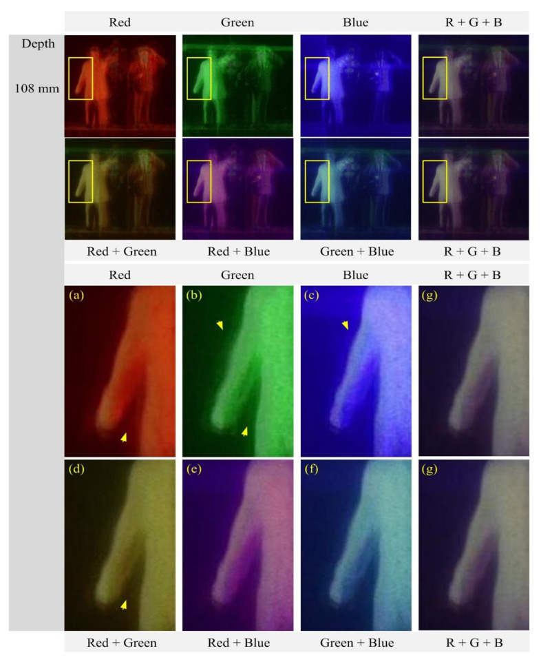
Figure 15 shows the reconstructed images at a depth of 108 mm and their enlarged portions of the areas indicated by the yellow rectangles. As shown in Figure 15a–g, the areas are well focused in all reconstructed images, thus sharp edges are visible in the areas. The selected area of the human object is homogenous, thus it is useful to compare those reconstructed images in terms of smoothness. The image from the red wavelength, as shown in Figure 15a, has a homogenous area with sharp edges. This is useful to extract a homogenous depth map. However, the images from the green and blue wavelengths suffer from impulsive noises. Also, they have shadow areas that are unwanted signals in a depth extraction method. On the other hand, the images from multiple wavelengths have sharper edges than those from single wavelengths, observing the area indicated by arrows. Especially, the image from three wavelengths has a homogenous area with less impulsive noises and shadow areas.
Immersion objectives are similar to water-dipping objectives; however, in this case the sample is under a cover glass. A drop of fluid is then added to the top of the cover glass, and the tip of the objective is brought into contact with the fluid. Often, immersion objectives feature a correction collar to adjust for cover glasses with different thicknesses. Immersion fluids include water, oil (such as MOIL-30), and glycerol.
We won't speak to competitors, but we think our prisms (and prisms in general) are awesome. We have 1x–5x options, including our most recent ...
Spatial periods in pixels vs depth and wavelengths. (a) Parallax image arrays (PIAs) of wavelengths of red (635 nm), green (532 nm), and blue (450 nm). (b) Enlarged views for measuring three spatial periods. (c) Three spatial period graphs according to object depths.
These microscope objectives should be used in applications like traditional and multiphoton microscopy and confocal imaging and are suitable for a variety of imaging modalities, including epi-illumination, oblique illumination, brightfield, and DIC applications. These infinity-corrected objectives have optical elements with an ultra-wide broadband AR coating, designed for use with either 180 mm or 200 mm focal length tube lenses.
Olympusuis2
Additionally, the objective label area may include the objective's specified wavelength range, specialty features or design properties, and more. The exact location and size of each and any of these elements can vary.
The Abbe theory describes image formation as a double process of diffraction [2]. Within this framework, if two features separated by a distance d are to be resolved, at a minimum both the zeroth and first orders of diffraction must be able to pass through the objective's aperture. Since the first order of diffraction appears at the angle: sin(θ1) = λ/d, the minimum object separation, or equivalently the resolution of the objective, is given by d = λ/n*sin(α), where α is the angular semi-aperture of the objective and a factor of n has been inserted to account for the refractive index of the imaging medium. This result overestimates the actual limit by a factor of 2 because both first orders of diffraction are assumed to be accepted by the objective, when in fact only one of the first orders must pass through along with the zeroth order. Dividing the above result by a factor of 2 and using the definition of the numerical aperture (NA = n*sin(α)) gives the famous Abbe resolution limit:
In order to facilitate fast identification, nearly all microscope objectives have a colored ring that circumscribes the body. A breakdown of what magnification each color signifies is given in the table below.
3-D reconstructed images for the PIAs in Figure 9a. Each image of three columns’ left is reconstructed from a single PIA. Each image of four columns’ right is reconstructed from multiple PIAs. The row indicates the depth of each image with a step of 5 mm.
Objects used in our optical experiments and their PIAs and examples of a parallax image of the first-order diffraction in each PIA for (a) three flat objects of ‘S’, ‘M’, and ‘U’ and (b) two human miniatures. See the text for the discussion on the captured PIA.
Example 2: Trinocular MagnificationWhen imaging a sample through trinoculars, the image is magnified by the objective and the eyepieces in the trinoculars. If using a 20X Nikon objective and Nikon trinoculars with 10X eyepieces, then the image at the eyepieces has 20X × 10X = 200X magnification. Note that the image at the eyepieces does not pass through the camera tube, as shown by the drawing to the right.
Figure 11 shows the enlarged images reconstructed at a depth of 110 mm for the object ‘M’ in Figure 10 to compare and evaluate the reconstructed image quality. Three images in Figure 11a–c are reconstructed from the parallax image arrays at three single wavelengths, respectively. Among those images, the image from the red wavelength suffers from blurring whereas the blue wavelength has much less blurring. However, occluding noise arising from the object ‘S’ in the back-projection process exists in the image from the blue wavelength. This problem can increase as the spatial period decreases. Also, it is the same as the wavelength and the number of parallax images. It means that there are advantages and disadvantages according to the wavelength. Four images in Figure 11d–g are reconstructed from multiple-wavelength parallax image arrays. For example, as shown in Figure 11g, the image from three wavelengths suffers from blurring less than those images from the red and green wavelengths. Also, it has fewer occluding noises than the image from the blue wavelength. The background noises in Figure 11g are substantially reduced in the reconstructed image whereas the noises are more visible in the images from single wavelengths, for example, it is seen that the object ‘S’ is visible in the images from single wavelengths. The background noises are related to the number of parallax images, that is, the noises decrease as the number increases. Here, the parallax image number from multiple wavelengths is two or three times larger than the number from a single wavelength. Therefore, the image quality and resolution of the 3-D images of the proposed diffraction grating imaging system with multi-wavelengths are significantly improved, compared to the existing method [20].
Figure 5 shows an example of three parallax images about three wavelengths in our diffraction grating imaging system and graphs of the parallax angles with an increase in distance. The optical configuration used to acquire the parallax image arrays is the same as that used in the previous section. A die of 3-D cube shape was selected as an object to present the effect of the wavelengths on parallax angles. The front face of the die is perpendicular to the optical axis and is located 100 mm away from the grating. The wavelengths λk of the light sources in use are 635 nm (red), 532 nm (green), and 450 nm (blue). The parallax image arrays obtained from red, green, and blue wavelengths and their enlarged views of the parallax images of the first-order diffraction are shown in Figure 5a,b, respectively. As shown in Figure 5b, it is seen that the side of the die is observed as if it is viewed with a parallax angle.
Geometries in diffraction grating imaging among a point object, parallax images (PIs), diffraction grating, an imaging lens, and captured parallax images.
Example 3: Trinocular Magnification (Different Manufacturers)When imaging a sample through trinoculars, the image is magnified by the objective and the eyepieces in the trinoculars. This example will use a 20X Olympus objective and Nikon trinoculars with 10X eyepieces.
Five objective classes are shown in the table to the right; only three common objective classes are defined under the International Organization for Standards ISO 19012-2: Microscopes -- Designation of Microscope Objectives -- Chromatic Correction. Due to the need for better performance, we have added two additional classes that are not defined in the ISO classes.
3-D reconstructed images for the PIAs in Figure 9b. Each image of three columns’ left is reconstructed from a single PIA. Each image of four columns’ right is reconstructed from multiple PIAs. The row indicates the arbitrary depth of each image.
A cover glass, or coverslip, is a small, thin sheet of glass that can be placed on a wet sample to create a flat surface to image across.
Note that Leica, Mitutoyo, Nikon, and Thorlabs use the same tube lens focal length; if combining elements from any of these manufacturers, no conversion is needed. Once the effective objective magnification is calculated, the magnification of the system can be calculated as before.
Secure .gov websites use HTTPS A lock ( Lock Locked padlock icon ) or https:// means you've safely connected to the .gov website. Share sensitive information only on official, secure websites.
For point source separations corresponding to the Rayleigh and Abbe resolution criteria, the combined intensity profile has a local minimum located at the origin between the two maxima. In a sense, this feature is what allows the two point sources to be resolved. That is to say, if the sources' separation is further decreased beyond the Abbe resolution limit, the two individual maxima will merge into one central maximum and resolving the two individual contributions will no longer be possible. The Sparrow criterion posits that the resolution limit is reached when the crossover from a central minimum to a central maximum occurs.
The most common, a standard #1.5 cover glass, is designed to be 0.17 mm thick. Due to variance in the manufacturing process the actual thickness may be different. The correction collar present on select objectives is used to compensate for cover glasses of different thickness by adjusting the relative position of internal optical elements. Note that many objectives do not have a variable cover glass correction, in which case the objectives have no correction collar. For example, an objective could be designed for use with only a #1.5 cover glass. This collar may also be located near the bottom of the objective, instead of the top as shown in the diagram.
The image to the left below shows two Airy disks separated by the Sparrow resolution limit. As described above, the intensity is constant in the region between the two peaks and there is no intensity dip at the origin. In the line cut to the right, the constant intensity near the origin is confirmed.
Using an immersion fluid with a high refractive index allows objectives to achieve numerical apertures greater than 1.0. However, if an immersion objective is used without the fluid present, the image quality will be very low. Objectives following ISO 8578: Microscopes -- Marking of Objectives and Eyepieces will be labeled with an identifier ring to tell the user what immersion fluid the objective is designed to be used with; a list of ring colors can be found in the table above.
Objectives that feature a built-in iris diaphragm are ideal for darkfield microscopy. The iris diaphragm is designed to be partially closed during darkfield microscopy in order to preserve the darkness of the background. This is absolutely necessary for high numerical aperture (above NA = 1.2) oil immersion objectives when using an oil immersion darkfield condenser. For ordinary brightfield observations, the iris diaphragm should be left fully open.
Figure 8 shows an optical experimental setup to evaluate the proposed 3-D imaging system via multiple wavelength diffraction grating imaging. As shown in Figure 8a, the experimental objects were placed 100 mm away from a diffraction grating, and the diffraction grating was located at 300 mm from a camera. The diffraction grating in use is made of two transmissive amplitude diffraction gratings with a line density of 500 lines/mm that are available commercially through perpendicularly concatenating two diffraction gratings in our laboratory. Three types of lasers with an optical power of 4.5 mW and the wavelengths of 635 nm (red), 532 nm (green), and 450 nm (blue) are utilized to illuminate the objects sequentially. Then, parallax images observed through the diffraction grating are acquired by a digital camera with a CMOS sensor of 35.9 × 24 mm and a pixel pitch of 5.95 μm to obtain parallax image arrays. The digital image size of each parallax image array is 3007 × 3007 pixels. Examples of three parallax image arrays corresponding to three types of wavelengths are shown in Figure 8b.
These objectives provide 40X, 60X, or 100X magnification, flat images across the entire visible spectrum, high numerical aperture values, and excellent resolution. The RMS40X-PFO, RMS50X-PFOD, RMS100X-PFO, and RMS100X-POFD are plan fluorite designs, while the RMS100X-O is a plan achromat design. The differences between these designs can be found in the Objective Tutorial tab.
Example 4: Sample AreaThe dimensions of the camera sensor in Thorlabs' previous-generation 1501M-USB Scientific Camera are 8.98 mm × 6.71 mm. If this camera is used with the Nikon objective and trinoculars from Example 1, which have a system magnification of 15X, then the image area is:
This paper describes a computational 3-D imaging system based on diffraction grating imaging with laser sources of multiple wavelengths. It was proven that a diffraction grating imaging system works well as a 3-D imaging system in our previous studies. The diffraction grating imaging system has advantages such as no spherical aberration and a low-cost system, compared with the well-known 3-D imaging systems based on a lens array or a camera array. However, a diffraction grating imaging system still suffers from noises, artifacts, and blurring due to the diffraction nature and illumination of single wavelength lasers. In this paper, we propose a diffraction grating imaging system with multiple wavelengths to overcome these problems. The proposed imaging system can produce multiple volumes through multiple laser illuminators with different wavelengths. Integration of these volumes can reduce noises, artifacts, and blurring in grating imaging since the original signals of 3-D objects inside these volumes are integrated by our computational reconstruction method. To apply the multiple wavelength system to a diffraction grating imaging system efficiently, we analyze the effects on the system parameters such as spatial periods and parallax angles for different wavelengths. A computational 3-D imaging system based on the analysis is proposed to enhance the image quality in diffraction grating imaging. Optical experiments with three-wavelength lasers are conducted to evaluate the proposed system. The results indicate that our diffraction grating imaging system is superior to the existing method.
Dipping objectives are designed to correct for the aberrations introduced by the specimen being submerged in an immersion fluid. The tip of the objective is either dipped or entirely submerged into the fluid.
All objectives featured on this page are compatible with our microscope nosepiece modules for DIY Cerna® systems, which accept RMS, M25 x 0.75, or M32 x 0.75 objective threading.
Uplansapo
Equation (5) says that the parallax angle is proportional to the spatial period. Since the spatial period is proportional to the wavelength, the larger the wavelength of the light source in use, the larger the parallax angle. This means that more 3-D information of an object can be obtained. This fact is well-demonstrated experimentally in Figure 5b. Based on this fact, three graphs of the theoretical parallax angles by the first-order diffraction with change in the object depth are depicted in Figure 5c. According to these graphs, it is seen that a parallax angle decreases slowly as the object moves away from the grating. Particularly noteworthy is the change in the parallax angle according to the wavelength, since the wavelength is an important optical design factor in the design of a diffraction grating imaging system.
Reconstructed images and their zoomed versions for the human object at the depth z = 108 mm. (a) Red (b) Green (c) Blue (d) Red + Green (e) Red + Blue (f) Green + Blue, and (g) Red + Green + Blue wavelength.
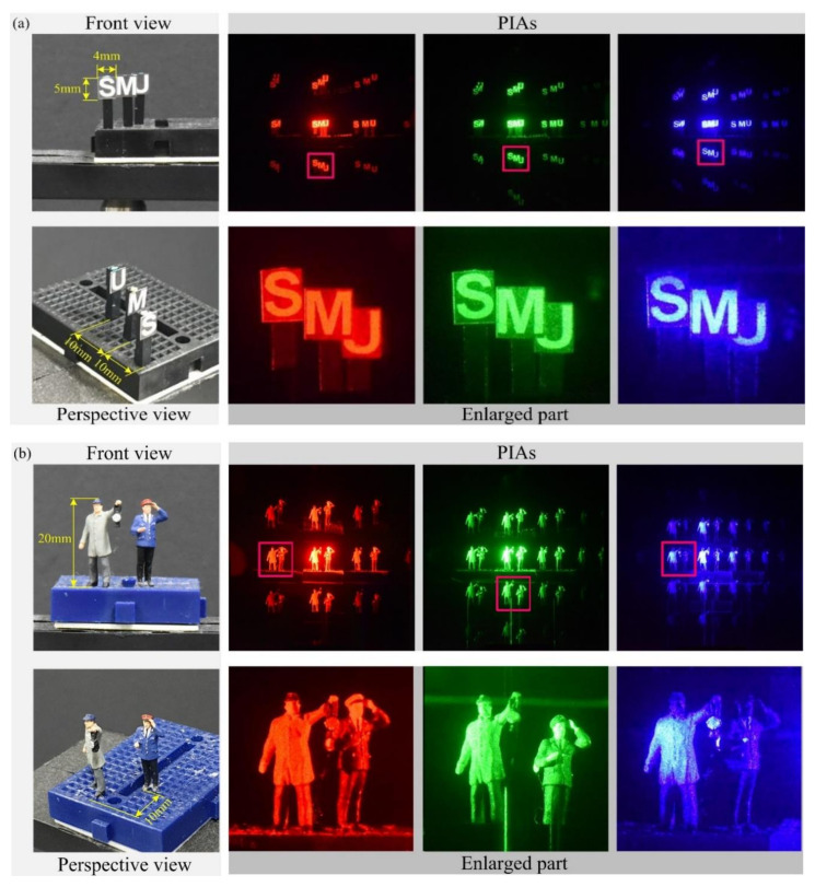
Figure 2 shows basic geometries to explain the ray analysis in diffraction grating imaging, where a point object, its parallax images, and an imaging lens are introduced [20,21,22]. Here, a point object is located at (xO, yO, zO) and a diffraction grating is located at a distance d away from an imaging lens in the x–y plane. The z-coordinates of all parallax images are the same as zO according to diffraction grating imaging. The grating order is limited in the first-order diffraction to understand the system easily without loss of generality. Let the −1st and 1st order parallax images be PI(x−1st, yO, zO) and PI(x1st, yO, zO) which are the ±1st order diffraction of the point object. Here, the point object at (xO, yO, zO) is the 0th order parallax image. The diffraction angle θ between the 1st order and the 0th order parallax images is written as θ = sin−1(mλk/a), where λk is the wavelength of the kth light source, and a is the grating pitch and m is the diffraction order such as 0, 1, or −1. The tangent of the diffraction angle provides the locations of the parallax images. Here are the x-coordinates as follows:
The camera sensor dimensions can be obtained from the manufacturer, while the system magnification is the multiplicative product of the objective magnification and the camera tube magnification (see Example 1). If needed, the objective magnification can be adjusted as shown in Example 3.
where m and n are diffraction orders, and xmth and ynth are the x-position for order m and the y-position for order n, respectively. Here, the 0th virtual pinhole is the imaging lens. Equation (7) says that the position of each virtual pinhole increases in the x and y directions as the depth of the object increases. The virtual images are mapped from the images I(xmth, ynth, zO) in the pickup plane, and their x-coordinate is given by
Also referred to as the parfocal distance, this is the length from the shoulder to the top of the specimen (in the case of objectives that are intended to be used without a cover glass) or the top of the cover glass. When working with multiple objectives in a turret, it is helpful if all of the parfocal distances are identical, so little refocusing will be required when switching between objectives. Thorlabs offers parfocal length extenders for instances in which the parfocal length needs to be increased.
Thorlabs provides the theoretical Rayleigh resolution for all of the imaging objectives offered on our site in their individual product presentations.
Experimental setup for PIA pickup. (a) Configuration of the optical experiment. (b) Examples of PIAs obtained from using lasers of wavelengths of 635 nm (red), 532 nm (green), and 450 nm (blue). See the text for the details on the configuration of optical devices.
Figure 1 shows the proposed diffraction grating system. Our system consists of an optical pickup process and a corresponding computational reconstruction process. Three parallax image arrays are acquired via sequential illumination of lasers with three different wavelengths such as 635, 532, and 450 nm, respectively. Since the depth resolutions of those parallax image arrays are different from each other, a computational reconstruction method has to merge multiple volumes from multiple PIAs into a single volume. To do so, we introduce the analyses of the spatial period of each parallax image array, the depth resolution, and the parallax angle according to each wavelength, which are given as generalized formulas and data tables. Based on the analyses, we propose a 3-D computational reconstruction method where multiple 3-D images from the parallax image arrays are integrated into a 3-D image. To evaluate the proposed method, subjective evaluation is carried out since it is challenging to prepare the 3-D ground truth images for the resulting images from optical experiments in DGI to calculate a reasonable objective measure. Thus, optical experiments with lasers of three different wavelengths are conducted and the results are compared with the existing method subjectively [20].
To clean immersion objectives after use with immersion oils, use a soft optical cleaning tissue such as our MC-5 premium lens tissues.
OlympusVS200 software
An analysis of the diffraction grating imaging system concerning wavelengths is important in the proposed method since our diffraction grating imaging system employs multiple laser light sources with different wavelengths, which is called multiple wavelength diffraction grating imaging in this paper. Equation (2) says that the wavelength of the light source affects the spatial period in diffraction grating imaging. The depth information of an object is determined by the spatial period; thus, the spatial period can be considered as a function of the wavelength and object depth. Since the spatial period is a key parameter in the 3-D computational reconstruction process, it is necessary to calculate the spatial periods for one depth according to multiple wavelengths and it needs to integrate the 3-D images obtained from the parallax image arrays of multiple wavelengths. To solve this problem, an analysis of spatial periods is presented, depending on the wavelengths and depths.
The y-coordinates, ymth are straightforward by replacing xO with yO in Equation (1). Also, the spatial period X, the distance between parallax images PIs, is then rewritten by
Threading allows an objective to be mounted to a nosepiece or turret. Objectives can have a number of different thread pitches; Thorlabs offers a selection of microscope thread adapters to facilitate mounting objectives in different systems.
Objectives are commonly divided by their class. An objective's class creates a shorthand for users to know how the objective is corrected for imaging aberrations. There are two types of aberration corrections that are specified by objective class: field curvature and chromatic aberration.
All of these objectives are suitable for brightfield microscopy, and all but the RMS100X-O are suitable for DIC microscopy. Additionally, the RMS60X-PFOD and RMS100X-PFOD objectives feature a built-in iris diaphragm, which is designed to be partially closed during darkfield microscopy in order to preserve the darkness of the background. This is absolutely necessary for high numerical aperture (above NA = 1.2) oil immersion objectives when using an oil immersion darkfield condenser. For ordinary brightfield observations, the iris diaphragm should be left fully open. The iris diaphragm adjustment is pictured above and to the right.
where m and n are the diffraction orders in the x and y coordinates, respectively, and the z-coordinate zI in the pick-up plane is determined by the Gaussian lens formula.
MitutoyoObjective lens
The shoulder is located at the base of the objective threading and marks the beginning of the exposed objective body when it is fully threaded into a nosepiece or other objective mount.
Figure 4c shows three graphs of space period vs depth for three wavelengths. It is seen that the graphs for the wavelengths are all linear. Here, the slope of each graph means the depth resolution and a constant slope means that the depth resolution is independent of the object depth. This property is an advantage compared to the fact that the depth resolution of a depth extraction system with a normal camera array deteriorates as the object distance increases. Also, it is seen that the slope increases as the wavelength increases, which means that the depth resolution is proportional to the wavelength. This result can be utilized as an important parameter in the design of depth extraction systems using diffraction grating imaging.
An important parameter in many imaging applications is the resolution of the objective. This tutorial describes the different conventions used to define an objective's resolution. Thorlabs provides the theoretical Rayleigh resolution for all of the imaging objectives offered on our site; the other conventions are presented for informational purposes.
Figure 3 shows the geometries to understand the parallax angles for PIs. The real ray emanating from the point object passes through a point G on the diffraction grating. Also, it passes through the imaging lens center after diffraction and reaches the PI pickup plane. The ray arriving at I(x1th, yO, zO) on the PI pickup plane looks as if it comes from the parallax image PI(x1th, yO, zO). However, it emanates from the point object located at (xO, yO, zO). Thus, the diffraction at the point G on the grating enables the imaging lens to view the perspective scene of the point object, where the parallax angle ϕ of the parallax image PI(x1th, yO, zO) can be expressed as the angle formed by the optical axis and the line segment connecting the point G and the point PI(xO, yO, zO). Here, based on triangular symmetry, the point G(xmth, ynth, zO) on the grating is written as
Here, if the resolution ΔX of the spatial period is set to the pixel size of the digital camera in use, the spatial period can be defined in a unit of a pixel number. Accordingly, the depth resolution is determined by Equation (6).
Magnification is not a fundamental value: it is a derived value, calculated by assuming a specific tube lens focal length. Each microscope manufacturer has adopted a different focal length for their tube lens, as shown by the table to the right. Hence, when combining optical elements from different manufacturers, it is necessary to calculate an effective magnification for the objective, which is then used to calculate the magnification of the system.
Reconstructed images for the object ‘M’ at a depth z = 110 mm. (a) Red (b) Green (c) Blue (d) Red + Green (e) Red + Blue (f) Green + Blue, and (g) Red + Green + Blue.
Recently, a diffraction grating imaging (DGI) system has been introduced to acquire and process a 3-D image [18,19,20,21,22]. The optical configuration of a DGI system consists of an amplitude diffraction grating in the form of a transmissive film, a camera, and a laser as a light source [18]. The optical structure of DGI is inexpensive and simple compared with the camera array system. In addition, the grating in use is thinner, lighter, and less expensive than a lens array. Thus, it is easy to concatenate two or more gratings to design a 3-D imaging system [19], Also, it is free from optical aberration that occurs in the lens array. Therefore, the diffraction grating imaging system can be one of the promising techniques in 3-D information processing systems such as 3-D object recognition and depth extraction.
These objectives use standard RMS threading. To use these objectives with a different thread standard, please see our RMS Thread Adapters.
Immersion oils are available with low or very low autofluorescence. Autofluorescence is the natural fluorescence emission of the oil when exposed to light. Each immersion oil has a different level of background emission, which either increases or decreases the contrast of the image; oils with very low autofluorescence are optimized for use in sensitive or UV fluorescence microscopy applications.
This work was supported by Institute for Information & Communications Technology Promotion (IITP) grant funded by the Korea government (MSIP) (No. 2017-0-00515, Development of integraphy content generation technique for N-dimensional barcode application).
Three-dimensional (3-D) imaging plays a key role in 3-D techniques. Also, their application fields are very broad such as augmented reality, autonomous driving, entertainment, defense, and biomedical imaging [1,2,3,4,5,6]. The main components of a 3-D imaging system are divided into 3-D image acquisition, 3-D image processing, and 3-D visualization. Among them, integral imaging was proposed as one of the promising techniques for 3-D applications by Lippman in 1908 [1]. Normally, 3-D integral imaging systems employ a camera array, a lens array, or a moving camera to construct 3-D systems. They can be applied to various applications such as 3-D depth extraction, 3-D display, 3-D visualization, 3-D pattern recognition, 3-D reconstruction, etc. [7,8,9,10,11,12,13,14,15,16,17]. As the first step in integral imaging, 3-D image acquisition is essential in that its optical devices provide image data for 3-D objects as an image array. This image array is one of the effective 3-D image formats in 3-D image processing and visualization.
Geometries for virtual pinhole model among a point object, virtual pinholes (VP), virtual image (VI) plane, and I(x1st, yO,zO). For more details see text.
These Microscope Immersion Oils are designed for use with Oil Immersion Microscope Objectives. Placing an oil medium between the front surface of the objective and the cover glass allows the objective to achieve a high numerical aperture, maximizing light collection by the objective. To minimize refraction of light from the sample, the refractive indices of immersion oils are very close to those of cover glass.
Oct 7, 2015 — A distinctive, discontinued telescope: the Edmund Scientific Astroscan ... I am frequently asked about this beautiful telescope! People think it ...
Objectives following ISO 8578: Microscopes -- Marking of Objectives and Eyepieces will be labeled with an identifier ring to tell the user what immersion fluid the objective is designed to be used with; a list of ring colors can be found in the table to the right.
Example 1: Camera MagnificationWhen imaging a sample with a camera, the image is magnified by the objective and the camera tube. If using a 20X Nikon objective and a 0.75X Nikon camera tube, then the image at the camera has 20X × 0.75X = 15X magnification.
Field curvature (or Petzval curvature) describes the case where an objective's plane of focus is a curved spherical surface. This aberration makes widefield imaging or laser scanning difficult, as the corners of an image will fall out of focus when focusing on the center. If an objective's class begins with "Plan", it will be corrected to have a flat plane of focus.
Figure 13 shows enlarged versions of the reconstructed images of a depth of 100 mm for the human object in Figure 12 to evaluate the image quality. Three images are reconstructed from single wavelengths, as shown in Figure 13a–c. Among these images, the image from the red wavelength suffers from strong blurring whereas the image from the green wavelength is much less blurred than that of the red. However, the image from the green wavelength suffers from the crosstalk, where the green horizontal bar in the image is the crosstalk from another parallax image. These unwanted artifacts exist in the image from the blue wavelength, as indicated by yellow and red arrows in Figure 13. This artifact arises from the interference or overlapping between the parallax images, which is unavoidable due to the nature of diffraction grating imaging. Such crosstalk artifact is more likely to occur as the spatial period is shorter or the illumination is stronger. For example, the image of the red wavelength unlikely occurs in the crosstalk, as shown in Figure 13a, whereas the image of the green wavelength with strong illumination can suffer from the crosstalk severely. On the other hand, in the images from multiple wavelengths, as shown in Figure 13d–g, the crosstalk is suppressed in the reconstructed images from multiple wavelengths. For example, the image from the red and blue wavelength, as shown in Figure 13c shows the best performance in terms of the crosstalk problem. Also, the crosstalk is substantially reduced in the image from three wavelengths. Therefore, the proposed diffraction grating imaging system with multiple wavelengths is more robust against the crosstalk problem than the system with a single wavelength.
Conceptualization, J.-Y.J. and H.Y.; methodology, J.-Y.J. and H.Y.; software, J.-Y.J. and H.Y.; validation, J.-Y.J. and H.Y.; formal analysis, J.-Y.J.; investigation, J.-Y.J. and H.Y.; resources, J.-Y.J.; data curation, J.-Y.J. and H.Y.; writing—original draft preparation, J.-Y.J. and H.Y.; writing—review and editing, H.Y.; visualization, J.-Y.J.; supervision, H.Y.; project administration, H.Y.; funding acquisition, H.Y. All authors have read and agreed to the published version of the manuscript.
A computational reconstruction method is required to produce a 3-D volume from a parallax image array in diffraction grating imaging since a parallax image array of diffraction grating imaging has a different form compared with those of a lens array or camera array. For this purpose, a computational reconstruction method suitable for diffraction grating imaging was proposed in our previous research [15,20]. However, the previous methods were developed for a single wavelength. In this paper, a 3-D volume reconstruction method with multiple wavelength parallax image arrays is proposed to improve the image quality of diffraction grating imaging.
On the other hand, while an object is illuminated with a plane laser of a single wavelength, the plane rays scattered from the surface of the object are observed through a transmission diffraction grating. It is observed that the rays containing surface information of the object are periodically imaged in space. Here, the rays of the object are observed as an image, which is called a parallax image [18,19,20]. In other words, the rays emanating from the surface of the object are diffracted by the grating. The diffracted rays for the object can be imaged in the form of a two-dimensional array and a captured version of those images is called a parallax image array (PIA). In addition, the distance between the periodically observed parallax images is defined as a spatial period [20]. Since the spatial period is proportional to the distance between the object and the diffraction grating, the spatial period is an important parameter providing depth information of a 3-D object. After that, a computational reconstruction algorithm generates a 3-D volume from a parallax image array using the spatial period [20].
The ray coming from the point object at an angle of ϕ is related with the 1st order parallax image at (x1st, yO, zO), as shown in Figure 3. The ray going to the imaging point I(x1st, yO, zO) has the same angle of ϕ. The point I(x1st, yO, zO) is mapped with the parallax image of an angle of ϕ. As shown in Figure 6, let us draw a line passing through the point object and the point G(x1st, yO, zO) on the grating. This line meets the pickup plane. If taking another object point near the current object point, this line highlighted in blue also passes through the same point VI(x1st, yO, 0) on the x-axis. The point on the x-axis is called a virtual pinhole [20], as shown in Figure 6.
Jan 10, 2023 — Hex key sizes ; 6mm (or 7/32 inch) Allen key · Shop for 6mm Allen keys ; 8mm (or 5/16 inch) Allen key · Shop for 8mm Allen keys ; 10mm (or 3/8 inch) ...
To adapt the examples shown here to your own microscope, please use our Magnification and FOV Calculator, which is available for download by clicking on the red button above. Note the calculator is an Excel spreadsheet that uses macros. In order to use the calculator, macros must be enabled. To enable macros, click the "Enable Content" button in the yellow message bar upon opening the file.
The images of a mouse kidney below were all acquired using the same objective and the same camera. However, the camera tubes used were different. Read from left to right, they demonstrate that decreasing the camera tube magnification enlarges the field of view at the expense of the size of the details in the image.
SPHERICAL RADIUS: 200.00mm +/- 1.00mm CONCAVE SURFACE ACCURACY: 1/4 WAVE MAXIMUM AT 0.633um, 2 FACES. SURFACE QUALITY: 20-10 PER MIL-O-13830, 2 FACES. SURFACE ...


 Ms.Cici
 8618319014500