
Magnifying Glass for Cannabis: The Secrets of Trichomes - best magnifier for weed
Diagram ofdiffractionof light
Light passing through a single slit forms a diffraction pattern somewhat different from those formed by double slits or diffraction gratings. Figure 1 shows a single slit diffraction pattern. Note that the central maximum is larger than those on either side, and that the intensity decreases rapidly on either side. In contrast, a diffraction grating produces evenly spaced lines that dim slowly on either side of center.
destructive interference for a single slit: occurs when D sin θ = mλ, (form=1,–1,2,–2,3, . . .), where D is the slit width, λ is the light’s wavelength, θ is the angle relative to the original direction of the light, and m is the order of the minimum
Types ofdiffraction
9. (a) 0.0150º; (b) 0.262 mm; (c) This distance is not easily measured by human eye, but under a microscope or magnifying glass it is quite easily measurable.
Figure 3. A graph of single slit diffraction intensity showing the central maximum to be wider and much more intense than those to the sides. In fact the central maximum is six times higher than shown here.
Diffractionexamples
Helium-Neon laser is a type of gas laser in which a mixture of helium and neon gas is used as a gain medium. Helium-Neon laser is also known as He-Ne laser.
Diffractionof waves
Figure 1. (a) Single slit diffraction pattern. Monochromatic light passing through a single slit has a central maximum and many smaller and dimmer maxima on either side. The central maximum is six times higher than shown. (b) The drawing shows the bright central maximum and dimmer and thinner maxima on either side.
From the given information, and assuming the screen is far away from the slit, we can use the equation D sin θ = mλ first to find D, and again to find the angle for the first minimum θ1.
What isdiffractiongrating
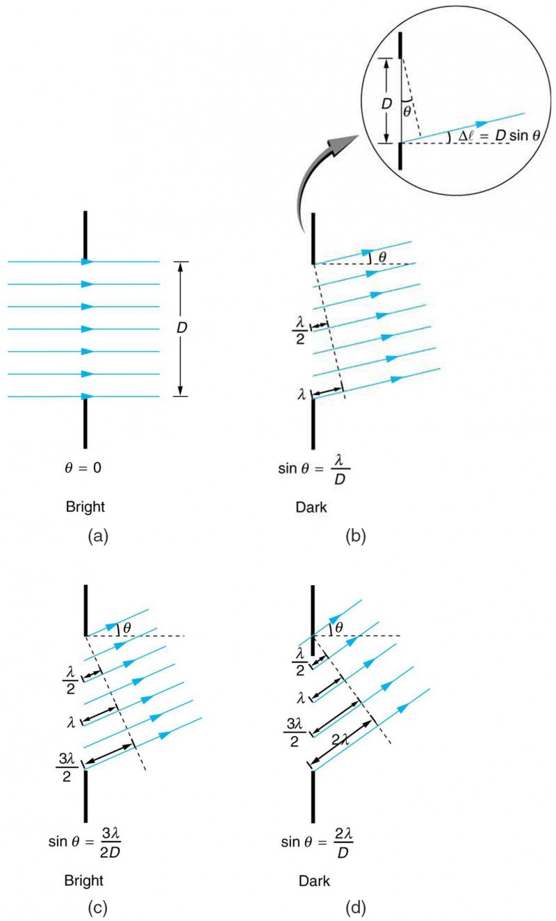
The analysis of single slit diffraction is illustrated in Figure 2. Here we consider light coming from different parts of the same slit. According to Huygens’s principle, every part of the wavefront in the slit emits wavelets. These are like rays that start out in phase and head in all directions. (Each ray is perpendicular to the wavefront of a wavelet.) Assuming the screen is very far away compared with the size of the slit, rays heading toward a common destination are nearly parallel. When they travel straight ahead, as in Figure 2a, they remain in phase, and a central maximum is obtained. However, when rays travel at an angle θ relative to the original direction of the beam, each travels a different distance to a common location, and they can arrive in or out of phase. In Figure 2b, the ray from the bottom travels a distance of one wavelength λ farther than the ray from the top. Thus a ray from the center travels a distance λ/2 farther than the one on the left, arrives out of phase, and interferes destructively. A ray from slightly above the center and one from slightly above the bottom will also cancel one another. In fact, each ray from the slit will have another to interfere destructively, and a minimum in intensity will occur at this angle. There will be another minimum at the same angle to the right of the incident direction of the light.
At the larger angle shown in Figure 2c, the path lengths differ by 3λ/2 for rays from the top and bottom of the slit. One ray travels a distance λ different from the ray from the bottom and arrives in phase, interfering constructively. Two rays, each from slightly above those two, will also add constructively. Most rays from the slit will have another to interfere with constructively, and a maximum in intensity will occur at this angle. However, all rays do not interfere constructively for this situation, and so the maximum is not as intense as the central maximum. Finally, in Figure 2d, the angle shown is large enough to produce a second minimum. As seen in the figure, the difference in path length for rays from either side of the slit is D sin θ, and we see that a destructive minimum is obtained when this distance is an integral multiple of the wavelength.
Fresneldiffraction
[latex]\displaystyle\sin\theta_1=\frac{m\lambda}{D}=\frac{1\left(550\times10^{-9}\text{ m}\right)}{1.56\times10^{-6}\text{ m}}\\[/latex]
In Figure 2 we see that light passing through a single slit is diffracted in all directions and may interfere constructively or destructively, depending on the angle. The difference in path length for rays from either side of the slit is seen to be D sin θ.
Definition ofdiffractionin Physics
Thus, to obtain destructive interference for a single slit, D sin θ = mλ, for m = 1,−1,2,−2,3, . . . (destructive), where D is the slit width, λ is the light’s wavelength, θ is the angle relative to the original direction of the light, and m is the order of the minimum. Figure 3 shows a graph of intensity for single slit interference, and it is apparent that the maxima on either side of the central maximum are much less intense and not as wide. This is consistent with the illustration in Figure 1b.
[latex]\begin{array}{lll}D&=&\frac{m\lambda}{\sin\theta_2}=\frac{2\left(550\text{ nm}\right)}{\sin45.0^{\circ}}\\\text{ }&=&\frac{1100\times10^{-9}}{0.707}\\\text{ }&=&1.56\times10^{-6}\end{array}\\[/latex]
We see that the slit is narrow (it is only a few times greater than the wavelength of light). This is consistent with the fact that light must interact with an object comparable in size to its wavelength in order to exhibit significant wave effects such as this single slit diffraction pattern. We also see that the central maximum extends 20.7º on either side of the original beam, for a width of about 41º. The angle between the first and second minima is only about 24º(45.0º − 20.7º). Thus the second maximum is only about half as wide as the central maximum.
Visible light of wavelength 550 nm falls on a single slit and produces its second diffraction minimum at an angle of 45.0º relative to the incident direction of the light.


 Ms.Cici
 8618319014500