
Magnification - magnification of objective lens
Zinc Selenide Handling and SafetyWhen handling optics, always wear gloves. This is especially true when working with zinc selenide, as it is a hazardous material. For your safety, please follow all proper precautions, including wearing gloves when handling these windows and thoroughly washing your hands afterward. Although ZnSe has a broader transmission range than silicon and germanium, it scratches easily and must be produced synthetically. Click here to download a PDF of the MSDS for ZnSe.
Higher magnification requires higher resolution to realize the full benefit. The higher-powered objectives have correspondingly greater resolving power to take advantage of the increased magnification whereas the lower-power lenses have comparatively less resolution which is ample for their magnification level.
Correction collars are generally used to correct for spherical aberration due to variations in coverslip thickness, temperature, wavelength or for the differing ...
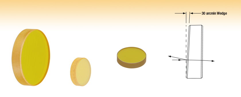
Thorlabs offers these wedged Ø1/2" and Ø1" zinc selenide (ZnSe) windows. These wedged optics eliminate fringe patterns and can be used to help avoid cavity feedback. Windows are useful for protecting a laser output from environmental effects and for beam sampling applications. We also supply planar windows with a variety of substrate materials and coating options. These ZnSe windows are available either uncoated (600 nm - 16 µm) or with a broadband AR coating deposited on both surfaces. The -D AR coating is specified for 1.65 - 3.0 µm (Ravg < 1.0% per surface) while the -E3 AR coating is specified for 7 - 12 µm (Ravg < 1.0% per surface).
LIDT in energy density vs. pulse length and spot size. For short pulses, energy density becomes a constant with spot size. This graph was obtained from [1].
The pulse length must now be compensated for. The longer the pulse duration, the more energy the optic can handle. For pulse widths between 1 - 100 ns, an approximation is as follows:
In order to illustrate the process of determining whether a given laser system will damage an optic, a number of example calculations of laser induced damage threshold are given below. For assistance with performing similar calculations, we provide a spreadsheet calculator that can be downloaded by clicking the button to the right. To use the calculator, enter the specified LIDT value of the optic under consideration and the relevant parameters of your laser system in the green boxes. The spreadsheet will then calculate a linear power density for CW and pulsed systems, as well as an energy density value for pulsed systems. These values are used to calculate adjusted, scaled LIDT values for the optics based on accepted scaling laws. This calculator assumes a Gaussian beam profile, so a correction factor must be introduced for other beam shapes (uniform, etc.). The LIDT scaling laws are determined from empirical relationships; their accuracy is not guaranteed. Remember that absorption by optics or coatings can significantly reduce LIDT in some spectral regions. These LIDT values are not valid for ultrashort pulses less than one nanosecond in duration.
While this rule of thumb provides a general trend, it is not a quantitative analysis of LIDT vs wavelength. In CW applications, for instance, damage scales more strongly with absorption in the coating and substrate, which does not necessarily scale well with wavelength. While the above procedure provides a good rule of thumb for LIDT values, please contact Tech Support if your wavelength is different from the specified LIDT wavelength. If your power density is less than the adjusted LIDT of the optic, then the optic should work for your application.
The specifications to the right are measured data for Thorlabs' ZnSe windows. Damage threshold specifications are constant for ZnSe windows with the same coating, regardless of the size of the window.
[1] R. M. Wood, Optics and Laser Tech. 29, 517 (1998).[2] Roger M. Wood, Laser-Induced Damage of Optical Materials (Institute of Physics Publishing, Philadelphia, PA, 2003).[3] C. W. Carr et al., Phys. Rev. Lett. 91, 127402 (2003).[4] N. Bloembergen, Appl. Opt. 12, 661 (1973).
Znse windowfor sale
Pulsed Microsecond Laser ExampleConsider a laser system that produces 1 µs pulses, each containing 150 µJ of energy at a repetition rate of 50 kHz, resulting in a relatively high duty cycle of 5%. This system falls somewhere between the regimes of CW and pulsed laser induced damage, and could potentially damage an optic by mechanisms associated with either regime. As a result, both CW and pulsed LIDT values must be compared to the properties of the laser system to ensure safe operation.
You may use these html tags and attributes:
An AC127-030-C achromatic doublet lens has a specified CW LIDT of 350 W/cm, as tested at 1550 nm. CW damage threshold values typically scale directly with the wavelength of the laser source, so this yields an adjusted LIDT value:
In addition to the zinc selenide wedged windows offered here, Thorlabs also offers wedged windows with other substrate materials (see the selection guide to the right). Wedged Laser Windows with AR coatings centered around common lasing wavelengths and wedged Beam Samplers with broadband AR coatings on only one face are also available. Additionally, wedged windows with our standard AR coatings or custom sizes and thicknesses are available; please contact Tech Support for more information.
Certain instruments are designed to accommodate additional high-power 60x or 100x objective lenses when extremely high magnification and resolution are critical, such as for cytology or microbiology applications.
According to the test, the damage threshold of the mirror was 2.00 J/cm2 (532 nm, 10 ns pulse, 10 Hz, Ø0.803 mm). Please keep in mind that these tests are performed on clean optics, as dirt and contamination can significantly lower the damage threshold of a component. While the test results are only representative of one coating run, Thorlabs specifies damage threshold values that account for coating variances.
Some microscopes include extra low power 1x or 2x objectives for an even wider field of view to help orient the largest samples. These have become more common on inverted microscopes.
The 10x or 20x medium power objective delivers comfortable viewing magnification and reasonably high resolution to see some finer details in the context of the larger specimen structure. It is commonly used for routine examination, counting cells, measuring proportions, and making sketches.
Pulsed Nanosecond Laser Example: Scaling for Different Pulse DurationsSuppose that a pulsed Nd:YAG laser system is frequency tripled to produce a 10 Hz output, consisting of 2 ns output pulses at 355 nm, each with 1 J of energy, in a Gaussian beam with a 1.9 cm beam diameter (1/e2). The average energy density of each pulse is found by dividing the pulse energy by the beam area:
Thorlabs will accept all ZnSe windows back for proper disposal. Please contact Tech Support to make arrangements for this service.
Beam diameter is also important to know when comparing damage thresholds. While the LIDT, when expressed in units of J/cm², scales independently of spot size; large beam sizes are more likely to illuminate a larger number of defects which can lead to greater variances in the LIDT [4]. For data presented here, a <1 mm beam size was used to measure the LIDT. For beams sizes greater than 5 mm, the LIDT (J/cm2) will not scale independently of beam diameter due to the larger size beam exposing more defects.
These uncoated Infrared Plano-Convex lenses are constructed with materials that are well-matched for IR applications, especially focusing.
PART. FUNCTION. 1. Ocular lens/ eyepiece. -magnifies 10x. 2. Body tube/ocular tube. -keeps proper distance between eyepiece and objective lenses.
ZnSemirror
However, the maximum power density of a Gaussian beam is about twice the maximum power density of a uniform beam, as shown in the graph to the right. Therefore, a more accurate determination of the maximum linear power density of the system is 1 W/cm.
Practically, low magnification facilitates efficient scanning of the overall specimen to find areas of interest to study further, saving significant time compared to searching blindly at high power. It provides necessary contextual orientation.
The set of 3 objective lenses on most compound microscopes elegantly fulfills the range of observational needs in microscopy, from scanning the big picture to examining the most minute details. Their differing optical properties and fields of view provide efficient and flexible viewing capabilities not possible with a single objective lens. The specific numbers and powers may be tailored for particular applications, but the core triad arrangement remains ubiquitous out of logical necessity.
Please note that we have a buffer built in between the specified damage thresholds online and the tests which we have done, which accommodates variation between batches. Upon request, we can provide individual test information and a testing certificate. The damage analysis will be carried out on a similar optic (customer's optic will not be damaged). Testing may result in additional costs or lead times. Contact Tech Support for more information.
The multiple objectives with parcentered optics allow users to quickly switch between lenses and magnifications to obtain just the right view. This facilitates efficient and intuitive workflows.
The adjusted LIDT value of 350 W/cm x (1319 nm / 1550 nm) = 298 W/cm is significantly higher than the calculated maximum linear power density of the laser system, so it would be safe to use this doublet lens for this application.
For other uses, see Laser (disambiguation). "Laser beam" redirects here. Not to be confused with LazarBeam or Lazer Beam. A laser is a device that emits ...
Lenses with lower power and larger fields of view can have optics optimized for brightness whereas high magnification lenses with narrow fields are optimized for resolution at the expense of brightness.
Proper illumination from below is vital for viewing clarity. The maximum resolution or resolving power is limited by the wavelength of light and optics. Higher quality objectives provide greater usable resolution to see fine details.
Pulsed lasers with high pulse repetition frequencies (PRF) may behave similarly to CW beams. Unfortunately, this is highly dependent on factors such as absorption and thermal diffusivity, so there is no reliable method for determining when a high PRF laser will damage an optic due to thermal effects. For beams with a high PRF both the average and peak powers must be compared to the equivalent CW power. Additionally, for highly transparent materials, there is little to no drop in the LIDT with increasing PRF.
ZnSerefractive index
The energy density of the beam can be compared to the LIDT values of 1 J/cm2 and 3.5 J/cm2 for a BB1-E01 broadband dielectric mirror and an NB1-K08 Nd:YAG laser line mirror, respectively. Both of these LIDT values, while measured at 355 nm, were determined with a 10 ns pulsed laser at 10 Hz. Therefore, an adjustment must be applied for the shorter pulse duration of the system under consideration. As described on the previous tab, LIDT values in the nanosecond pulse regime scale with the square root of the laser pulse duration:
When pulse lengths are between 1 ns and 1 µs, laser-induced damage can occur either because of absorption or a dielectric breakdown (therefore, a user must check both CW and pulsed LIDT). Absorption is either due to an intrinsic property of the optic or due to surface irregularities; thus LIDT values are only valid for optics meeting or exceeding the surface quality specifications given by a manufacturer. While many optics can handle high power CW lasers, cemented (e.g., achromatic doublets) or highly absorptive (e.g., ND filters) optics tend to have lower CW damage thresholds. These lower thresholds are due to absorption or scattering in the cement or metal coating.
Thorlabs expresses LIDT for CW lasers as a linear power density measured in W/cm. In this regime, the LIDT given as a linear power density can be applied to any beam diameter; one does not need to compute an adjusted LIDT to adjust for changes in spot size, as demonstrated by the graph to the right. Average linear power density can be calculated using the equation below.
ZnSe windowtransmission
As previously stated, pulsed lasers typically induce a different type of damage to the optic than CW lasers. Pulsed lasers often do not heat the optic enough to damage it; instead, pulsed lasers produce strong electric fields capable of inducing dielectric breakdown in the material. Unfortunately, it can be very difficult to compare the LIDT specification of an optic to your laser. There are multiple regimes in which a pulsed laser can damage an optic and this is based on the laser's pulse length. The highlighted columns in the table below outline the relevant pulse lengths for our specified LIDT values.
A question commonly asked about compound microscopes is: What’s the purpose of having 3 objective lenses attached to it? The answer is quite simple.
High-performance objectives may have adjustable correction collars to optimize the optical correction for viewing specimen slides with different coverslip thicknesses, allowing the best possible image.
When an optic is damaged by a continuous wave (CW) laser, it is usually due to the melting of the surface as a result of absorbing the laser's energy or damage to the optical coating (antireflection) [1]. Pulsed lasers with pulse lengths longer than 1 µs can be treated as CW lasers for LIDT discussions.
The range of magnifications enables users to choose the appropriate level for their particular application, whether surveying tissue architecture or examining subcellular organelles. No single objective lens can provide optimal performance across this wide range of viewing needs.
Shop olympus microscope stereo online with free shipping and fast delivery. This is a very useful and practical tool for your inspection and maintenance.
Phase contrast and fluorescence microscopy require specialized objectives with matched condenser optics to image transparent specimens. These are often incorporated as a fourth objective or replace one of the standard ones.
Germaniumwindow
Having a continuum of magnifications allows the microscope to accommodate samples of vastly different sizes from whole insect bodies down to single cells. A single high-power objective cannot cover this entire range.
The compound light microscope is an indispensable tool used ubiquitously in science disciplines to visualize small objects in fine detail. Unlike simple magnifying glasses, the compound microscope uses two lens systems to enlarge specimens up to 1000x their actual size.
Use this formula to calculate the Adjusted LIDT for an optic based on your pulse length. If your maximum energy density is less than this adjusted LIDT maximum energy density, then the optic should be suitable for your application. Keep in mind that this calculation is only used for pulses between 10-9 s and 10-7 s. For pulses between 10-7 s and 10-4 s, the CW LIDT must also be checked before deeming the optic appropriate for your application.
LIDT in linear power density vs. pulse length and spot size. For long pulses to CW, linear power density becomes a constant with spot size. This graph was obtained from [1].
LargeZnSe window
This scaling gives adjusted LIDT values of 0.08 J/cm2 for the reflective filter and 14 J/cm2 for the absorptive filter. In this case, the absorptive filter is the best choice in order to avoid optical damage.
Now compare the maximum power density to that which is specified as the LIDT for the optic. If the optic was tested at a wavelength other than your operating wavelength, the damage threshold must be scaled appropriately. A good rule of thumb is that the damage threshold has a linear relationship with wavelength such that as you move to shorter wavelengths, the damage threshold decreases (i.e., a LIDT of 10 W/cm at 1310 nm scales to 5 W/cm at 655 nm):
The following is a general overview of how laser induced damage thresholds are measured and how the values may be utilized in determining the appropriateness of an optic for a given application. When choosing optics, it is important to understand the Laser Induced Damage Threshold (LIDT) of the optics being used. The LIDT for an optic greatly depends on the type of laser you are using. Continuous wave (CW) lasers typically cause damage from thermal effects (absorption either in the coating or in the substrate). Pulsed lasers, on the other hand, often strip electrons from the lattice structure of an optic before causing thermal damage. Note that the guideline presented here assumes room temperature operation and optics in new condition (i.e., within scratch-dig spec, surface free of contamination, etc.). Because dust or other particles on the surface of an optic can cause damage at lower thresholds, we recommend keeping surfaces clean and free of debris. For more information on cleaning optics, please see our Optics Cleaning tutorial.
GenICam is a standard of the European Machine Vision Association (EMVA). The GenICam module provides access to GigE compliant cameras. The module will connect ...
The 40x or 100x high power objective produces the highest magnification and resolution to reveal subcellular structures and other intricate details not discernable with the lower powered lenses but has an extremely narrow field of view. It is used for critical inspection of key areas after initial surveys with lower-powered objectives.
Due to its wide transmission band and low absorption in the red portion of the visible spectrum, Zinc Selenide (ZnSe) is commonly used in optical systems that combine CO2 lasers, operating at 10.6 µm, with inexpensive HeNe alignment lasers. Zinc selenide is transparent from 600 nm - 16 µm and is ideal for IR applications. It is also commonly used in thermal imaging systems. ZnSe also transmits some visible light, unlike germanium and silicon, thereby allowing for visual optical alignment. ZnSe has an index of refraction of 2.4 at 10.6 µm.
Find many great new & used options and get the best deals for TELEDYNE FLIR (POINT GREY) CMLN-13S2C-CS, 1.3 MP, 18 FPS, COLOR, CS-MOUNT at the best online ...
The provision of 3 objective lenses with differing optical properties confers important complementary advantages that enhance the microscopy user experience and workflow efficiency.
This adjustment factor results in LIDT values of 0.45 J/cm2 for the BB1-E01 broadband mirror and 1.6 J/cm2 for the Nd:YAG laser line mirror, which are to be compared with the 0.7 J/cm2 maximum energy density of the beam. While the broadband mirror would likely be damaged by the laser, the more specialized laser line mirror is appropriate for use with this system.
Whether your robot is doing vision tracking or you want to brighten up a demo robot, this green LED ring is a powerful tool. This ring emits a green light which ...
The calculation above assumes a uniform beam intensity profile. You must now consider hotspots in the beam or other non-uniform intensity profiles and roughly calculate a maximum power density. For reference, a Gaussian beam typically has a maximum power density that is twice that of the uniform beam (see lower right).
Please note that we have a buffer built in between the specified damage thresholds online and the tests which we have done, which accommodates variation between batches. Upon request, we can provide individual test information and a testing certificate. Contact Tech Support for more information.
As described above, the maximum energy density of a Gaussian beam is about twice the average energy density. So, the maximum energy density of this beam is ~0.7 J/cm2.
ZnSelens
While the basic 3 objective arrangement still dominates today, some microscopes incorporate additional objectives or special enhancements for increased performance and capabilities.
Pulses shorter than 10-9 s cannot be compared to our specified LIDT values with much reliability. In this ultra-short-pulse regime various mechanics, such as multiphoton-avalanche ionization, take over as the predominate damage mechanism [2]. In contrast, pulses between 10-7 s and 10-4 s may cause damage to an optic either because of dielectric breakdown or thermal effects. This means that both CW and pulsed damage thresholds must be compared to the laser beam to determine whether the optic is suitable for your application.
The energy density of your beam should be calculated in terms of J/cm2. The graph to the right shows why expressing the LIDT as an energy density provides the best metric for short pulse sources. In this regime, the LIDT given as an energy density can be applied to any beam diameter; one does not need to compute an adjusted LIDT to adjust for changes in spot size. This calculation assumes a uniform beam intensity profile. You must now adjust this energy density to account for hotspots or other nonuniform intensity profiles and roughly calculate a maximum energy density. For reference a Gaussian beam typically has a maximum energy density that is twice that of the 1/e2 beam.
If this relatively long-pulse laser emits a Gaussian 12.7 mm diameter beam (1/e2) at 980 nm, then the resulting output has a linear power density of 5.9 W/cm and an energy density of 1.2 x 10⁻⁴ J/cm2 per pulse. This can be compared to the LIDT values for a WPQ10E-980 polymer zero-order quarter-wave plate, which are 5 W/cm for CW radiation at 810 nm and 5 J/cm2 for a 10 ns pulse at 810 nm. As before, the CW LIDT of the optic scales linearly with the laser wavelength, resulting in an adjusted CW value of 6 W/cm at 980 nm. On the other hand, the pulsed LIDT scales with the square root of the laser wavelength and the square root of the pulse duration, resulting in an adjusted value of 55 J/cm2 for a 1 µs pulse at 980 nm. The pulsed LIDT of the optic is significantly greater than the energy density of the laser pulse, so individual pulses will not damage the wave plate. However, the large average linear power density of the laser system may cause thermal damage to the optic, much like a high-power CW beam.
The lowest magnification objective is typically a 4x or 10x lens. Its primary purpose is to provide a wide field of view of the overall specimen on the slide for initial orientation and scanning. The low magnification reduces aberrations from optical imperfections.
The major components of a compound microscope are the ocular lens in the eyepiece, the objective turret housing multiple objective lenses, the condenser lens below the stage, the illumination system, and the mechanical arm. Each part plays a critical optical or functional role.
The standard compound light microscope has 3 objective lenses to provide different magnification powers, resolving abilities, and fields of view to visualize specimens in increasing detail.
Pulsed Nanosecond Laser Example: Scaling for Different WavelengthsSuppose that a pulsed laser system emits 10 ns pulses at 2.5 Hz, each with 100 mJ of energy at 1064 nm in a 16 mm diameter beam (1/e2) that must be attenuated with a neutral density filter. For a Gaussian output, these specifications result in a maximum energy density of 0.1 J/cm2. The damage threshold of an NDUV10A Ø25 mm, OD 1.0, reflective neutral density filter is 0.05 J/cm2 for 10 ns pulses at 355 nm, while the damage threshold of the similar NE10A absorptive filter is 10 J/cm2 for 10 ns pulses at 532 nm. As described on the previous tab, the LIDT value of an optic scales with the square root of the wavelength in the nanosecond pulse regime:
The standard compound microscope contains 3 objective lenses with different powers, resolutions, and fields of view to provide a tiered viewing experience.
Znse windowprice
CW Laser ExampleSuppose that a CW laser system at 1319 nm produces a 0.5 W Gaussian beam that has a 1/e2 diameter of 10 mm. A naive calculation of the average linear power density of this beam would yield a value of 0.5 W/cm, given by the total power divided by the beam diameter:
A quality front-coated bounce mirror complete with an attachment bracket is suitable for bouncing laser beams in different directions.
The level of microscope magnification depends on the optical properties of both the ocular and objective lenses. The ocular lens magnifies the primary image 10x. The objectives provide progressively higher magnifying power of 4x, 10x, 40x, and sometimes 100x.
There are different laser technologies. Each technology has its own gain medium and architecture that determine its optical properties.
Now compare the maximum energy density to that which is specified as the LIDT for the optic. If the optic was tested at a wavelength other than your operating wavelength, the damage threshold must be scaled appropriately [3]. A good rule of thumb is that the damage threshold has an inverse square root relationship with wavelength such that as you move to shorter wavelengths, the damage threshold decreases (i.e., a LIDT of 1 J/cm2 at 1064 nm scales to 0.7 J/cm2 at 532 nm):
Thorlabs' LIDT testing is done in compliance with ISO/DIS 11254 and ISO 21254 specifications.First, a low-power/energy beam is directed to the optic under test. The optic is exposed in 10 locations to this laser beam for 30 seconds (CW) or for a number of pulses (pulse repetition frequency specified). After exposure, the optic is examined by a microscope (~100X magnification) for any visible damage. The number of locations that are damaged at a particular power/energy level is recorded. Next, the power/energy is either increased or decreased and the optic is exposed at 10 new locations. This process is repeated until damage is observed. The damage threshold is then assigned to be the highest power/energy that the optic can withstand without causing damage. A histogram such as that below represents the testing of one BB1-E02 mirror.


 Ms.Cici
 8618319014500