
Line Of Sight (3D Analyst) - direct line of sight
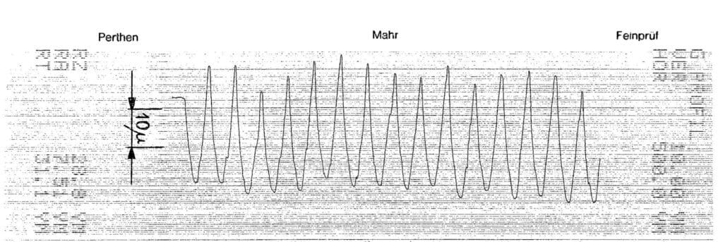
Mean roughness value Ra (DIN 4768) is the arithmetic mean from all values of the roughness profile R within the measuring distance lm. It, therefore, specifies the average deviation of this surface profile from the mean line.
Modulationtransfer functionwiki
While ISO standard is applicable to MTF of the IOL, another way of understanding the image quality transferred by an IOL is the measurement of Strehl Ratio. The Strehl Ratio (SR), is a measure of the overall imaging quality of the tested design compared with that of the perfect diffraction-limited design. Thus the Strehl Ratio can be measured by dividing the intensity of the real or measured IOL point spread function by the intensity of the diffraction limited ideal point spread function.
Mean roughness depth Rz (DIN 4768) is the average value from the individual roughness depths of five individuals measuring distances in sequence. In other words, the calculation is from five Rt values. The deviation from the mean line, specifically focusing on the highest peak and valley.
Most multifocal IOL companies quote their diffractive efficiency in terms of MTF values at a fixed aperture and at a given wavelength of light. They usually experiment with a longer wavelength wave light ( between 500 nm to 550 nm). MTF scores will not only be determined by the spatial frequency, but also the aperture size and the wavelength of light being experimented with. Longer wavelength of mono chromatic light will have lower MTF values compared to shorter (say blue ) wavelength mono chromatic light (Fig 7). This is because diffraction in itself is limiting on contrast. Since diffraction is more with longer wavelength (diffraction involves some light loss due to destructive interference) of light, MTF is poorer with longer wavelength of light than with shorter wavelength of light.
To emphasize, the surface roughness is defined by the minute variations in height of the surface of a given material or workpiece. The individual variances of the peaks and valleys average (Ra value), or quantified by the largest difference from peak-to-valley (Rz). Roughness is usually expressed in microns. A surface that exhibits a Ra of 8 consists of the highest peak and valleys that average no more than 8 µm over a given distance. Roughness may be also measured by comparing the surface of the workpiece to a known sample.
Modulationtransfer functionmatlab
ISO standard requirements for all IOLs is an MTF value of 0.43 at a spatial frequency of 100 lines/mm using an aperture of 3.0 mm in diameter. The 3.0 mm aperture mimics the average of human pupil in diurnal vision. For non aspheric IOLs, or IOLs of other design (say meniscus) which significantly limits the attainment of this value, in no case should the MTF value at 100 lines/mm be less than 0.28.
A question may arise here that if shorter wavelength of light provides higher MTF values, why do ophthalmic companies experiment with longer wavelength of light, usually beyond 500 nm? Theoretically, though 405 nm wavelength of light (Violet) should give you higher MTF values, yet optical designs with diffraction gratings (steps or rings) are limited by their capabilities to provide resolution or contrast at that wavelength of light. You see, the diffractive steps designed in the multifocal IOL of any company, can diffract light with maximum efficiency with longer wavelength of light while shorter wavelength of light will pass through the steps or rings less diffracted. The shorter the wavelength of light, less it bends by diffraction. This will actually limit the MTF values of the near and intermediate though MTF of distance image will be higher as the distance MTF will be still obtained due to the refraction of light by the base curvature of the lens.
-------------------------------------------------------------------------------------------------------------------------------
Modulationtransfer functionformula
The Contrast or modulation ratio is the difference between the brightest part and the darkest part of an image. This difference is quantified as a ratio and hence the term contrast ratio. In the spatial frequency described above and in Figure 1, we have alternate white and dark lines. We can measure the amount of light coming from each white and dark lines. The contrast/modulation ratio is arrived by simply averaging the difference in maximum and minimum light intensities. Thus contrast/ modulation ratio is described by the equation :
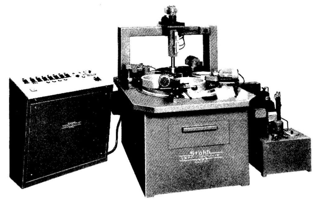
Surface roughness and surface flatness are two quite different concepts and are important to remember. Many of the electronic measuring instruments in use today for determining surface finish quality has microprocessor control systems and printers (Figure 54). However, the true value of the results obtained is open to dispute; as most are only approximate, and vary according to the device concerned. To emphasize, it is essential to compare the type of probe (radius), needle pressure, measuring distance, and filtering (cut-off), see DIN Standard 4768.
Mtf transfer functionppt
With a given grit size and fluid viscosity, varying the lapping pressure produces a higher or lower material removal rate, a thicker or thinner film, and a rougher or finer surface finish. In practice, therefore, the pressure is usually light at the beginning of the process, increasing as work proceeds, and diminished towards the end. This results in the optimum material removal rate, surface finish, and flatness achieving overall surface finish quality to perfection. The waviness (also known as peaks and valleys) is a calculation of surface irregularities with a spacing greater than the surface roughness. These usually occur due to warping, vibrations, or deflection during the machining process.
By definition the MTF is a measure of the ability of lens to transfer contrast at a particular resolution from the object to the image. It is therefore the ability of the lens to transfer the details of the object to the image. Thus it is a ratio of image contrast to object contrast.
Maximum peak to valley height Rt (DIN 4748) is the vertical distance between the highest peak and lowest peak of the roughness profile R within the overall measuring distance lm. In other words, this is the height difference between the highest mountain and lowest valley within the measured range.
1. EN/ISO 11979-2: Ophthalmic Implants Intraocular Lenses d Part 2: Optical Properties and Test Methods, Geneva, International Organization for Standardization, 1999
Modulationtransfer functionimage processing
The Modulation Transfer Function (MTF) is defined as the modulation (Mi) of the image divided by the modulation (Mo) of the object :
Remember this is exactly the minimum angle of resolution required for seeing each limb of the letter E of the Snellen Visual Acuity chart. Hence, 30cpd (100 lines/mm) is equivalent to reading 6/6 or 20/20 of the Snellen Chart.
4. MTF Curves and Lens Performance, Section 2.6 of the Imaging Resource Guide. Edmund Optics (https://www.edmundoptics.in/knowledge-center/application-notes/imaging/mtf-curves-and-lens-performance/)
To explain this more, resolution and contrast are closely related. Resolution is determined by Airy Disc pattern ( explained in the article Understanding the Point Source Function and Strehl Ratio of a lens system https://www.quickguide.org/post/points-spread-function ). Airy disk is calculated by the following equation
The number of lines or bars per millimeter determines spatial frequency, that is, the spacing of lines per unit interval. This interval could be expressed in lines per millimeter (lp/mm) or degrees per cycle of vison (cpd), where each degree of vision has 60 minutes. High spatial frequency refers to higher lines per millimeter or higher cycles per degree of vision. High spatial frequency is therefore accompanied by higher degradation of the quality of image transferred by the lens.
Ideally in terms of percentage the MTF of a lens should be 100 % or the value of the MTF ratio should be 1. However, most lenses, including the human eye, are not a perfect optical system. As a result, when rays of light from an object pass through them, they undergo certain degree of degradation. Therefore, what researchers are interested in. is to understand how far is the degradation of image noticed when compared to the object resolution.
Fig 6 explains the MTF values of Alcon Vivity lens when compared to the AcrySof IQ for a 20.0 diopter lens in a model eye with 50 lines/mm at 3 mm aperture. The Y axis shows the MTF plotted while the X axis represents the positive and negative powered lenses dialed causing drop in modulation of targets and subsequently plotted.
While defocus curves generated by real world implantation of the EDOF or multifocal IOL gives us an idea of the lens ability to provide a range of functional vision, the Modulation Transfer Function (MTF) gives an understanding of the optical quality provided by the lens in a laboratory set up.
Reach out to our worldwide readership base to advertise your products and services related to eyecare. To enquire, subscribe and drop a message.
In Fig 4 you can notice a very poor contrast or modulation as the difference between light transmitted by the white and black bars or lines are minimum.
Therefore, the modulation transfer function plot describes the modulation of the lens as the object increases or decreases in complexity. The X axis represents the number of lines per millimeter (spatial frequency) while the Y axis represents the modulation score. As spatial frequency or lines per millimeter increases the MTF value decreases as a thumb rule for any lens.
Fig 2 The Imax is the maximum intensity that we get from the white lines and Imin is the minimum intensity that we get from the dark or black lines. The original output refers to the object contrast which is theoretically 1 in the equation. The output signal refers to the image contrast.
Modulationtransfer functionRadiology
The Resolution is the ability of the lens to distinguish minute details. With humans, our ability to distinguish two sperate objects as distinctly separate objects, is met only when the rays of light from the two objects subtend at an angle of 1 min of arc at the nodal point of eye ( refer to the article Decoding Snellen Chart in 4 mins https://www.quickguide.org/post/decoding-snellen-s-chart-in-4-mins ). In terms of MTF and in a laboratory set up, this is described as the ability to distinguish the highest number of lines per millimeter. Thought MTF is the measure of the contrast that the optics of the lens system offer, yet resolution and contrast are closely linked. You cannot have great MTF values with a lens system that offers great contrast but poor resolution (refer to my article 'Understanding the Point Source Function and Strehl Ratio of a lens system' https://www.quickguide.org/post/points-spread-function ).
The porosity of the microstructure must be taken into account in the case ofoxide ceramic and sintered metals. Frequently so, bearing ratios are measured at different levels of the surface roughness and specified in %. Visual inspection performing by means of a comparison between a polished surface and an unpolished surface. Seeing the surface texture between the two in the below images.
Mtf transfer functionin optics
3. Imaging quality of intraocular lenses; Rainer Rawer, Wilhelm Stork, Christoph W. Spraul, Christian Lingenfelder; J CATARACT REFRACTIVE SURG - VOL 31, AUGUST 2005
Figure 57: Shows a matte-lapped aluminum part at a magnification of 1600 and with the corresponding measurement diagram.
With zero defocus, the AcrySof IQ ( SN60WF) shows better MTF values. However, with a defocus between -1.0 and -2.0 diopter lenses (corresponding to a distance of 100 cm and 50 cm respectively from eye), the Vivity ( DFT015 ) shows better MTF values signifying its extended range of vision capability.
Mtf transfer functionin lens
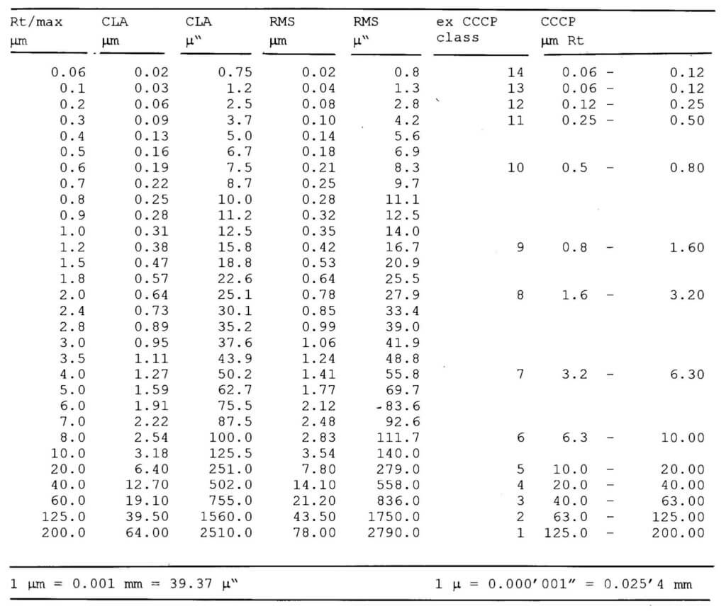
The international surface finish standards (DIN 4762, 4768, ISO 4287/1-2. 4288) are applied in an analogous manner, in that the surface finish quality is specified in Ra values or in the even more accurate Rt values. In practice, the more realistic value Rz is also specified, which is determined by averaging 5 separately measured Rt values. Suitable measuring equipment for acquiring these values are now commercially available (Figure 54).
Is the MTF on-axis or off-axis. Manufacturers most often quote MTF for on-axis but are silent about MTF off-axis, that is how the lens performs with small amounts of decentration (in eye we know there are natural decentrations too).
where NA stands for numerical aperture. Smaller Airy Disk leads to higher resolution. With a shorter wavelength of light the Airy Disk will be smaller per the equation that would lead to a higher resolution or intensity of light.
For measurement of the MTF a standard set up is created. The light source or laser is usually monochromatic light of around 550 nm approximately as it represents peak human photopic sensitivity. A pin hole is placed to minimize diffraction at the light source. The collimating lens is used to keep the laser light collimated or parallel with minimal spreading or scattering of light. The aperture is set to around 3.0 mm to mimic average diurnal human pupil. An artificial eye is created with IOL placed in it. Simulating this environment helps in understanding IOL performance inside the eye as it mimics clinical conditions. A diffraction limited microscope is used to magnify the image at the focal point. The camera is used to pick up the image and the MTF is analyzed.
It is also very important to consider the material of the workpiece, its microstructure, hardness, and type of machining, as well as the direction of the measuring distance with respect to the machining traces. Even when applied with a pressure of only 1 mN, a diamond probe with a radius of 5 microns will compress the surface of a non-ferrous part to about 50% of the roughness depth.
Ra is the integer mean of all absolute roughness profile deviations from the centerline within the measurement length. Rz is the absolute peak to valley average of five sequential sampling lengths within the measuring length. Ra compares all dimensions and has no distinguishing value when it comes to separating rejects from suitable cylinders.
In Figure3, you can see a very high contrast or modulation transferred by the lens as the difference in light transmitted through white and dark bars are very high giving a very high contrast or modulation ratio.
In article Decoding Snellen Chart in 4 mins https://www.quickguide.org/post/decoding-snellen-s-chart-in-4-mins ) we had learned that in order to distinguish two points as distinctly separate rays of light must subtend at a minimum angle of 1 min of arc or 1/60th of a degree at the nodal point of eye. The equivalent of this in MTF is 30 cpd or 100 lines per mm. To understand the minimum angle of resolution (MAR) of spatial frequency we apply the following formula :
Thus when comparing the optics of different diffractive multifocal IOL, one must consider the line/mm (spatial frequency), the aperture size, and the wavelength of light that is being experimented with.
As an example, on a steel part hardened to 60 HRc, lapped using silicon carbide 500 grit, a pressure of 250 g/cm squared will produce a surface finish of about Ra= 0.2 my (N4) or Rz 0.6-0.8, whereas by reducing the pressure to 50 g/cm squared, a surface finish of about Ra= 0.05 my (N2) or Rz 0.2-0.3 can be obtained. The correlation between the grit size and surface finish goes hand in hand with each other.
One line pair consists of one white and one black line. The more the lines per millimeter (lp/mm), the more degradation in quality of image transferred from the object. The more lines per millimeter, the more the edges of the lines get blurred. As the blur increases the white and black lines or bars overlap. As the white and black lines or bars blur together they leave no pure white or pure black bars. The difference between the brightest and darkest regions diminishes and contrast is lost.
While in-clinic contrast sensitivity tests give us an idea of the IOL performance in real world, optical bench testing of IOLs is preferable in many ways because it eliminates certain variables like pupil size, lens centration and alignment, light adjustments, accommodation, etc. Ideally, with any multifocal IOL the patient should get crisp vision at its designated focal points, minimal disturbing optical effects or dysphotopsia, and a large depth of focus. The ability of a multifocal IOL to give its patient a great distance and near vision, a large depth of focus and minimal photic phenomenon are interrelated. Thus a multifocal IOL providing a greater depth of focus, may come with some amount of drop in optical quality, or vice-e-versa.


 Ms.Cici
 8618319014500