
LG G Pad F 8.0 16GB (2nd Gen) Wi-Fi ONLY Android ... - f 8.0
By convention, the modulation transfer function is normalized to unity at zero spatial frequency. For low spatial frequencies, the modulation transfer function is close to 1 (or 100%) and generally falls as the spatial frequency increases until it reaches zero. The contrast values are lower for higher spatial frequencies as shown above. As spatial frequency increases, the MTF curve falls until it reaches zero. This is the limit of resolution for a given optical system or what is known as the cut off frequency (see figure below). When the contrast value reaches zero, the image becomes a uniform shade of grey.
With its ImageMaster® product range, TRIOPTICS is the market leader for MTF (modulation transfer function) measurement equipment for high-precision determination of image quality. The ImageMaster® series has been specially developed for measuring the MTF to enable the precise determination of the imaging quality of lenses and optical systems. For this purpose, in addition to the MTF as the generally accepted method for determining the imaging quality of a lens, a variety of other optical parameters are measured.
PMD is a random effect and is measured as an average value over time. At lower speeds like 10Gbits/s PMD is not significant. However, it does become an issue with increasing data rates at 100Gbits/s and beyond.
Since multi-mode fiber has a large core diameter, it can guide many different spatial modes of light. The different modes enter the fiber and reflect off the cladding wall at different angles, which means they travel different distances, and therefore propagate down the fiber at different speeds. Because they exit the fiber at different times, the optical pulses broaden. This is called modal dispersion.
In this so-called finite-finite imaging condition the illuminated slit or crosshair target is directly moved in the object plane of the sample. In the more common infinite-finite imaging condition, the illuminated slit or crosshair is part of a collimator projecting the target to infinity. The collimator is then oriented at different offaxis angles for characterizing the MTF at the corresponding image fields.
The contribution of each spatial frequency to the LSF can be calculated on the basis of the Fourier analysis. Actually, the amplitude of each spatial frequency is equal to the contrast at this frequency. The Fourier analysis of the Line Spread Function corresponds to the MTF of the sample. Taking a single image of the LSF unveils the complete MTF.
Waveguidedispersion
Pat, Just wanted to compliment your team (Priya, Vasanta and others) on the very nicely done explanations of the fiber optics basics over the years. As an old geezer who “cut his teeth” in the fiber optics industry at Corning Glass Works in the early 1980s (when the first single mode fiber order for the MCI project came in, and turned the place upside-down), it is amazing to see how far optical fiber communications technology has come. Looking forward to the next installment…. Sincerely, Mike Hartmann
Types ofdispersioninopticalfiber
As a result, in the image, bright highlights will not appear as bright as they do in the object, and dark or shadowed areas will not be as black as those observed in the original patterns. In general, an illuminated target can be defined by its spatial frequency (number of bright and dark areas per millimeter) and the contrast (the apparent difference in brightness between bright and dark areas of the image).
Anomalousdispersion
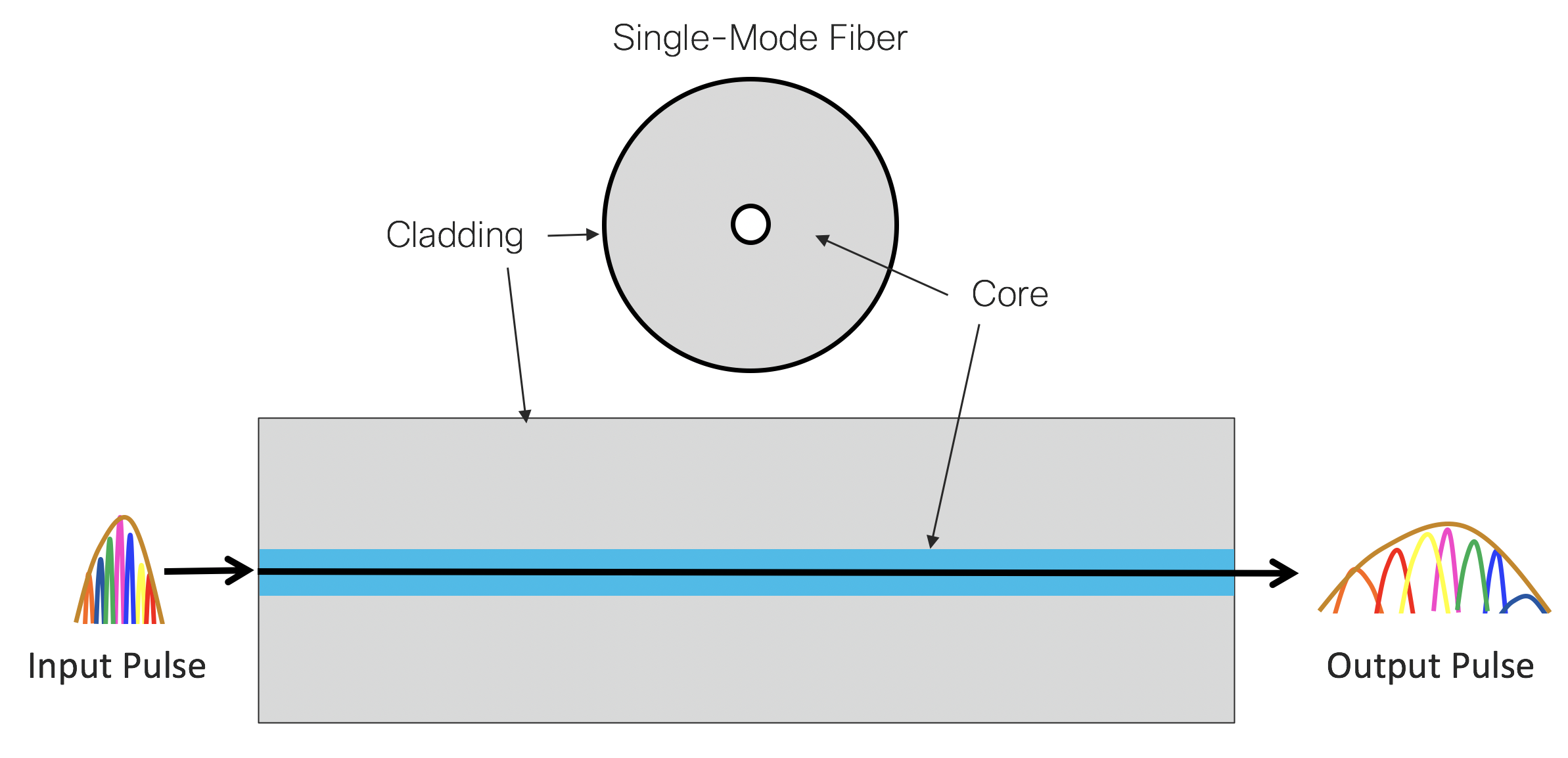
Light is an electromagnetic wave composed of a traveling electric and magnetic field. Single-mode fiber supports one propagation mode, which in turn is comprised of two orthogonal polarization modes, or states. If traveling through a perfectly cylindrical optical fiber, both polarization states would travel at exactly the same speed. However, in the real world there are stresses and manufacturing flaws in the optical fiber causing it to be non-cylindrical. These asymmetrical variations introduce small refractive index variations between the two states. Although each variation by itself is minuscule, the accumulation over tens of kilometers of fiber causes the polarization states to travel at noticeably different speeds. The light pulses then spread out in time, and have undergone polarization mode dispersion.
We offer a comprehensive product range for software-supported fully automatic measurement of the modulation transfer function (MTF) for both R&D and production or optics manufacturing.
Modern MTF- Testers like the ImageMaster® use a single illuminated slit on an opaque background as the object. From a mathematical point of view a single slit can be regarded as the sum over all spatial frequencies (Fourier synthesis). All frequencies contribute with the same amplitude (=1) to this slit, not taking the finite slit width into account for this description. This single slit will be imaged into the image plane of the sample. Due to diffraction and aberrations, there will be no perfect slit image in this plane, instead the slit image is broadened. It represents the Line Spread Function (LSF).
In a Part 2 of this series of posts, Priya described the two main types of optical fiber: single-mode and multi-mode. Now we look deeper into limitations of high-speed networks, when optical data propagates through the fiber from transmitter to receiver. We focus on fiber dispersion.
TRIOPTICS offers a broad product portfolio in the field of MTF measurement. This also includes model variants for measurement requirements that result from the latest technology trends for smartphone camera optics.
Materialdispersion
The modulation transfer function (MTF) is the generally accepted and fundamental parameter for the characterization of optical systems worldwide. MTF is a quantitative measure as well as an objective criterion for the imaging quality of optics.
Alternatively, it is also possible to use a cross (i.e. two perpendicular slits) for the target. This enables the ImageMaster® to measure the MTF in two image directions simultaneously provided a CCD camera is used for the image analyzer. And finally, a pinhole target can be used as the object, too. The image of a pinhole target is called the Point Spread Function. This function contains the complete MTF information in all image directions. The basic terms and mathematical relations used for MTF are described in the ISO 9334 standard.
When an object (illuminated target or reticle) is observed with an optical system, the resulting image will be somewhat degraded due to inevitable aberrations and diffraction phenomena. In addition, a real lens will not fully conform with the design data. Manufacturing errors, assembly and alignment errors in the optics will deteriorate the overall imaging performance of the system.
Chromatic dispersion is measured in ps/nm/km. This can be read as: For every km traveled in fiber, a pulse with 1 nm wavelength spectral width will spread by 1 ps. The amount of chromatic dispersion in optical fiber varies based on the wavelength.
Lenses can vary in their imaging quality during production. To meet the often high demands on imaging performance, lenses are characterized and evaluated using MTF as the most important parameter. MTF provides a meaningful quality function for the objective evaluation of optical systems in the optical industry. When it comes to imaging an object with the desired accuracy, MTF data provide the necessary basis for optical design. Resolution and contrast are of particular importance. MTF data can greatly simplify the selection of the appropriate lens for an application.
Dispersionin Physics
Optical dispersionformula
The MTF is a tool for optical designers to quantify the overall imaging performance of a system in terms of resolution and contrast. Knowledge of the MTF curves of the lenses and camera sensors involved in an optical system is used for optimization of the optical system performance.
Single-mode fiber is not affected by modal dispersion since it supports only one mode. However it is affected by material dispersion. There are two dispersion effects specific to single mode fiber that cause the light pulses to spread out. These are chromatic dispersion and polarization mode dispersion (PMD).
An analogy would be that of a car race where the blue car arrives the finish line faster than the red car. Here, the blue wavelength travels faster than the red wavelength.
The Modulation Transfer Function (MTF), describing the resolution and performance of an optical system, is the ratio of relative image contrast divided by relative object contrast.
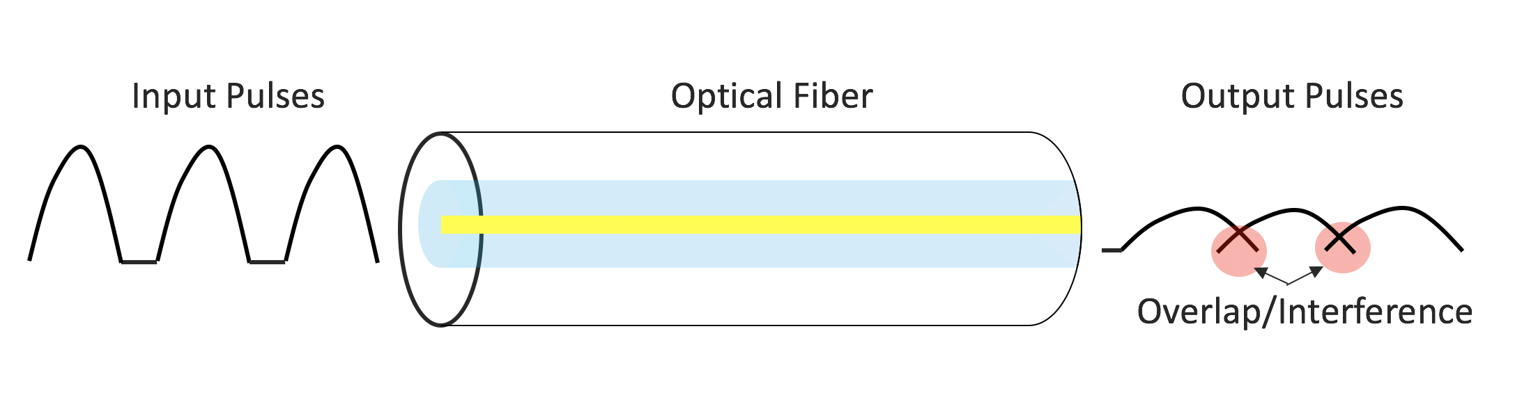
Optical data signals are comprised of very short bursts of light, or optical pulses. When we transmit optical pulses through fiber, they broaden. This means that they become longer in duration as they travel through the fiber. If the fiber is long enough, this broadening causes the pulses to overlap and interfere with each other, which impacts the receiver’s ability to resolve the transmitted data, resulting in bit errors. This pulse broadening is due to a phenomenon called dispersion and limits the transmission bandwidth and distance. Single-mode and multi-mode fiber are each dominated by different types of dispersion.
To completely characterize the imaging performance of an optical system, the MTF must be measured at different positions within the field of view. The MTF measurement within the field of view is known as off-axis measurement. In order to achieve an off-axis measurement, the target is moved in the field of view at the desired object position and the image analyzer to the corresponding image position.
MTF measurement usually comprises the optics under test and additional measurement or relay optics. Our whitepaper shows that the theoretical measurement error can increase significantly when using low-quality measuring optics which are not correctly optimized for MTF measurement.
The MTF measurement can be accomplished at a single wavelength or in a spectral range covering a finite band of wavelengths. The resulting measurement data are known as monochromatic or polychromatic MTF values, respectively.
In the real world a light source is never purely monochromatic (single wavelength). Instead, it is composed of different wavelengths at varying intensities near the center wavelength, such as 1310nm or 1550 nm. This is especially true for an optical pulse carrying digital information. The wavelengths experience different refractive indexes in the glass fiber, causing the shorter wavelengths to travel faster than the longer wavelengths. The optical pulse spreads out as it travels along the fiber. This dispersion is called chromatic dispersion, and is more pronounced at higher data rates.
Dispersioninopticalfiber
For years, the ImageMaster® PRO product family has set the global standard for testing the imaging quality of mobile phone camera lenses in mass production.
The modulation transfer function varies in relation to the spatial frequency and also with the position in the field of view. The MTF measurement along the axis of symmetry of the optical system is known as on-axis measurement.
Modaldispersion
One new technology in the mobile phone market is under-display camera technology – camera optics are almost invisibly hidden under full-screen display surfaces.
High-resolution, professional photography and the zoom capability of cameras are two further key drivers for the future. All three trends cause new challenges for measurement technology, for which TRIOPTICS is introducing customized measurement solutions for image quality testing.
The Modulation Transfer Function (MTF) is an important aid to objective evaluation of the image-forming capability of optical systems. Not only that, the MTF also provides a means of expressing the imaging quality of optical systems objectively and quantitatively, but it can be calculated from the lens design data. In this way it allows optical and systems designers to predict reliably the performance of the optical systems. Manufacturers can compare the image quality of the manufactured lenses with the design expectations.
This article inspired you? Are you looking for further knowledge transfer? Then you might also be interested in the following topics …
MTF is used for a wide range of optics from simple components such as spherical single lenses to complex lenses. Examples include photolithographic optics, intraocular lenses, endoscopes, riflescopes, telescopes, spotting scopes, binoculars, AR/VR optics, cine lenses, automotive lenses and many others.
Mike, Thank you for your kind remarks. I’m impressed with the team too. By the way, I didn’t know that you took part in the historic inception of the fiber optics industry! I’m sure you must have stories from those days. Best, Pat
With the three new developments of the ImageMaster® PRO series TRIOPTICS underlines its technology leadership also for the production of future mobile phone camera lenses.
Usually, the MTF is used in its one-dimensional form, calculated for one azimuthal section through the image plane. The azimuth (section plane) of the object pattern is called the sagittal azimuth when the prolongation of the slit or object passes through the reference axis. When the prolongation of the slit pattern is perpendicular to the reference axis, the azimuth is called the tangential azimuth.


 Ms.Cici
 8618319014500