
Laser Power Measurement - laser energy measurement
Example 1: Camera MagnificationWhen imaging a sample with a camera, the image is magnified by the objective and the camera tube. If using a 20X Nikon objective and a 0.75X Nikon camera tube, then the image at the camera has 20X × 0.75X = 15X magnification.
Objectives that feature a built-in iris diaphragm are ideal for darkfield microscopy. The iris diaphragm is designed to be partially closed during darkfield microscopy in order to preserve the darkness of the background. This is absolutely necessary for high numerical aperture (above NA = 1.2) oil immersion objectives when using an oil immersion darkfield condenser. For ordinary brightfield observations, the iris diaphragm should be left fully open.
Using an immersion fluid with a high refractive index allows objectives to achieve numerical apertures greater than 1.0. However, if an immersion objective is used without the fluid present, the image quality will be very low. Objectives following ISO 8578: Microscopes -- Marking of Objectives and Eyepieces will be labeled with an identifier ring to tell the user what immersion fluid the objective is designed to be used with; a list of ring colors can be found in the table above.
As the magnification increases, the resolution improves, but the field of view also decreases. The dependence of the field of view on magnification is shown in the schematic to the right.
The working distance, often abbreviated WD, is the distance between the front element of the objective and the top of the specimen (in the case of objectives that are intended to be used without a cover glass) or top of the cover glass. The cover glass thickness specification engraved on the objective designates whether a cover glass should be used.
These phase contrast objectives are ideal for phase contrast with multiple illumination modalities, such as brightfield and epi-fluorescence. They feature a larger numerical aperture for higher light transmission at the sacrifice of less contrast than the apodized phase contrast objective sold below. In addition, these plan fluorite objectives feature aberration correction at four wavelengths and correction of field curvature. A Ph1 phase mask is included for use with a compatible Nikon condenser.
This phase contrast objective features a second neutral density ring on either side of the central phase ring. The secondary rings introduce an additional amplitude filter to the central phase ring, thereby reducing halo artifacts common to imaging large particles or specimen features. This objective provides a stronger contrast for large refractive index changes in the sample compared to the objectives above; it is ideal for general purpose applications such as cellular imaging and photomicography. In addition, this achromat objective incorporates aberration correction at two wavelengths. A Ph1 phase mask is included for use with a compatible Nikon condenser.
Magnification is not a fundamental value: it is a derived value, calculated by assuming a specific tube lens focal length. Each microscope manufacturer has adopted a different focal length for their tube lens, as shown by the table to the right. Hence, when combining optical elements from different manufacturers, it is necessary to calculate an effective magnification for the objective, which is then used to calculate the magnification of the system.
The shoulder is located at the base of the objective threading and marks the beginning of the exposed objective body when it is fully threaded into a nosepiece or other objective mount.
The labeling area for an objective usually falls in the middle of the objective body. The labeling found here is dictated by ISO 8578: Microscopes -- Marking of Objectives and Eyepieces, but not all manufacturers adhere strictly to this standard. Generally, one can expect to find the following information in this area:
In the rapidly expanding fields of cellular and molecular biology, widefield and confocal fluorescence illumination and observation is becoming one of the techniques of choice. These techniques, which are almost universally employed in both the medical and biological sciences, have spurred the development of more sophisticated microscopes and numerous fluorescence accessories.
The camera sensor dimensions can be obtained from the manufacturer, while the system magnification is the multiplicative product of the objective magnification and the camera tube magnification (see Example 1). If needed, the objective magnification can be adjusted as shown in Example 3.
Five objective classes are shown in the table to the right; only three common objective classes are defined under the International Organization for Standards ISO 19012-2: Microscopes -- Designation of Microscope Objectives -- Chromatic Correction. Due to the need for better performance, we have added two additional classes that are not defined in the ISO classes.
Phasecontrastmicroscopeparts
John D. Griffin, Nathan S. Claxton, Matthew J. Parry-Hill, Thomas J. Fellers, Kimberly M. Vogt, Ian D. Johnson, Shannon H. Neaves, Omar Alvarado, Lionel Parsons, Jr., Michael A. Sodders, Richard L. Ludlow, and Michael W. Davidson - National High Magnetic Field Laboratory, 1800 East Paul Dirac Dr., The Florida State University, Tallahassee, Florida, 32310.
Here, the Design Magnification is the magnification printed on the objective, fTube Lens in Microscope is the focal length of the tube lens in the microscope you are using, and fDesign Tube Lens of Objective is the tube lens focal length that the objective manufacturer used to calculate the Design Magnification. These focal lengths are given by the table to the right.
Immersion objectives are similar to water-dipping objectives; however, in this case the sample is under a cover glass. A drop of fluid is then added to the top of the cover glass, and the tip of the objective is brought into contact with the fluid. Often, immersion objectives feature a correction collar to adjust for cover glasses with different thicknesses. Immersion fluids include water, oil (such as MOIL-30), and glycerol.
Phasecontrastmicroscopeprinciple
Example 3: Trinocular Magnification (Different Manufacturers)When imaging a sample through trinoculars, the image is magnified by the objective and the eyepieces in the trinoculars. This example will use a 20X Olympus objective and Nikon trinoculars with 10X eyepieces.
This microscope objective serves only as an example. The features noted above with an asterisk may not be present on all objectives; they may be added, relocated, or removed from objectives based on the part's needs and intended application space.
Explore alignment and focusing of the arc lamp in a mercury or xenon burner, which simulates how the lamp is adjusted in a real microscope.
Phasecontrastmicroscopediagram
Images can also exhibit chromatic aberrations, where colors originating from one point are not focused to a single point. To strike a balance between an objective's performance and the complexity of its design, some objectives are corrected for these aberrations at a finite number of target wavelengths.
Jennifer C. Waters - Nikon Imaging Center, LHRRB Room 113C, Department of Cell Biology, Harvard Medical School, 240 Longwood Avenue, Boston, Massachusetts, 02115.
Objectives can be divided by what medium they are designed to image through. Dry objectives are used in air; whereas dipping and immersion objectives are designed to operate with a fluid between the objective and the front element of the sample.
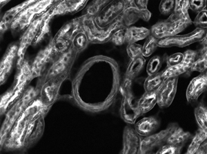
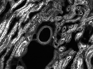
The images of a mouse kidney below were all acquired using the same objective and the same camera. However, the camera tubes used were different. Read from left to right, they demonstrate that decreasing the camera tube magnification enlarges the field of view at the expense of the size of the details in the image.
To adapt the examples shown here to your own microscope, please use our Magnification and FOV Calculator, which is available for download by clicking on the red button above. Note the calculator is an Excel spreadsheet that uses macros. In order to use the calculator, macros must be enabled. To enable macros, click the "Enable Content" button in the yellow message bar upon opening the file.
Multiple optical elements, including the microscope objective, tube lens, and eyepieces, together define the magnification of a system. See the Magnification & FOV tab to learn more.
Phasecontrastmicroscopeapplication
Dipping objectives are designed to correct for the aberrations introduced by the specimen being submerged in an immersion fluid. The tip of the objective is either dipped or entirely submerged into the fluid.
Example 4: Sample AreaThe dimensions of the camera sensor in Thorlabs' previous-generation 1501M-USB Scientific Camera are 8.98 mm × 6.71 mm. If this camera is used with the Nikon objective and trinoculars from Example 1, which have a system magnification of 15X, then the image area is:
In the case of positive phase contrast, a high-refractive-index plate inside the objective utilizes a metal-coated, etched ring to both reduce transmission by 50% and introduce a +¼λ phase shift to light traveling through the ring. When used with the matching condenser annulus, the beam passing through the phase ring primarily contains background, unscattered light, while the beam passing elsewhere through the plate corresponds to light scattered by the sample. Light interaction with the specimen results in a typical -¼λ phase shift for cellular structures. The net 180° phase difference (typical) between the unscattered and scattered portions of the beam results in constructive and destructive interference at the image plane. The 50% reduction in background light results in a more comparable intensity between background and scattered light, additionally improving contrast. Compared to brightfield images, phase contrast images exhibit larger, phase-dependent contrast with lower background signal. Because these objectives utilize positive phase contrast, the resulting image will be dark with a light background.
George H. Patterson and Jennifer Lippincott-Schwartz - Cell Biology and Metabolism Branch, National Institute of Child Health and Human Development, National Institutes of Health, Bethesda, Maryland, 20892.
In order to facilitate fast identification, nearly all microscope objectives have a colored ring that circumscribes the body. A breakdown of what magnification each color signifies is given in the table below.
Note that Leica, Mitutoyo, Nikon, and Thorlabs use the same tube lens focal length; if combining elements from any of these manufacturers, no conversion is needed. Once the effective objective magnification is calculated, the magnification of the system can be calculated as before.
The most common, a standard #1.5 cover glass, is designed to be 0.17 mm thick. Due to variance in the manufacturing process the actual thickness may be different. The correction collar present on select objectives is used to compensate for cover glasses of different thickness by adjusting the relative position of internal optical elements. Note that many objectives do not have a variable cover glass correction, in which case the objectives have no correction collar. For example, an objective could be designed for use with only a #1.5 cover glass. This collar may also be located near the bottom of the objective, instead of the top as shown in the diagram.
PhasecontrastmicroscopePDF
Explore how the variations in the excitation and emission filter spectral profiles affect signal levels, overall filter performance, and image contrast in combinations designed for dual excitation of fluorophores in the ultraviolet and blue or blue and green regions.
Objectives are commonly divided by their class. An objective's class creates a shorthand for users to know how the objective is corrected for imaging aberrations. There are two types of aberration corrections that are specified by objective class: field curvature and chromatic aberration.

Threading allows an objective to be mounted to a nosepiece or turret. Objectives can have a number of different thread pitches; Thorlabs offers a selection of microscope thread adapters to facilitate mounting objectives in different systems.
Field curvature (or Petzval curvature) describes the case where an objective's plane of focus is a curved spherical surface. This aberration makes widefield imaging or laser scanning difficult, as the corners of an image will fall out of focus when focusing on the center. If an objective's class begins with "Plan", it will be corrected to have a flat plane of focus.
The effective magnification of the Olympus objective is 22.2X and the trinoculars have 10X eyepieces, so the image at the eyepieces has 22.2X × 10X = 222X magnification.
Thorlabs provides a selection of Nikon dry objectives designed for phase contrast microscopy. These objectives use a phase plate at the rear focal plane of the objective with a coated phase ring. The ring introduces a +¼λ phase shift to light passing through the ring. Light which does not pass through the ring, which consists primarily of light scattered by sample features, receives a typical phase shift of -¼λ. This results in a 180° phase shift (typical) between background and scattered light. Constructive and destructive interference between light scattered by the sample and background illumination results in higher image contrast than can be achieved through brightfield illumination alone.
To achieve optimum phase contrast, these phase contrast objectives should be used with the included Ph1 phase annulus; the diameter of the annulus is paired to the diameter of the phase ring of the objective. The phase mask should be installed in a Nikon condenser containing a compatible slot, such as the CSC1002 condenser. See the Phase Contrast tab for details.
Objectives with very small working distances may have a retraction stopper incorporated into the tip. This is a spring-loaded section which compresses to limit the force of impact in the event of an unintended collision with the sample.
When imaging a translucent sample via brightfield trans-illumination, the contrast between the sample and background can be minimal, as it only depends on absorption. Phase contrast microscopy increases image contrast by converting phase changes into amplitude changes at the image plane.
Explore the light paths in Nikon's SMZ1500 stereomicroscope equipped for fluorescence illumination using an intermediate tube and external lamphouse.
Exploring how the variations in the excitation and emission filter spectral profiles, as well as those of the dichromatic mirrors, affect signal levels, overall filter performance, and image contrast in combinations designed for excitation of fluorophores in the blue-violet region.
These objectives feature M25 x 0.75 threading and a 60 mm parfocal length; to use one of these objectives alongside an objective with a longer parfocal length, such as for multiphoton microscopy, we offer the PLE153 Parfocal Length Extender to increase the parfocal length from 60 mm to 75 mm. To convert M25 x 0.75 threads to M32 x 0.75 threads, we offer the M32M25S brass thread adapter.
These objectives are designed for tube lenses with a 200 mm focal length, such as our series of TTL200 infinity-corrected tube lenses.
Douglas B. Murphy - Department of Cell Biology and Anatomy and Microscope Facility, Johns Hopkins University School of Medicine, 725 N. Wolfe Street, 107 WBSB, Baltimore, Maryland 21205.
Jason R. Swedlow and Paul D. Andrews - Division of Gene Regulation and Expression, MSI/WTB Complex, University of Dundee, Dundee DD1 5EH, Scotland.
Also referred to as the parfocal distance, this is the length from the shoulder to the top of the specimen (in the case of objectives that are intended to be used without a cover glass) or the top of the cover glass. When working with multiple objectives in a turret, it is helpful if all of the parfocal distances are identical, so little refocusing will be required when switching between objectives. Thorlabs offers parfocal length extenders for instances in which the parfocal length needs to be increased.
Phasecontrastmicroscopeadvantages and disadvantages
Phasecontrastmicroscopeppt
The Nikon blue excitation fluorescence filter combinations include bandpass and longpass sets having both broad and narrow excitation bandwidths.
If an objective is used for water dipping, water immersion, or oil immersion, a second colored ring may be placed beneath the magnification identifier. If the objective is designed to be used with water, this ring will be white. If the objective is designed to be used with oil, this ring will be black. Dry objectives lack this identifier ring entirely. See the table to the right for a complete list of immersion identifiers.
Phasecontrastmicroscopeimages
Additionally, the objective label area may include the objective's specified wavelength range, specialty features or design properties, and more. The exact location and size of each and any of these elements can vary.
When imaging a sample with a camera, the dimensions of the sample area are determined by the dimensions of the camera sensor and the system magnification, as shown by Equation 2.
Stephen T. Ross, Anna Scordato, and Stanley Schwartz - Bioscience Department, Nikon Instruments, Inc., 1300 Walt Whitman Road, Melville, New York, 11747.
Following Equation 1 and the table to the right, we calculate the effective magnification of an Olympus objective in a Nikon microscope:
Alexey Khodjakov and Conly L. Rieder - Wadsworth Center, New York State Department of Health, Albany, New York, 12201, and Marine Biological Laboratory, Woods Hole, Massachusetts, 02543.
A cover glass, or coverslip, is a small, thin sheet of glass that can be placed on a wet sample to create a flat surface to image across.
The magnification of a system is the multiplicative product of the magnification of each optical element in the system. Optical elements that produce magnification include objectives, camera tubes, and trinocular eyepieces, as shown in the drawing to the right. It is important to note that the magnification quoted in these products' specifications is usually only valid when all optical elements are made by the same manufacturer. If this is not the case, then the magnification of the system can still be calculated, but an effective objective magnification should be calculated first, as described below.
Michael E. Dailey - Department of Biological Sciences and Neuroscience Program, 369 Biology Building, University of Iowa, Iowa City, Iowa, 52242.
Example 2: Trinocular MagnificationWhen imaging a sample through trinoculars, the image is magnified by the objective and the eyepieces in the trinoculars. If using a 20X Nikon objective and Nikon trinoculars with 10X eyepieces, then the image at the eyepieces has 20X × 10X = 200X magnification. Note that the image at the eyepieces does not pass through the camera tube, as shown by the drawing to the right.
Explore how the variations in the excitation and emission filter spectral profiles affect signal levels, overall filter performance, and image contrast in combinations designed for excitation of fluorophores in the green (510-560 nanometers) spectral region.
Objectives following ISO 8578: Microscopes -- Marking of Objectives and Eyepieces will be labeled with an identifier ring to tell the user what immersion fluid the objective is designed to be used with; a list of ring colors can be found in the table to the right.
Objectives following ISO 8578: Microscopes -- Marking of Objectives and Eyepieces will be labeled with an identifier ring to tell the user what immersion fluid the objective is designed to be used with; a list of ring colors can be found in the table to the right.


 Ms.Cici
 8618319014500