
Laser Enhancement Safety Glasses - Homedepot.ca - laser protection glasses
Zinc selenide windowcost
Since the minimum extent of the ray bundle occurs at the image location, that is the optimal location for the light-guide entrance face[2] in terms of coupling efficiency. The transverse magnification of the image MT is given by MT = di/dLED = f /(dLED – f ), where dLED is the distance from the LED to the lens, and di is the distance from the lens to the image of the LED. Thus, if the LED has transverse extent DLED and the light guide has transverse extent DLG, the closest the LED may be brought to the lens without some of the LED image falling outside the light-guide entrance is dclosest = f (1 + DLED/DLG).
[3] This is due to conservation of étendue – a fundamental optica-design constraint I will mention again at the end of the blog.
Zinc Selenidelens
Although LEDs are particularly awful at producing directed light, light guides are particularly indiscriminate in their acceptance of “poorly directed” light.
Join over 6000 medical device professionals who receive our engineering, regulatory and commercialization insights and tips every month.
The performance capabilities of such a “light conduit” can only be realized if light can be successfully coupled into the conduit in the first place! One can imagine a never-ending succession of Rube-Golberg-like optical schemes to accomplish this goal. In practice, the number of efficient schemes is actually quite limited. In this blog, I’ll discuss several of these schemes and why other strategies will have more limited success in coupling light from LEDs and light guides.
Most of the above discussion can be captured by a concept known as conservation of etendue – which states that the product of the angular extent of a ray bundle and its cross-sectional area is unchanged by any optical element. The inherently high angular extent of light from LEDs causes optical designs to tend to run aground in this conservation principle. However, that would be the subject of a whole other blog! In the meantime, just remember that to maximize coupling light from LEDs and light guides in medical devices, put the light-guide entrance face as close as possible to the LED output face.
[4] In order to perform a more-quantitative assessment, compare the luminous efficiency of the lensed vs. unlensed varieties of the LED.
Germaniumwindow
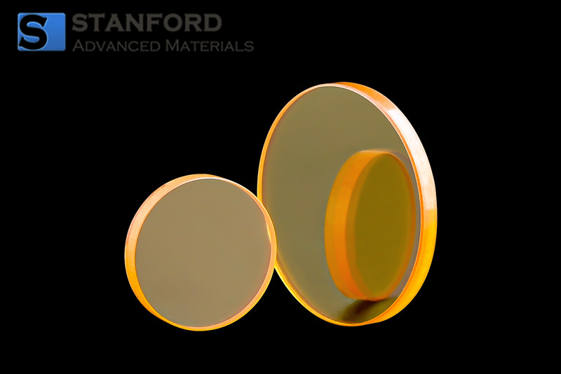
Zinc Selenide Window (ZnSe) features the ability to withstand thermal shock making it an optical material in CO2 laser systems. Stanford Advanced Materials (SAM) boasts extensive experience in providing Optical Products with both high purity and competitive pricing.
Zinc selenideSDS
Hence, the general guideline for maximal coupling of light into light guides: put the light-guide entrance face as close as possible to the LED output face. That way, the light guide entrance subtends the largest-possible (solid-) angle as seen from the LED output face – the LED light “sees light guide no matter which way it looks…” An optical designer may be tempted to put a lens in between the LED and the light guide to enhance the amount of light coupled in. There may be good reasons to interpose a lens (for example, to make a more-collimated far-field beam at the light-guide exit). However, in terms of coupling efficiency, this generally hurts: it effectively moves the light-guide further from the LED, thus reducing the fraction of light it can capture.
Our Zinc Selenide Window (ZnSe) is carefully handled during storage and transportation to preserve the quality of our product in its original condition.
Similarly, if the LED is located farther than 2f from the lens, a smaller-than-life image of the LED is created on the other side of the lens. The light guide entrance face may be placed anywhere the converging (or post-image diverging) bundle of rays is of a smaller extent than the light guide image. On the other hand, in this scenario, the lens captures less light than it otherwise could, which is non-optimal.
As a prelude to the following discussion, it’s worthwhile thinking about how Snell’s law of refraction pertains to light leaving an LED, and to light entering the light guide.
Some LED manufacturers immerse the semiconductor in a flat or curved epoxy layer, whose index of refraction is intermediate between that of the semiconductor and that of air. This epoxy somewhat reduces reflection losses but doesn’t fundamentally change the circumstances. In the cases in which this layer is curved, it acts as a first lens in the optical system – and the general discussion of lenses below still pertains.
Zinc SelenideOptics
Zinc selenide windowprice
Figure 3: Passing light from an LED through a simple positive lens, as the location dLED of the LED is varied with respect to the LED position. (a) If the LED lies inside the lens’s focal distance f, then the light rays from the LED diverge after the lens. A similar situation results if the positive lens is replaced by a negative one. (b) If the LED lies between f and 2f from the lens, a magnified real image of the LED is formed on the far side of the lens. (c) If the LED lies further than 2f from the lens, a de-magnified image is formed, a distance dimage that is further from the lens than is f.
On the other hand, if the LED is located a distance from the lens that lies between f and 2f, a magnified image of the LED is created on the other side of the lens. In this situation, if the magnified image is larger than the Iight-guide entrance aperture, light is lost.
[1]Rays that hit the side of a light guide generally don’t experience TIR when they strike the far side, and simply pass on through.
Zinc Selenidetransmission spectrum
There’s one more configuration – used by LED manufacturers – that’s worth discussing: one in which the lens material encases the LED emitter. None of the above considerations are different. However – and this is key – if the light from the LED leaves the semiconductor entering into a material with a higher index than air, the critical angle is increased and more light can escape the semiconductor. If the other side of the higher-index material (e.g. epoxy) has positive curvature, the angle of incidence onto the air interface can be reduced, thus reducing the Fresnel losses at that surface as well.
[2] One may move the light-guide entrance towards or away from the lens somewhat and still capture all the rays, so long as the LED’s ray bundle extent is smaller than the light-guide entrance.
In the above discussion, I was assuming a plano-convex or biconvex lens. A more attractive option would be a positive-power meniscus lens – such a lens can “wrap around” the LED, thus capturing more light. This is what LED manufacturers often do – in so-called “lensed LEDs.” The lens creates a magnified image of the LED – but a magnified image implies a lowering of ray-bundle divergence, as Figure 3 shows. Thus, the LED output may be more collimated than for a bare emitter.
Window is one of the basic optical components in optics. It is usually used as a protective window for electronic sensors or detectors of the external environment. It is used to separate the environment on both sides, such as separating the inside and outside of the instrument, to isolate the inside and outside of the instrument from each other, thereby protecting the internal components. Windows do not change the system's magnification.
Please fill in your RFQ details and one of sales engineers will get back to you within 24 hours. If you have any questions, You can call us at 949-407-8904 (PST 8am to 5pm).
I’ll discuss these nuances in two cases: in which the light-guide entrance is larger than the LED exit face, and in which the LED exit face is larger than the light-guide entrance.
Zinc seleniderefractive index
However, though light guides’ acceptance angle is large, the size of their entrance face is always limited to some extent. And – regardless of propagation angle – a ray of light can only enter the light guide if it actually hits the entrance face![1]
Since semiconductors are epitaxially grown, almost all LED emitters will have a flat face. Therefore, LEDs generically tend to internally capture a substantial portion of their optical output and to send what light does escape in all directions up to ±90°. Further, for most LEDs, this angular spread is mostly uniform: that is, the LED is a good approximation to a Lambertian emitter (see Figure 2), and the angular distribution of light is pretty much as uniform as it can be in 3D space. Catching this light and directing it somewhere can pose a challenge.
Light guides (also called “light pipes”) work through total internal reflection (TIR). If light travels from a material with a higher index of refraction to one with a lower index, and the angle of incidence ϴwall on the interface exceeds a critical angle , then 100% of the light is reflected off the interface, and back into the interior of the first material (see Figure 1). Such a surface makes an ideal “mirror.” In principle, light inside such a light guide will be reflected from one end of the guide to the other without loss – barring changes in guide geometry (e.g. bends, scratches) or absorption in the guide material.
This is an important consideration: at the end of the day, the lens is – at best – sending all the light that strikes it to the light-guide entrance. But that’s all it can send! So the further the lens from the LED, the less LED light it captures in the first place. Another way to think of the above formula is that if the lens can be no closer than dclosest due to some design constraint, then (a) the lens should be chosen to be as large as possible, to intercept as much light as possible, and (b) the focal length of the lens should be chosen such that f = dclosest/(1 + DLED/DLG). One might imagine more complex, multi-lens designs to escape this constraint. However, because most LEDs’ output is fundamentally distributed uniformly in all directions, such designs will still miss the light that would otherwise be captured by simply moving the light guide entrance up to the LED[3].
Figure 2: The angular-emission pattern of a typical bare-chip LED, compared to an ideal (“Lambertian”) emitter that radiates uniformly into all directions of the hemisphere. The agreement is quite striking. (Note: The falloff with angle is due to the increase in surface area of a unit sphere as the direction moves from being directly overhead to more aligned with the cut-plane of the hemisphere – see inset.)
Brian King is Principal Optical Systems Engineer at StarFish Medical. Previously, he was Manager of Optical Engineering and Systems Engineering at Cymer Semiconductor, Brian was an Assistant Professor at McMaster University. Brian holds a B.Sc in Mathematical Physics from SFU, and an M.S. and Ph.D. in Physics from the University of Colorado at Boulder.
Zinc Selenide Window (ZnSe) features the ability to withstand thermal shock making it an optical material in CO2 laser systems. The hardness is only 2/3 of multispectral ZnS, the material is soft and prone to scratches, and the material has a high refractive index, so it needs to be coated with an anti-reflective film on its surface to protect it and gain transmittance.


 Ms.Cici
 8618319014500