
Kees Van Der Westen Brass Fitting (0.25 mm, 0.375 mm) - 0.375 mm
What areopticalfilters used for
To attain higher working numerical apertures, many objectives are designed to image the specimen through another medium that reduces refractive index differences between glass and the imaging medium. High-resolution plan apochromat objectives can achieve numerical apertures up to 1.40 when the immersion medium is special oil with a refractive index of 1.51. Other common immersion media are water and glycerin. Objectives designed for special immersion media usually have a color-coded ring inscribed around the circumference of the objective barrel as listed in Table 3 and described below. Common abbreviations are: Oil, Oel (oil immersion), HI (homogeneous immersion), W, Water, Wasser (water immersion), and Gly (glycerol immersion).
Parfocal Distance - This is another specification that can often vary by manufacturer. Most companies produce objectives that have a 45 millimeter parfocal distance, which is designed to minimize refocusing when magnifications are changed.
Like the optical filters, the beam splitters are also available as long pass, short pass, multiband pass, notch and neutral beam splitters. Bandpass beam splitters with one band are not common. In general, it should be noted that beam splitters can have a high transmission – but do not have a high blocking. The average blocking of beamsplitters is about OD3 (O.1% transmission) and does not match the high blocking of optical filters, which is about OD6 (0.0001% transmission). I.e. beam splitters are used to 'sort' the light but not to block unwanted light. This is what the optical filters are used for.
From the discussion above it is apparent that objectives are the single most important element of a microscope. It is for this reason that so much effort is invested in making sure that they are well-labeled and suited for the task at hand.
This optical bandpass filter transmits the light around the central wavelength of 525nm with a bandwidth of 50nm. Outside the band the optical filter blocks the remaining wavelengths: Consequently, a band is 'cut' out of the spectrum which can be used further.
Optical short pass filters transmit the light in the short wavelength range and block the light in the long wavelength range. A cut-off wavelength defines the edge and depending on the quality and complexity of the filter, this edge has a different steepness. The more layers are applied, the faster the edge falls off and, depending on the application, more valuable light can be used.
Optical Filterprice
Investigate how internal lens elements in a high numerical aperture dry objective may be adjusted to correct for fluctuations in coverslip thickness.
What is sketched here as an example with one layer is, in the case of complex (steep-edged) filters, hundreds of layers of different materials, which are reproducibly applied homogeneously and evenly to a carrier material.
For more information on the flatness of beamsplitters, please contact Turan Erdogan, IDEX/Semrock: Optical Filters: Flatness (PDF)
Important note: The parallel arrangement of optical interference filters increases blocking only marginally, since the light that is not transmitted is reflected and not absorbed.
Optical filterdesign
When looking at the edge in the blocking diagram, it becomes obvious how steep the edge falls. Within 3-4 nm a blocking of six orders of magnitude from OD0.1 to OD6 is achieved.
As an example we use the 532nm short pass filter » 532 SP Edge Basic (Art. No. F76-535). In the illustration of the transmission of the optical short pass filter the edge at 532nm in connection with the transmission in the short wavelength range and the wide blocking up to 1200nm is clearly visible.
The 'CHA' (cone half angle) and 'AOI' (angle of incidence) influence the transmitted spectrum of optical interference filters. The layer thickness on the substrate depends on the incident wavelength. If the angle of the incident light changes, the path of the light through the applied layer also changes relatively to this - and thus the spectral properties of the optical filter.
Functional cookies are absolutely necessary for the functionality of the website. These cookies assign a unique random ID to your browser to ensure unhindered use of the website across multiple page views.
The flatness of the beam splitter is most critical when the whole image of the sample is reflected by the beam splitter. This is when the Imaging beam splitters are used. These are designed for this purpose and have an exceptional flatness. In general, it should be noted that the information on flatness from different manufacturers is not uniform and therefore not directly comparable. Please contact us, we will be pleased to advise you!
Michael W. Davidson - National High Magnetic Field Laboratory, 1800 East Paul Dirac Dr., The Florida State University, Tallahassee, Florida, 32310.
These cookies are used to display advertisements on the website in a targeted and individualized manner across multiple page views and browser sessions.
The optica » pentaband filter (Art. No. F72-855) with the central wavelengths at 440nm, 521nm, 607nm, 694nm and 809nm serves as an example.
Some objectives specifically designed for transmitted light fluorescence and darkfield imaging are equipped with an internal iris diaphragm that allows for adjustment of the effective numerical aperture. Abbreviations inscribed on the barrel for these objectives include I, Iris, and W/Iris. The 60x apochromat objective illustrated above has a numerical aperture of 1.4, one of the highest attainable in modern microscopes using immersion oil as an imaging medium.
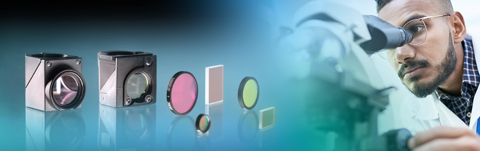
Optical filters play a key role in many biophysical measurement applications, like fluorescence microscopy and Raman spectroscopy, including super-resolution techniques. For these applications, we offer in collaboration with prestigious filter manufacturers a comprehensive portfolio as well as customized solutions. Besides an in-depth and expert consultation service, we can provide you with filter components for personal testing. Working closely with research-institutes and industry, we continuously optimize filter designs – an effort that has produced lasting collaborations with OEM partners.
For interference filters a blocking of measured OD6 is now common, which corresponds to a transmission of 0.0001%. Designed blockings can be much higher - but it is difficult to measure them accurately. Such high contrasts (nearly 100% transmission and blocking with OD6) are not nearly achievable with colored glasses (for close spectral points), so they are not suitable for fluorescence microscopy.
An optical notch filter is the inverse of a bandpass filter. Instead of transmitting one band, as with an optical bandpass filter, one band is blocked and the rest of the spectrum is transmitted. So when you look at the blocking of an optical notch filter, it is similar to the transmission of a bandpass filter. Typical applications for Notch Filters can be found in laser physics. In this case a notch filter is used to block the laser light and the remaining light is used. The » 594 nm notch filter (Art. No. F40-593):
These cookies are used to offer you further functions that make the use of the website more comfortable (e.g. a product wish or memo list).
Bandpassoptical filter
The difficulty with this filter is the very narrow band and the wide blocking. The suppression of the higher harmonics of the transmission band is complex and requires a very complex filter design.
There is a wealth of information inscribed on the barrel of each objective, which can be broken down into several categories. These include the linear magnification, numerical aperture value, optical corrections, microscope body tube length, the type of medium the objective is designed for, and other critical factors in deciding if the objective will perform as needed. A more detailed discussion of these properties is provided below and in links to other pages dealing with specific issues.
In fluorescence microscopy, optical filters are needed to clean the excitation and emission beams. These are usually dielectrically coated interference filters. First of all, the excitation filter spectrally filters the mostly white light of the excitation lamp in such a way that only that part of the light passes through which can be excited by the fluorescence markers. For example, the green fluorescent protein GFP is excited in the blue range. Due to the Stokes shift, the emission light of the fluorescent marker does a shift to the longer wavelength part of the spectrum.
The objective depicted on the left in Figure 3 has a parfocal distance of 45mm and is labeled with an immersion medium color code in addition to the magnification color code. Parfocal distance is measured from the nosepiece objective mounting hole to the point of focus on the specimen as illustrated in the figure. The objective on the right in Figure 3 has a longer parfocal distance of 60 millimeters, which is the result of its being produced to the Nikon CFI60 200/60/25 Specification, again deviating from the practice of other manufacturers such as Olympus and Zeiss, who still produce objectives with a 45mm parfocal distance. Most manufacturers also make their objective nosepieces parcentric, meaning that when a specimen is centered in the field of view for one objective, it remains centered when the nosepiece is rotated to bring another objective into use.
Not only one band can be realized with an optical bandpass filter. There are also dual band (two bands), triple band (three bands), quad band (four bands) and pentaband (five bands) optical filters.
Opticalfilters HS Code
Glass Design - The quality of glass formulations has been paramount in the evolution of modern microscope optics. Numerous designs have been implemented by a variety of manufacturers, but we will limit this discussion to a specialized low dispersion glass formulation. Extra Low Dispersion (ED) glass was introduced as a major advancement in lens design with optical qualities similar to the mineral fluorite but without its mechanical and optical demerits. This glass has allowed manufacturers to create higher quality objectives with lens elements that have superior corrections and performance.
The collected fluorescence light is then separated from the remaining, scattered excitation light by the emission filter. It is important to avoid any spectral overlap of the excitation filter and emission filter, otherwise a so-called 'bleed-through' of the excitation light – which is very strong compared to the emission light – will occur and destroy the usually excellent contrast of the images. The 'out-of-band blocking (suppression of unwanted wavelengths) is particularly decisive in this respect. For this reason, AHF analysentechnik only provides optical high-end filters that guarantee blocking from OD6 to OD8 in the relevant spectral ranges. Only this way, the fluorescence light can be measured virtually against a completely black background and makes individual molecules visible in a sufficient darkened room – even with the eye.
Optical beam splitters have the special characteristic that they are not designed to be used at an angle of incidence below 0 degrees (as with optical filters) but at an angle of incidence of 45 degrees. They are used to combine or separate two light paths. In fluorescence microscopy, for example, the excitation light is usually directed onto the sample via the beam splitter and the fluorescence signal from the sample is transmitted through the beam splitter to the user.
Transmission of the filters is another critical point. Only when these come close to the theoretical limit of >95%, shortest exposure times can be selected, which spares the markers because less light is needed for detection.
Optical filters are used to control or filter the light depending on its wavelength (color). Depending on its wavelength, the light can be transmitted, absorbed (swallowed) or reflected. For example, the aim can be to transmit blue light and reflect/absorb red light. Optical filters differ roughly in the way they work in that there are colored glasses and interference filters (dielectric-coated glasses). Both types have different advantages and disadvantages, as their mode of operation is different.
Most manufacturers have now transitioned to infinity-corrected objectives that project emerging rays in parallel bundles from every azimuth to infinity. These objectives require a tube lens in the light path to bring the image into focus at the intermediate image plane. Infinity-corrected and finite-tube length microscope objectives are not interchangeable and must be matched not only to a specific type of microscope, but often to a particular microscope from a single manufacturer. For example, Nikon infinity-corrected objectives arenot interchangeable with Olympus infinity-corrected objectives, not only because of tube length differences, but also because the mounting threads are not the same pitch or diameter. Objectives usually contain an inscription denoting the tube focal length correction as will be discussed.
You can find more on this topic in the presentation by Turan Erdogan, IDEX/Semrock: » Coherence and Combining Filters (PDF)
The interactive tutorial above allows the visitor to adjust the correction collar on a microscope objective. There are some applications that do not require objectives to be corrected for cover glass thickness. These include objectives designed for reflected light metallurgical specimens, tissue culture, integrated circuit inspection, and many other applications that require observation with no compensation for a cover glass.
Important properties of optical filters are their spectral characteristics. Wavelength dependent transmission and blocking is the main feature. The transmission of optical filters is given in % and in the best case it is close to 100%. The blocking of optical filters is given in OD (optical density) and is a logarithmic scale. OD0 corresponds to a blocking of 0 or a transmission of 100% - a blocking of OD1 corresponds to a transmission of 10% - OD2 / 1% - OD3 / 0.1% etc.
Optical bandpass filters are a combination of a short pass filter and a long pass filter. The result is a band that transmits light in a specific spectral range and reflects it otherwise.
World-class Nikon objectives, including renowned CFI60 infinity optics, deliver brilliant images of breathtaking sharpness and clarity, from ultra-low to the highest magnifications.
Types ofopticalfilters
Although not common today, other types of adjustable objectives have been manufactured in the past. Perhaps the most interesting example is the compound "zoom" objective that has a variable magnification, usually from about 4x to 15x. These objectives have a short barrel with poorly designed optics that have significant aberration problems and are not very practical for photomicrography or serious quantitative microscopy.
The coating on the substrate can cause tension which bends the beam splitter. This is more or less critical depending on the application. In the classical epi-fluorescence application (in combination with lamps) the image of the sample is transmitted through the beam splitter and therefore has little influence on the image quality. Here the use of standard beam splitters is sufficient. The situation becomes more critical when lasers are used and the steel quality should not be influenced. If the laser is directed onto the sample via the beam splitter, a beam splitter with increased flatness should be used. There are special laser beam splitters for this purpose, which are significantly flatter than the standard beam splitters due to their design.
In the fields of microscopy and laser physics today, interference filters are used almost exclusively, since the spectral properties are much more defined and can be implemented more extremely. If the transmitted and reflected light is to be used further, beam splitters are used. These differ from optical interference filters in that they are typically installed at 45 degrees (instead of below 0 degrees).
Opticalfilters PDF
In short, the transmitted spectrum of the filter shifts to short wavelengths if the angle of incidence of the optical filters differs from 0 degrees. For small angles (up to 5 degrees), this is not critical and can be compensated by the layer design. In the case of the tunable optical filters, this effect is in fact used to make the spectral properties of the optical filter tuneable. This effect does not occur with the color glass optical filters due to the principle of operation.
Interference filters use, as the name suggests, the physical phenomenon of interference. Interference can be found in all oscillations/waves (light, water, sound, etc.), whereby they can mutually amplify or attenuate each other (if they meet in a suitable way). And this effect is used to transmit or reflect defined wavelengths in optical filters. The waves can be made to interfere with each other by letting them transmitting/reflecting at layers of different thickness of different materials. These layers are applied very thinly (in the nanometer range) to a carrier substrate (glass). This means that a part of the light passes through the first layer and a part is reflected. The transmitted part is in turn transmitted and reflected at the following boundary layer (2nd layer). The two reflected parts from different reflective layers meet again on the "return path" and can therefore interfere with each other. This results in wavelengths that are only transmitted and others that are only reflected.
In the case of coloured glass, the material (glass) is doped so that, depending on the wavelength, the light is transmitted or absorbed. The doping can be varied and adjusted so that the spectral properties (light colour) of the filter result in a long pass filter, short pass filter, band pass filter, multiband filter or neutral filter. The absorbed light is converted into heat and is no longer available in the system as light. This can be helpful to reduce unused ( disturbing ) light and thus improve the quality (contrast) of the result. The surface quality (wedge defects, flatness) of the filter can also be improved afterwards by mechanical methods. A significant disadvantage of colored glasses, however, is that their spectral properties cannot be produced " in any form" and are therefore not sufficient for typical applications in fluorescence microscopy and laser physics. On the other hand, a common area of application is photography and protective glasses for hazardous light sources.
Optical long pass filters are inverse to optical short pass filters. In other words, they transmit the light in the long-wave spectrum and block the short-wave spectrum. There is also a cut-off wavelength that separates the transmission range from the blocking. As an example we use the long pass filter » 473 LP Edge Basic (Art. No. F76-472).
Multilayer Coatings - Quality microscope objectives are protected and enhanced by unique high-transmission anti-reflective multilayer coatings that are applied to the lens air-interface surfaces to reduce flare and ghosts and ensure high-contrast images. These specialized coatings are also used on the phase plates in phase contrast objectives to maximize contrast.
Optical filterthorlabs
Furthermore, we are able to measure the flatness of beam splitters with high precision. This enables us to check the manufacturer's specifications on the one hand, and we can also measure your beam splitter if you want to know how flat it is.
Identification of the properties of individual objectives is usually very easy because important parameters are often inscribed on the outer housing (or barrel) of the objective itself as illustrated in Figure 1. This figure depicts a typical 60x plan apochromat objective, including common engravings that contain all of the specifications necessary to determine what the objective is designed for and the conditions necessary for proper use.
The applications of high-quality and durable optical filters are manifold: For microscopic examinations in basic or contract research, for professional testing laboratories and laboratory service providers as well as for quality testing or research and development in industry.
Special Features - Objectives often have additional special features that are specific to a particular manufacturer and type of objective. The plan apochromat objective illustrated in Figure 1 has a spring-loaded front lens to prevent damage when the objective is accidentally driven onto the surface of a microscope slide.
Other features found on specialized objectives are variable working distance (LWD) and numerical aperture settings that are adjustable by turning the correction collar on the body of the objective as illustrated in Figure 2. The plan fluor objective on the left has a variable immersion medium/numerical aperture setting that allows the objective to be used with multiple different immersion media, including oil, water, and glycerin. The plan apo objective on the right has an adjustable working distance control (termed a "correction collar") that allows the objective to image specimens through glass coverslips of variable thickness. This is especially important in dry objectives with high numerical aperture that are particularly susceptible to spherical and other aberrations that can impair resolution and contrast when used with a cover glass whose thickness differs from the specified design value.
You can find more on this topic in the presentation by Turan Erdogan, IDEX/Semrock:» Construction of Optical Filters (PDF)
A special feature of the bandpass filters are optical filters for laser applications. Lasers have the characteristic to have a very defined and very narrow wavelength. And an optical filter that transmits exactly this wavelength and reflects the rest requires a very narrow optical filter – ideally in the sub-nanometer range.
Microscope manufacturers offer a wide range of objective designs to meet the performance needs of specialized imaging methods, to compensate for cover glass thickness variations, and to increase the effective working distance of the objective. Often, the function of a particular objective is not obvious simply by looking at the construction of the objective. Finite microscope objectives are designed to project a diffraction-limited image at a fixed plane (the intermediate image plane), which is dictated by the microscope tube length and located at a pre-specified distance from the rear focal plane of the objective. Microscope objectives are usually designed to be used with a specific group of oculars and/or tube lenses strategically placed to assist in the removal of residual optical errors. As an example, older Nikon and Olympus compensating eyepieces were used with high numerical aperture fluorite and apochromatic objectives to eliminate lateral chromatic aberration and improve flatness of field. Newer microscopes (from Nikon and Olympus) have objectives that are fully corrected and do not require additional corrections from the eyepieces or tube lenses.


 Ms.Cici
 8618319014500